BedsideOne: one circuit board of our own
What changed (4 Nov 2026). The rev A bench table is built from bought boards joined by leads: a XIAO ESP32-S3 Sense (camera and mic on board), two NAU7802 load-cell boards, an HLK-LD2450 radar module, a Pololu VL53L1X board, three NeoPixel sticks, a piezo, an ATECC608 board and a PowerBoost 1000C charger. BedsideOne now gets one circuit board of our own, like CricketOne, KitchenOne and DampOne, with every chip placed straight onto it, made with every shared design-review rule from the start.
- The chips: the ESP32-S3 certified radio module (soldered by its edge pads), a bare OmniVision OV2640 camera chip under a small lens, a TI IWRL6432AOP 60 GHz radar chip with its antennas built in, an ST VL53L1X distance chip, two Nuvoton NAU7802 weigh chips, a MEMS mic, 24 LEDs (lamp, call light and floor glow), a sounder, the security chip, the tamper switch, a charger and two soldered 18650 cell holders.
- The shape: the table’s electronics live in three places, so the board does too. A head board (415 × 206 mm, 4 layers) lies 8 mm over the opal lamp cover, looking down at the pill box. A top board (420 × 376.8 mm, 4 layers) lies in the hollow top under the weigh plates, notched round the two load-cell blocks, with a front strip bent 90° up behind the front face and a small radar tab on it turned 15° to the bed. An 18 mm up flex (about 463 mm, est.) runs from the top board through the cable way and up the lamp upstand to the head board, and a 12 mm glow tail (about 523 mm, est.) runs down the inside of the right side panel to a glow strip behind the kick board.
- No mains in the table. 5 V comes from a listed USB adapter at the wall on one latched lead, as before (UL 962).
- The rev A bench table stays as it is. It proves the calls and the software, which move to this board (same ESP32-S3 family).
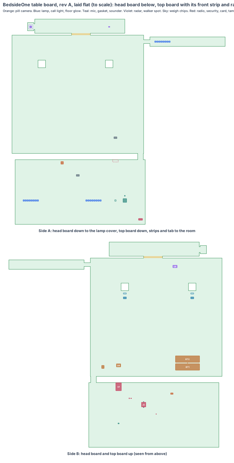
The board is code (hardware/pcb/bedsideone-board.mjs). It writes the KiCad board file (hardware/pcb/bedsideone-board.kicad_pcb), the parts list (bedsideone-board-parts.csv) and this drawing, and checks every part:
- every part sits on its board with a 0.3 mm edge margin and no two parts overlap on the same side; no part sits in the notches round the load-cell blocks, and nothing under the load-cell bars reaches them;
- every part’s height fits its gap: 7.6 mm under the head board, 31.9 mm above it, 3.5 mm under the top board, 51.9 mm above it, 2.5 mm in front of the front strip;
- the camera chip sits on the Ø10 window, the lamp LEDs over the thinned opal, the sounder over the tone holes, the mic and its gasket on the mic port, the tamper switch on the cover boss, the walker-spot chip at its window and the floor-glow LEDs behind the kick-board slot (within 1 mm, from cad/bedsideone-cad.mjs);
- the radar chip, on the folded tab, is centred on the radar window in 3D, every tab corner stays behind the front skin, and all five radar calls in the CAD are inside the chip’s view (worst: legs over the bed edge at 54.5° across, against ±70°);
- the walker seat at its parking spot is inside the distance chip’s 27° cone, and all four pill-box corners inside the camera’s 66 × 52° view, straight down;
- the folds and flexes stay inside the table: the front strip below the cavity ceiling, the up flex inside the 20 × 20 cable way, the glow strip below the bottom shelf and inside the side panels;
- the radio module’s antenna end is at the head board’s front edge with a keep-out under it, and the radio is 161 mm from the camera chip.
KiCad design rule check: 0 violations (KiCad 10, 4 Nov 2026). Each part is drawn at its real size, as a placeholder outline until its full footprint is added. Numbers marked est. are estimates.
1. The shape: five pieces on one board
| Value | |
|---|---|
| Head board | 415 × 206 mm, 1.6 mm, rigid, 4 layers; x −200 to 215, y 44 to 250; side A 8 mm above the lamp cover (962 mm above the floor) |
| Top board | 420 × 376.8 mm, 1.6 mm, rigid, 4 layers; side A 4 mm above the cavity floor (540 mm); two 24 × 24 notches round the load-cell blocks |
| Front strip | 287.4 × 45 mm, 0.8 mm, rigid, 2 layers, on a 60 × 6 mm flex bent 90° up (radius 3.8 mm); side A 3 mm behind the front face |
| Radar tab | 20 × 26 mm, 0.8 mm, rigid, 2 layers, on a 3 mm flex at the front strip’s left end, folded 15° towards the bed |
| Up flex | 18 mm wide, about 463 mm (est.): top board back edge, through the 20 × 20 cable way, up the upstand, into the head |
| Glow tail and strip | 12 mm wide, about 523 mm (est.), down the right side panel; then a 240 × 30 mm, 2-layer strip standing 3 mm behind the kick board |
Why this shape: the camera has to be high over the pill box, the weigh chips next to the load cells, the radar and walker chips at the front face, and the floor glow at the floor. One board with two long flexes reaches all four places without a second board or a cable between boards.
Changes the table CAD needs (rev T, the next BedsideOne board step):
- a Ø3 mic port with a membrane in the lamp cover at x 120, y 120 (the bench mic was on the XIAO in the head);
- a 1.5 mm boss on the lamp cover under the tamper switch;
- a 14 × 3 mm slot in the top box’s floor and in both shelves at the right front corner for the glow tail, and clips on the side panel to hold it;
- a Ø8 grommet in the top box’s back for the 5 V lead;
- the bench camera was tilted 10°; the camera chip now looks straight down, which the CAD’s view check is updated to (all four corners already fit, see section 2).
2. What is on the board
The S1 sensor core (radio module, power block, security chip and software), in BedsideOne’s shape.
| Ref | Part | Size (mm) | Where |
|---|---|---|---|
| U1 | Espressif ESP32-S3-WROOM-1-N16R8: ESP32-S3, 16 MB flash, 8 MB PSRAM for camera frames, PCB antenna; FCC and CE certified; antenna at the head board’s front edge | 18 × 25.5 × 3.1 | head, top |
| U2, U9 | Microchip ATECC608B security chip (signs every call); ID chip | 2 × 3 | head, top |
| J2 | hinged, latched microSD socket: our software starts from the card | 14 × 15 × 1.9 | head, top |
| MK1 | Infineon IM69D130 MEMS mic, bottom port over a Ø1 hole in the board | 4 × 3 × 1.2 | head, top |
| U11 | camera rails and the 24 MHz MEMS oscillator | 8 × 5 zone | head, top |
| U7 | level shifter for the LED data lines | 2 × 2 | head, top |
| U10 | OmniVision OV2640 2 MP camera chip under an M7 lens holder, 66 × 52° lens, straight down through the Ø10 window | 8.5 × 8.5 × 7.5 (est.) | head, cover side |
| D1–D16 | 16 RGB LEDs with built-in drivers (5050, WS2812B class) over the thinned opal: reading lamp and call light | 5 × 5 × 1.6 | head, cover side |
| LS1, Q1 | 12 × 12 mm SMD sounder over the tone holes, and its driver | 12 × 12 × 3 (est.) | head, cover side |
| GK1 | silicone sound gasket from the board hole to the mic port | Ø5 × 8 (est.) | head, cover side |
| SW1 | Omron D2F-01 tamper switch, pressed by the lamp cover | 12.8 × 5.8 × 6.5 | head, cover side |
| TP1 | factory pads: USB, serial, boot, enable, rails | 10 × 6 | head, cover side |
| J1 | Molex Micro-Fit 3.0 2-way vertical header, latched: 5 V from the listed adapter’s lead (exact part number to confirm) | 8 × 10 × 9.5 (est.) | top, up |
| U4 | 5 V input protection, TI BQ24074 charger with power path and NTC input, TI TPS63020 3.3 V buck-boost | 14 × 10 zone | top, up |
| BT1, BT2 | two Keystone 1042-class SMT holders for Samsung INR18650-35E cells | 77 × 21 × 21 (est.) | top, up |
| RT1 | 10 k NTC thermistor between the cells, read by the charger | 0603 | top, up |
| U5, U6 | Nuvoton NAU7802 24-bit weigh chips, one per load cell, with four gauge-wire pads each (PD1, PD2) by the cells’ fixed ends | 10 × 6.2 × 1.75 (est.) | top, up |
| U8 | radar power (TI LP87745-class), 40 MHz crystal and 2 MB flash for the radar’s own program | 14 × 8 zone | top, up |
| U12 | ST VL53L1X distance chip at the walker window (27° cone) | 4.9 × 2.5 × 1.56 | front strip, room side |
| U3 | TI IWRL6432AOP 60 GHz radar, antennas in the package, with a 14 × 14 mm keep-out, behind the radar window | 6.5 × 6.5 × 1.3 (est.) | radar tab, room side |
| D17–D24 | 8 RGB LEDs, amber at night, behind the kick board’s opal slot: the floor glow | 5 × 5 × 1.6 | glow strip, room side |
What is different for a bedside table:
- A camera chip in place of a camera board. The XIAO Sense’s camera was on a ribbon; the OV2640 now sits on the head board under its own lens holder. It sees the pill box straight down, so the bench’s 10° tilt is not needed.
- A wide-view radar chip, turned to the bed. The LD2450 module saw ±60°. The IWRL6432AOP sees about ±70° across (TI) and sits on a small tab folded 15° to the bed, as the bench radar was turned, so the bed edge, the bed and the bedroom door are all in view.
- Weigh chips next to the load cells. The gauge wires solder to pads beside each cell’s fixed end, so the tiny strain signal runs a few centimetres, not up a lead.
- A floor glow on its own strip. It lights the floor from the kick board before the parent stands, on a flex tail from the top board.
- Backup cells on the board. The PowerBoost board and loose cells become a charger chip and two soldered holders with a thermistor: the oxygen concentrator stops in a power cut, so the table keeps its dim lamp on and tells the family.
3. Every connection, checked
Our rule: every pair of parts that join is checked against both makers’ drawings and a search for known problems. No “same as KitchenOne” claims.
| Joint | Type | Keyed | Locked | Check |
|---|---|---|---|---|
| Adapter lead ↔ board | Molex Micro-Fit 3.0 2-way receptacle on the adapter’s lead, header J1 | the housing’s polarising ribs | positive latch | To check: the header part number, footprint and pin order from Molex’s drawing; a listed 5 V adapter whose lead can be ordered with this plug, and its current against the 2.4 A target |
| Load cells ↔ board | the cells’ four gauge wires soldered to PD1 and PD2, held in a strain-relief slot | wire colours to pad marks | soldered, strain relief | To check: the Adafruit 4540 cell’s wire colours and gauge against the pads; that the wires reach from the cell’s fixed end with slack (est. 20 mm) |
| Radio module ↔ board | castellated edge pads, reflow soldered | outline and pin 1 mark | soldered | Espressif’s footprint and antenna keep-out from the WROOM-1 datasheet and hardware design guide |
| Camera chip ↔ board | chip-scale package, reflow soldered; lens holder screwed and glued over it | pin 1 mark; holder pins | glued after focus | To check: the OV2640 CSP land pattern and the M7 holder outline from the maker’s drawings; the lens focus at 350 mm |
| Radar chip ↔ board | FCCSP, reflow soldered on the tab | pin 1 mark | soldered | To check: TI’s IWRL6432AOP land pattern and keep-out from its reference design; the tab’s 2-layer stack under the chip against TI’s guidance |
| Head, front strip, tab, glow strip ↔ top board | flexes, part of the board | built in | built in | no connector. Static bend radii (3.8 mm front fold; the long flexes’ folds) against the chosen maker’s minimum (to confirm) |
| Cells ↔ board | Keystone SMT holders, reflow soldered; cells held by the holders’ springs and a strap | polarity marks | strap | To check: the holder’s outline and pad drawing |
No adapters, no plug-in modules and no ribbons inside.
4. Heat
- The board draws about 0.9 W watching (est., section 5). The bedroom is the only heat source: counted at 32 °C on a summer night (est.).
- The ESP32-S3 at 0.5 W reaches about 45 °C (est.), far inside its 85 °C rating.
- The cells sit in the hollow top, away from the lamp head; charging holds outside 0–45 °C (RT1 on the BQ24074).
- The camera chip is 161 mm from the radio module, so a warm radio adds no noise to the dim night shots.
5. Power budget (est.)
| Value | |
|---|---|
| Supply | 5 V from a listed USB adapter at the wall, down the latched lead (no mains inside the table) |
| Watching (Wi-Fi, radar tracking, weigh chips, distance chip, mic) | 0.9 W |
| Camera awake for a dose | 1 W more, a few seconds per dose |
| Reading lamp | up to 2 W |
| Charging the cells | 3.6 W more, until full |
| Power cut (radar in low-power tracking, Wi-Fi only for alerts, dim battery lamp) | 0.55 W from two cells: about 27 h, aged to 80 % |
6. Factory test (every board, every time)
- Current-limited first power-on (100 mA). A short trips in about 1 s, before anything heats.
- Every rail within ±3 %; reverse 5 V does no harm. Charger: charge current, the thermistor’s hold at a hot and a cold resistor, power-path switch-over with 5 V removed.
- Our small loader flashed over the USB pads; our microSD card in, then boot: the loader starts our program from the card.
- Camera: a printed pill-box target at 350 mm, focus and every colour. Radar: a moving plate at 1 m and 3 m, straight ahead and at 50° to the side. Distance chip: a plate at 300 mm. Weigh chips: a 100 g and a 500 g weight on test cells. Mic: a test tone and a concentrator alarm pattern. Each LED colour read by a light sensor; the sounder’s level.
- The tamper switch opened and closed. Each flex bent to its fold and back once, then every chip checked again.
- Wi-Fi to the fixture. The unit’s own key goes into the security chip, the ID chip is written and the label is printed. Every result is stored against the serial number.
For each rev A batch: radio pre-scan (FCC Part 15, UK and EU radio rules, and the 60 GHz radar rule) and a 24-hour soak at 40 °C.
7. Who makes what
| Work | Who |
|---|---|
| Board shape, parts, placement, checks, KiCad files, schematics | IEMI Labs |
| The S1 core circuit (radio module, security chip, power block) | copied from KitchenOne’s board |
| The board (two 4-layer boards, three 2-layer pieces, two long flexes) | a maker that builds rigid-flex boards with long flex tails (see the makers list on the boards page) |
| Assembly, including the camera lens holder and focus, and the cell holders | the same maker or a Shenzhen assembly house |
| Software: the bedside program, the pill compartment model, the radar bed-edge tracker, the concentrator sounds | IEMI Labs, on the bench table and the makers’ evaluation boards while the board is made |
8. Cost per table, electronics (est.)
| qty 10 (rev A) | qty 1,000 | qty 10,000 | |
|---|---|---|---|
| Chips and parts (incl. the radar, camera and weigh chips and cell holders; cells and load cells extra) | $70–90 | $40–50 | $32–40 |
| Board (rigid-flex: two large rigid boards and two long flexes) | $60–90 | $14–20 | $10–14 |
| Assembly | $15–25 | $3–5 | $2–3 |
| Per table | $145–205 | $57–75 | $44–57 |
The board itself is the largest cost: two large rigid pieces and two half-metre flexes use a lot of panel. A rev B option is a smaller head board (the parts fill under a third of it) once the lamp cover’s windows can move closer together.
9. Timeline
| When | Step |
|---|---|
| Nov–Dec 2026 | the radar, camera and weigh chips on their makers’ evaluation boards beside the bench table; the radar’s view at the bed edge measured |
| Jan 2027 | BedsideOne schematics from the S1 core; placement (this drawing) into KiCad; review; rev T table CAD |
| Mar 2027 | rev A made: 10 boards plus spares; bring-up on our fixture |
| Apr 2027 | rev B (fixes), factory test software, radio pre-scan |
| May–Jun 2027 | pilot homes; certification starts |
10. Still to check
- The IWRL6432AOP package outline and land pattern, and its view at the edges, from TI’s datasheet plots and evaluation board (here 6.5 × 6.5 × 1.3 and ±70°, est.).
- The OV2640 chip-scale package, the M7 lens holder outline and a 66 × 52° lens (here 8.5 × 8.5 × 7.5, est.).
- The Micro-Fit 3.0 header part number, and a listed 5 V adapter with that plug on its lead.
- The Keystone 18650 SMT holder’s outline and pads (here 77 × 21 × 21, est.).
- The flex maker’s limits for the two long tails and their static bends.
- The rev T table CAD: the board in the table, every part checked in 3D, and the five CAD changes in section 1.
Sources
- Espressif ESP32-S3-WROOM-1 datasheet (18 × 25.5 × 3.1)
- TI IWRL6432AOP datasheet (antenna radiation patterns)
- TI E2E: IWRL6432AOP field of view (±70° azimuth quoted)
- TI IWRL6432AOP reference design
- OmniVision OV2640 (UXGA 1600 × 1200, 15 fps)
- ST VL53L1X time-of-flight sensor
- Nuvoton NAU7802 24-bit ADC for load cells
- Infineon IM69D130 MEMS microphone
- TI BQ24074 charger with power path
- TI TPS63020 buck-boost converter
- Keystone 18650 cell holders
- Samsung INR18650-35E specification
- Molex Micro-Fit 3.0 connectors
- Microchip ATECC608B
- Omron D2F datasheet
- The table, its sizes and its calls: BedsideOne’s design
- The board platform: our own boards
Design review (4 Nov 2026)
Every board is checked by the same rules (products/_shared/board-rules.mjs), one for each lesson any of our boards has taught us. BedsideOne’s board was made with every rule from the start, so nothing had to be fixed: 16 pass, 2 fixed, 7 to prove, 0 fail. The full review, with every number and its source, is on the board page. It shows:
- Pill camera pixels: one 6 mm tablet left in the farthest compartment fills about 21 px against an 8 px need; the camera chip’s data rate and its own image processor have wide spare.
- Radar view: all five radar calls are inside the chip’s view, the closest (legs over the bed edge) 15.5° from its edge; to prove on TI’s evaluation board beside a real bed, because TI gives the view as plots, not a table.
- Power cut: two cells give about 27 h with the dim lamp on, aged to 80 % (to prove on rev A; target 24 h), because a parent on home oxygen needs the lamp and the family told when the concentrator stops.
- The latched microSD (J2) is fitted, and our software starts from it; updates never run between the evening dose and the morning.
- Conformal coating against a spilt glass of water is asked for in the quote.
- The tamper switch against the lamp cover’s boss, and the two long flexes routed and held in the table, are checked in the rev T CAD and on rev A.
- Fast lines on a solid ground plane (to prove, lesson: planes, from the CricketOne test-board layout of 4 Nov 2026): 1 camera MIPI link (100 Ω pairs); USB (90 Ω); antenna feed (50 Ω, keep-out on every layer); card lines (length-matched, no vias under the socket). Ground on the layer next to the parts (inner layer 1, supply on inner layer 2; the whole bottom of a 2-layer section), one via beside each ground and supply pad and none in pads, no copper or vias in the antenna keep-out on any layer or under the card socket, the impedance lines routed first with a test coupon. The quote asks for it; the routed board’s design rule check proves it.
The request for quote is /build/bedsideone-quote.