DampOne: one circuit board of our own
What changed (3 Nov 2026). The rev A bench fan is built from bought boards joined by leads: a XIAO ESP32-S3, two Adafruit MLX90640 heat-camera boards, an SHT45 board, an LD2410C radar module, a MAX9814 mic board, two NeoPixel sticks and an ATECC608 board. DampOne now gets one circuit board of our own, like CricketOne and RoomOne, with every chip placed straight onto it. An assembly house makes and tests it.
- The chips: the ESP32-S3 certified radio module (soldered by its edge pads), two bare Melexis heat-camera chips, an Infineon 60 GHz radar chip with its antennas built in, the Sensirion humidity chip, a MEMS mic, sixteen call-light LEDs, a sounder, the fan drive, the security chip and the tamper switch.
- The shape: the grille’s sealed rim is a square ring around the air path, so the board is one rigid 194 × 194 mm square ring with a 118 mm opening, lying flat in the rim. Side A faces the room: everything that sees, lights or sounds through the grille’s underside. Side B faces the ceiling: the radio, the lead from the housing, the tamper switch and the humidity chip.
- One bend. The wall heat camera must look sideways and 30° down at the outside wall. It sits on a small tab joined to the ring by a 4 mm flex; when fitted, the flex bends the tab 60° up so the camera looks out of the side window exactly along the CAD’s wall view.
- A humidity tongue. A U-shaped slot cuts a small tongue at the side vents, so the humidity chip reads the room air, not the board.
- Mains stays above the ceiling. The Mean Well 5 V supply and the fan motor stay in the housing; only 5 V and the fan’s two signal wires come down one latched lead.
- The rev A bench fan stays as it is. It proves the calls and the software, which move to this board unchanged (same ESP32-S3 family).
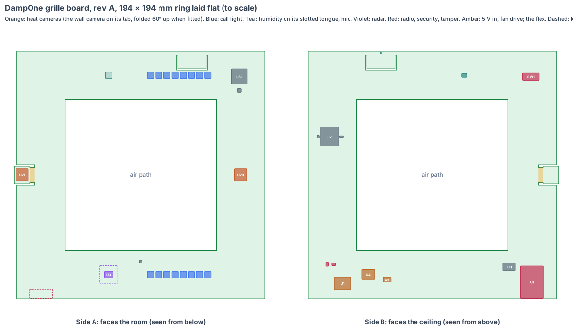
The board is code (hardware/pcb/dampone-board.mjs). It writes the KiCad board file (hardware/pcb/dampone-board.kicad_pcb), the parts list (dampone-board-parts.csv) and this drawing, and checks every part:
- every part sits on the ring or the tab with a 0.3 mm edge margin, clear of the air-path opening, the camera notch and the tongue slot, and no two parts overlap on the same side;
- the ring stays 1 mm inside the rim walls and 2 mm from the air-path walls, and every part’s height fits its side: 7.5 mm on the room side, 15.9 mm on the ceiling side;
- the floor camera, radar chip, sounder, mic and its gasket, tamper switch and both rows of call-light LEDs each sit on their own window in the grille CAD (within 1 mm);
- the humidity chip is on its tongue at the side vents, at least 30 mm from every part that is warm all the time (170 mm in this layout);
- the radio module’s antenna end is at the ring’s outer edge, with the keep-out under it;
- folded, the wall camera looks 30° below level, its axis meets the side wall 0.2 mm from the window centre, and its can stays 0.5 mm clear of the wall.
KiCad design rule check: 0 violations, 0 unconnected items (KiCad 10, 3 Nov 2026). Each part is drawn at its real size, as a placeholder outline until its full footprint is added.
Sizes come from the grille CAD (cad/dampone-cad.mjs, rev A: fascia 200 × 200 × 30 mm, rim cavity 196 × 196 × 26 inside, air-path walls 114 × 114) and the chip datasheets. Numbers marked est. are estimates.
1. The shape: one square ring in the grille rim
| Value | |
|---|---|
| Ring | 194 × 194 mm outside, 118 × 118 opening, 1.6 mm, rigid, 4 layers (ground and power inside) |
| Where | flat in the rim, side A 8.0 mm above the rim floor (20 mm below the ceiling), side B 16.4 mm below the rim top |
| Wall-camera tab | 12 × 14 mm, 2 layers, 0.8 mm, on a 4 × 12 mm two-layer flex from a notch in the ring’s wall side; bent 60° up when fitted |
| Humidity tongue | x 29–51, y 83–97 (the back side, at the vents), cut round by a 1 mm U-shaped slot |
Why this shape: the rim is the only place in the fan that is out of the air path and sealed from steam, and it runs all the way round. One ring reaches every window on the underside, the side window and the vents without a second board; only the side-looking camera needs a bend.
Three changes to the grille CAD (made in rev T, 3 Nov 2026; nothing is bought for them):
- The wall camera window moves 2 mm down, from 15 to 17 mm below the ceiling, to sit on the folded camera’s axis.
- A Ø6 grommet in the fascia top (at x 70, y −85, over J1) for the 4-core lead from the housing (the rev A CAD has the cavity sealed with no lead path).
- The radar skin’s thickness is set for 60 GHz (about 1.5 mm ASA over the radar in place of 2 mm, est., half a wavelength in the plastic; to be measured): a 16 × 16 × 0.5 mm pocket inside the rim floor over the radar keep-out.
2. What is on the board
The S1 sensor core (radio module, radar chip, humidity chip, power block, security chip and software), in DampOne’s shape. Only what is different for a bathroom fan is described after the table.
| Ref | Part | Size (mm) | Side |
|---|---|---|---|
| U1 | Espressif ESP32-S3-WROOM-1-N8R8: ESP32-S3, 8 MB flash, 8 MB PSRAM, PCB antenna; FCC and CE certified; soldered by its edge pads, antenna at the ring’s outer edge | 18 × 25.5 × 3.1 | ceiling |
| U2 | Microchip ATECC608B security chip (signs every call) | 2 × 3 | ceiling |
| U9 | ID chip: product, board version, serial, calibration | 2 × 3 | ceiling |
| J1 | Molex Micro-Fit 3.0 single-row vertical header, 4 circuits, latched: 5 V, ground, fan PWM, fan tach (exact part number to confirm) | 13 × 10 × 9.5 (est.) | ceiling |
| U4 | 5 V input: polyfuse, surge suppressor, reverse block, TI TPS62A02 3.3 V buck | 10 × 8 zone | ceiling |
| U5 | fan drive: 25 kHz PWM output and tach input | 6 × 4 zone | ceiling |
| U10 | Sensirion SHT45 humidity and temperature chip, on the tongue at the vents | 1.5 × 1.5 | ceiling |
| MK1 | Infineon IM69D130 MEMS mic, bottom port over a Ø1 hole in the board | 4 × 3 × 1.2 | ceiling |
| SW1 | Omron D2F-01 tamper switch, under the Ø4 plunger hole in the top | 12.8 × 5.8 × 6.5 | ceiling |
| TP1 | factory pads: USB, serial, boot, enable, power rails | 10 × 6 | ceiling |
| U20 | Melexis MLX90640ESF-BAA heat-camera chip (32 × 24, 110 × 75° lens), TO39 can, looking straight down through the floor window | Ø9.4 × 6.6 (est.) | room |
| U21 | the same chip on the folded tab, looking at the outside wall through the side window | Ø9.4 × 6.6 (est.) | room (tab) |
| U3 | Infineon BGT60TR13C 60 GHz radar chip, antennas in the package, with a 14 × 14 mm keep-out | 6.5 × 5.0 × 0.9 | room |
| GK1 | silicone sound gasket from the board hole to the mic port | Ø5 × 8 (est.) | room |
| D1–D16 | 16 × RGB LEDs with built-in drivers (5050, WS2812B class), 8 behind each opal slot | 5 × 5 × 1.6 | room |
| LS1, Q1 | 12 × 12 mm SMD sounder under the tone holes, and its driver | 12 × 12 × 3 (est.) | room |
| U7 | level shifter for the LED data line | 2 × 2 | room |
| ANT | keep-out under the radio module’s antenna | 18 × 7 | room |
What is different for a bathroom fan:
- Bare heat-camera chips. The two Adafruit boards were the costliest parts. The bare MLX90640 chip is the same sensor without the breakout, soldered through the board. Both share one I2C bus: the factory writes the second chip’s address (the MLX90640 address is stored in its own memory) before the board is fitted.
- Radar on the board. The LD2410C was a module on pins. The BGT60TR13C has its antennas inside its package, so it solders straight on the ring and sees through the grille’s underside. It is still a radar: no camera picture and no voice recording in a bathroom.
- A mic chip in place of a mic board. The MEMS mic sends digital sound straight to the ESP32-S3; the running-water and washer models listen for sound levels and patterns, and keep no recording.
- The fan stays above the ceiling. The board drives the fan’s own PWM input and reads its speed through one latched lead. Mains never comes below the ceiling.
Sale boards run from the ESP32-S3’s own flash, update over Wi-Fi with two system copies (a bad update rolls back by itself), and never update while the room is in use.
3. Every connection, checked
Our rule: every pair of parts that join is checked against both makers’ drawings and a search for known problems. No “same as RoomOne” claims.
| Joint | Type | Keyed | Locked | Check |
|---|---|---|---|---|
| Housing lead ↔ board | Molex Micro-Fit 3.0 4-way receptacle on the lead, header on side B | the housing’s polarising ribs | positive latch | the only cable. To check: the exact header part number, its footprint and the 5 V / ground / PWM / tach pin order from Molex’s drawing; the receptacle’s crimp terminal against the lead’s wire size. Mains stays in the housing |
| Lead ↔ supply and fan (housing) | the same lead’s other end, at the IRM-10-5 output and the fan’s own connector | to check | to check | to check: the fan body’s motor connector is the fan maker’s; we make no claim until we have its drawing (no “same as” connectors) |
| Radio module ↔ board | castellated edge pads, reflow soldered | outline and pin 1 mark | soldered | Espressif’s footprint and antenna keep-out from the WROOM-1 datasheet and hardware design guide |
| Heat-camera chips ↔ board | TO39 leads through the board, soldered | the can’s tab | soldered | Melexis land pattern and lead pitch from the MLX90640 datasheet; the tab’s two layers carry I2C and power over the flex |
| Wall-camera tab ↔ ring | a 2-layer flex, part of the board | built in | built in | no connector. Bend radius 3.8 mm (60° over 4 mm) against the maker’s minimum for a static bend (to confirm, about 10 × the flex thickness) |
| Radar, humidity, mic, security chips ↔ board | soldered on the board | pin 1 marks | soldered | each maker’s land pattern; the mic’s port hole and gasket from Infineon’s IM69D130 guidance |
| Keys: none. Tamper switch, sounder | soldered on the board | the parts’ own pins | soldered | Omron D2F drawing |
No adapters, no plug-in modules and no ribbons inside.
4. Heat
- The board draws about 0.6–0.8 W (est., section 5); the fan motor’s 1.5–4 W is above the ceiling, in the air stream.
- The problem is not cooling, it is reading. The humidity chip must read the room’s air, not the board. It sits on its own slotted tongue at the side vents, about 170 mm from the radio module and the power block, and 14 mm from the nearest call-light LED, which only lights during a call; the program flags humidity readings taken while the light is on.
- The heat cameras read the wall and floor, not the board: their cans look out through their windows and the ring’s copper keeps the board at one even temperature, which the cameras’ own built-in reference handles.
- Rev A logs the board’s own temperature next to the humidity reading; the bench test compares the SHT45 with a reference hygrometer after a shower, with the radio busy.
5. Power budget (est.)
| Value | |
|---|---|
| Supply | 5 V from the Mean Well IRM-10-5 in the housing (10 W), down the latched lead |
| Watching (Wi-Fi, radar, two heat cameras at 1 Hz, humidity, mic) | 0.6 W |
| A call (8 LEDs lit and the tone) | 0.8 W peak |
| Fan on boost (motor, above the ceiling) | about 4 W more |
That is about 5 W at boost, half the supply’s rating. The radar chip in place of the LD2410C saves about 0.3 W (est.). The first rev A fans in a real bathroom replace these estimates.
6. Factory test (every board, every time)
- Current-limited first power-on (100 mA). A short trips in about 1 s, before anything heats.
- Every rail within ±3 %; reverse 5 V does no harm.
- Our small loader flashed over the USB pads; our microSD card in, then boot: the loader starts our program from the card (the card socket added by the design review, 4 Nov 2026). The second heat-camera chip’s address written.
- Heat cameras: a warm and a cold plate in front of each window position; every pixel answers. Radar: a moving plate at 1 m and 2 m. Humidity: a reading in the fixture’s dry and damp chambers (est.). Mic: a test tone. Each LED colour read by a light sensor; the sounder’s level.
- Fan drive: PWM out and tach in, on a test fan. The tamper switch opened and closed. The flex bent to 60° and back once, then the wall camera checked again.
- Wi-Fi to the fixture. The unit’s own key goes into the security chip, the ID chip is written and the label is printed. Every result is stored against the serial number.
For each rev A batch: radio pre-scan (FCC Part 15, UK and EU radio rules, and the 60 GHz radar rule), 24-hour soak in a damp chamber, and the fan’s own electrical safety pre-checks.
7. Who makes what
| Work | Who |
|---|---|
| Board shape, parts, placement, checks, KiCad files, schematics | IEMI Labs |
| The S1 core circuit (radio module, radar, humidity and security chips, power block) | copied from RoomOne’s board |
| The board (4-layer ring with a 2-layer flex and tab) | a maker that builds rigid-flex boards (see the makers list on the boards page) |
| Assembly, including the through-board heat-camera cans | the same maker or a Shenzhen assembly house |
| Software: the damp program, the radar presence code, the water and washer models on the new mic and bare heat-camera chips | IEMI Labs, on the bench fan and the makers’ evaluation boards while the board is made |
8. Cost per fan, electronics (est.)
| qty 10 (rev A) | qty 1,000 | qty 10,000 | |
|---|---|---|---|
| Chips and parts (incl. two heat-camera chips and the radar chip) | $120–150 | $85–100 | $70–85 |
| Board (194 mm ring with a flex tab, 4 layers) | $25–40 | $5–8 | $3.5–5 |
| Assembly | $15–25 | $3–5 | $2–3 |
| Per fan | $160–215 | $93–113 | $76–93 |
The two heat-camera chips are most of the cost (about $60–70 together at volume, est.). The bench parts for the same jobs cost about $205 at qty 1 (bom.csv, without the fan body and supply). A cheaper 32 × 24 or 16 × 12 heat-camera chip for the floor view is a rev B option once the water-call tests show how many pixels the floor needs.
9. Timeline
| When | Step |
|---|---|
| Nov–Dec 2026 | the radar, mic and bare heat-camera chips on their makers’ evaluation boards beside the bench fan; the water and washer models re-checked on their data |
| Jan 2027 | DampOne schematics from the S1 core; placement (this drawing) into KiCad; review |
| Feb 2027 | rev A made: 10 boards plus spares; bring-up on our fixture |
| Mar 2027 | rev B (fixes), factory test software, radio pre-scan |
| Apr–May 2027 | pilot bathrooms in damp homes; certification starts |
10. Still to check
- The bare MLX90640ESF-BAA can’s exact outline, lead pitch and land pattern from the Melexis datasheet (here Ø9.4 × 6.6, est.).
- The Micro-Fit 3.0 header part number, footprint and pin order, and the fan body’s own motor connector.
- The flex’s minimum static bend radius from the chosen maker against the 3.8 mm used here.
- The 60 GHz radar rule for a ceiling device in each market (FCC Part 15.255, UK and EU short-range device rules), and presence in the bath through the 1.5 mm rev T skin.
- The radio module’s range from inside the grille rim, under plasterboard, to a home router.
- The humidity reading error with the call light and radio busy, against a reference hygrometer.
- The CAD alignment and quote pack (the board in the grille CAD, the product page’s board section, QUOTE.md and its page), as done for CricketOne rev T.
Sources
- Espressif ESP32-S3-WROOM-1 datasheet (18 × 25.5 × 3.1)
- Melexis MLX90640, 32 × 24 thermal sensor (BAA: 110 × 75° view; the BAB is 55 × 35°)
- Infineon BGT60TR13C, 60 GHz radar, antennas in package, 6.5 × 5.0 × 0.9
- Infineon IM69D130 MEMS microphone
- Sensirion SHT45
- TI TPS62A02 buck converter
- Molex Micro-Fit 3.0 connectors
- Microchip ATECC608B
- Omron D2F datasheet
- Mean Well IRM-10 datasheet
- The fan, its sizes and its calls: DampOne’s design
- The board platform: our own boards
- The camera short that started our board rule: the first stump, section 9
Design review (4 Nov 2026)
Every board is checked by the same rules (products/_shared/board-rules.mjs), one for each lesson any of our boards has taught us. The full review, with every number and its source, is on the board page. It changed this board:
- Added J2, a hinged, latched microSD socket (ceiling side at x 80, y 30): the maker flashes our small loader into the ESP32-S3, and it starts our program from the card.
- Heat cameras corrected to the MLX90640ESF-BAA (110 × 75°). The board named the BAB, which has the narrow 55 × 35° lens.
- Where the fan goes: at 2.5 m the wall heat camera puts only 2.0 px on a 0.3 m cold band at the top corner, so the install guide places the grille within 2 m of the outside wall (2.5 px), as extract fans usually are.
- Conformal coating (steam and condensation) asked for in the quote.
- In the grille CAD (rev T, 3 Nov 2026): the ring and its folded wall-camera tab are placed in the grille (cad/dampone-t-cad.mjs) and every part is checked in 3D against the fascia with a 0.3 mm skin inside every wall (windows, vents and the air-path walls included) and against the 5 V supply that stays in the housing. Nothing touches: the floor heat camera’s lens is 0.40 mm above the rim floor, the tallest ceiling-side part 4.69 mm below the rim top, and the folded wall camera 0.48 mm from the side wall, on the axis of the window that moved 2 mm down. The mic gasket seals on the rim floor round the mic port. Every bought bench part in the grille is out; the board does every job.
- Fast lines on a solid ground plane (to prove, lesson: planes, from the CricketOne test-board layout of 4 Nov 2026): USB (90 Ω); antenna feed (50 Ω, keep-out on every layer); card lines (length-matched, no vias under the socket). Ground on the layer next to the parts (inner layer 1, supply on inner layer 2; the whole bottom of a 2-layer section), one via beside each ground and supply pad and none in pads, no copper or vias in the antenna keep-out on any layer or under the card socket, the impedance lines routed first with a test coupon. The quote asks for it; the routed board’s design rule check proves it.
The request for quote is /build/dampone-quote.