RoomOne: one circuit board of our own
What changed (3 Nov 2026). The rev A bench thermostat is built from bought boards joined by leads: a XIAO ESP32-S3, a SEN66 air module on a cable, an LD2410C radar module, an e-paper board, an ATECC608 breakout, a Pololu regulator and NeoPixel stick, all on a carrier board. RoomOne now gets one circuit board of our own, like CricketOne and CellOne, with every chip placed straight onto it. An assembly house makes and tests it.
- The chips: the ESP32-S3 certified radio module (soldered by its edge pads), an Infineon 60 GHz radar chip with its antennas built in, a Bosch particle sensor with no fan, Sensirion CO2, gas and humidity chips, the e-paper drive, two key switches, eight call-light LEDs, a sounder, three relays, the 24 VAC supply, the security chip and the tamper switch.
- The shape: the thermostat is flat, so this board is one rigid 128 × 98 mm plate that fills the body. Side A faces the room: everything that sees, lights, sounds or is pressed through the front face. Side B faces the wall: the radio, relays, supply and the wires in.
- An air corner. A 1 mm slot cut in an L shape keeps the temperature, humidity, gas and particle chips away from the board’s own heat.
- The rev A bench thermostat stays as it is. It proves the calls and the software, which move to this board unchanged (same ESP32-S3 family).
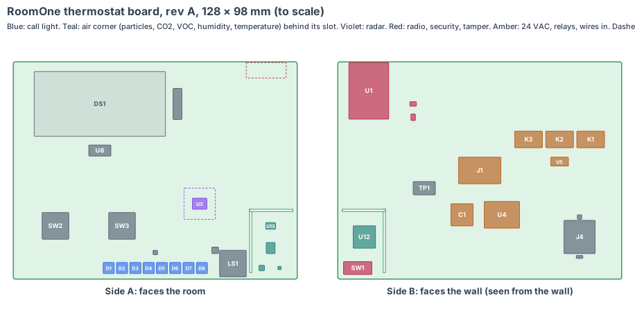
The board is code (hardware/pcb/roomone-board.mjs). It writes the KiCad board file (hardware/pcb/roomone-board.kicad_pcb), the parts list (roomone-board-parts.csv) and this drawing, and checks every part:
- every part sits on the board with a 0.3 mm edge margin, clear of the air-corner slot, and no two parts overlap on the same side;
- every part’s height fits its side: 6.5 mm on the room side, 16.4 mm on the wall side;
- the key switches, radar chip, sounder, particle sensor, e-paper panel and call-light LEDs each sit on their own window in the thermostat CAD (within 1 mm);
- the air chips are inside the slotted corner, and the temperature chip is at least 30 mm from every warm part (47 mm in this layout);
- the radio module’s antenna end is at the board’s top edge, at least 10 mm from the e-paper panel;
- the wire terminal sits inside the wall plate’s 40 × 30 mm wire opening.
KiCad design rule check: 0 violations, 0 unconnected items (KiCad 10, 3 Nov 2026). Each part is drawn at its real size, as a placeholder outline until its full footprint is added.
Sizes come from the thermostat CAD (cad/roomone-cad.mjs, rev A: 140 × 110 × 32 mm, 135 × 105 inside, front face 25.5 mm in front of the wall plate) and the chip datasheets. Numbers marked est. are estimates.
1. The shape: one flat board, filling the thermostat
| Value | |
|---|---|
| Board | 128 × 98 × 1.6 mm, rigid, 4 layers (ground and power inside) |
| Where | parallel to the wall, side A 7.0 mm behind the inside of the front face, side B 16.9 mm in front of the wall plate |
| Margin | 3.5 mm a side inside the 135 × 105 body, for the clips |
| Air corner | x 43–64, y −49 to −18 (bottom right, seen from the room), cut off by a 1 mm L-shaped slot with two bridges for the traces |
Why this shape: a guest-room thermostat is a flat box on the wall. One flat board can reach every window from one side and every wire from the other, so it needs no flex and no second board.
Three changes to the thermostat CAD (made in rev T, 3 Nov 2026; nothing is bought for them):
- A 6 mm particle window with a clear cover in the front face at x 52, z 1,125, over the particle sensor. The SEN66’s side vents stay for the air corner.
- A rib on the wall plate (6 × 3 mm, 10.1 mm deep, at x 55, z 1,107) that presses the tamper switch on the board’s back: its face stops 0.3 mm short of the switch body, and the plunger stands above the body (operating position 7.4 ± 0.2 mm over the mounting face, Omron D2F datasheet). Taking the thermostat off the plate opens it.
- The radar window’s thickness is set for 60 GHz (about 1.5 mm PC-ABS in place of 1.0 mm, est., half a wavelength in the plastic; to be measured).
2. What is on the board
The S1 sensor core (radio module, sensors, power block, security chip and software), in RoomOne’s shape. Only what is different for a guest room is described after the table.
| Ref | Part | Size (mm) | Side |
|---|---|---|---|
| U1 | Espressif ESP32-S3-WROOM-1-N8R8: ESP32-S3, 8 MB flash, 8 MB PSRAM (a 7-day event buffer), PCB antenna; FCC and CE certified; soldered by its edge pads | 18 × 25.5 × 3.1 | wall |
| U2 | Microchip ATECC608B security chip (signs every call) | 2 × 3 | wall |
| U9 | ID chip: product, board version, serial, calibration | 2 × 3 | wall |
| K1–K3 | 3 × Omron G5V-1-DC5 relays: fan (G), cool (Y), heat (W) | 12.5 × 7.5 × 10 each | wall |
| U5 | relay drivers with flyback diodes | 8 × 4 zone | wall |
| J1 | 5-way push-in wire terminal, 3.5 mm pitch (R, C, G, Y, W) | 19 × 12 × 14 (est.) | wall |
| U4 | 24 VAC supply: fuse, 36 V surge suppressor, bridge rectifier, TI LMR36015 buck to 5 V, 3.3 V regulator | 16 × 12 zone | wall |
| C1 | 470 µF 50 V capacitor (rectified 24 VAC) | Ø10 × 10.5 (est.) | wall |
| U12 | Sensirion SCD41 CO2 sensor (reflow solderable), in the air corner | 10.1 × 10.1 × 6.5 | wall |
| SW1 | Omron D2F-01 tamper switch, pressed by the wall-plate rib | 12.8 × 5.8 × 6.5 | wall |
| TP1 | factory pads: USB, serial, boot, enable, power rails | 10 × 6 | wall |
| U3 | Infineon BGT60TR13C 60 GHz radar chip, 1 transmit and 3 receive antennas in the package, behind the radar window, with a 14 × 14 mm keep-out | 6.5 × 5.0 × 0.9 | room |
| U13 | Bosch BMV080 particle sensor (PM1, PM2.5, PM10, no fan) behind the new particle window | 4.4 × 3.0 × 3.0 | room |
| U11 | Sensirion SGP41 VOC and NOx chip, in the air corner | 2.44 × 2.44 | room |
| U10 | Sensirion SHT45 humidity and temperature chip, in the air corner | 1.5 × 1.5 | room |
| DS1, J2, U6 | 2.13 in e-paper panel on the front frame; its tail soldered to 24 pads by hot bar (no connector); the panel maker’s booster circuit | 59.2 × 29.2 × 1.0 panel | room |
| SW2, SW3 | 2 × Omron B3F-1000 key switches under printed 16 mm key caps | 12 × 12 × 4.3 | room |
| D1–D8 | 8 × RGB LEDs with built-in drivers (5050, WS2812B class) behind the opal slot | 5 × 5 × 1.6 | room |
| LS1, Q1 | 12 × 12 mm SMD sounder under the tone holes, and its driver | 12 × 12 × 3 (est.) | room |
| ANT | keep-out opposite the radio module’s antenna | 18 × 7 | room |
What is different for a guest room:
- Radar on the board. The LD2410C was a module on pins. The BGT60TR13C has its antennas inside its package, so it solders straight on a normal board and sees breathing through the front window. It is still a radar: no camera and no microphone in a sleeping room.
- Air chips on the board. The SEN66 was a module on a cable. Its jobs are split over four chips soldered on the board: particles (BMV080), CO2 (SCD41), VOC and NOx (SGP41), humidity and temperature (SHT45). The smoke-and-vape classifier was trained on SEN66 data, so it is re-checked on these chips (see “Still to check”).
- HVAC relays and 24 VAC stay as in the bench design, now on the same board, with the wire terminal behind the wall plate’s opening.
Sale boards run from the ESP32-S3’s own flash, update over Wi-Fi with two system copies (a bad update rolls back by itself), and never update during a guest’s stay at night.
3. Every connection, checked
Our rule: every pair of parts that join is checked against both makers’ drawings and a search for known problems. No “same as CricketOne” claims.
| Joint | Type | Keyed | Locked | Check |
|---|---|---|---|---|
| Room wires ↔ board | 5-way push-in terminal on side B, through the wall plate opening | the R, C, G, Y, W labels on the plate and the board | spring clamp; release by tool | the only wire joint. Wire range (18–22 AWG thermostat cable) and the terminal’s rated current against the maker’s sheet; the R and C positions match the plain thermostat so an installer wires it the same way |
| Radio module ↔ board | castellated edge pads, reflow soldered | the module’s outline and pin 1 mark | soldered | Espressif’s footprint and antenna keep-out from the WROOM-1 datasheet and hardware design guide |
| E-paper panel ↔ board | the panel’s own tail, soldered by hot bar | the tail’s one-sided pads | soldered | no connector, so it cannot be put in reversed (the fault that shorted our CricketOne test board on 3 Nov 2026). Pad pitch and order from the panel maker’s drawing |
| Particle sensor ↔ board | the BMV080’s own flex tail | its one-sided pads | soldered, or its maker’s latched connector | to check: Bosch’s integration guide decides between hot-bar soldering the tail and Bosch’s named mating connector; we make no claim until we have read it |
| Radar, CO2, gas, humidity chips ↔ board | soldered on the board | pin 1 marks | soldered | each maker’s land pattern |
| Keys, tamper switch, relays | soldered on the board | the parts’ own pins | soldered | Omron B3F, D2F and G5V-1 drawings |
No adapters, no plug-in modules and no cables inside.
4. Heat
- The whole board draws about 0.6–0.9 W (est., section 5). A plain thermostat draws about 0.3–1 W.
- The problem is not cooling, it is reading. A thermostat must read the room, not itself. The radio module, the supply and the relays are kept on the top and left of the board, the air chips in the bottom-right corner behind the slot, 47 mm from the nearest warm part.
- The body’s bottom vents feed the air corner first; warm air leaves at the top vents, past the radio module.
- Rev A logs its own board temperature beside the room temperature; the bench test compares the SHT45 with a reference thermometer in still air with the radio busy.
5. Power budget (est.)
| Value | |
|---|---|
| Supply | the room’s 24 VAC from R and C (20–30 VAC), inside a 40 VA thermostat transformer |
| Guest in, idle (Wi-Fi, radar, air chips, e-paper still) | 0.6 W |
| Heating or cooling (two relays in) | 0.9 W |
| Air event (red light flashing and the tone) | 1.1 W |
This is about half the bench thermostat’s 1.3–1.8 W, mostly from the fanless particle sensor and the radar chip in place of the SEN66 fan and the radar module. The first rev A thermostats on a real PTAC replace these estimates.
6. Factory test (every board, every time)
- Current-limited first power-on (100 mA). A short trips in about 1 s, before anything heats.
- Every rail within ±3 %; the 24 VAC input at 20 and 30 VAC; a wire on the wrong terminal does no harm (fuse and suppressor).
- Our small loader flashed over the USB pads; our microSD card in, then boot: the loader starts our program from the card (the card socket added by the design review, 4 Nov 2026).
- Radar: a moving plate at 1 m and 3 m. Air chips: a clean-air reading in the fixture and one puff of test aerosol (est.). Keys pressed by the fixture’s pins. Each LED colour read by a light sensor; the sounder’s level.
- Each relay switched with a 24 VAC load; the tamper switch opened and closed.
- Wi-Fi to the fixture. The unit’s own key goes into the security chip, the ID chip is written and the label is printed. Every result is stored against the serial number.
For each rev A batch: radio pre-scan (FCC Part 15, and the 60 GHz radar rule), 24-hour soak, and UL 60730-2-9 pre-checks.
7. Who makes what
| Work | Who |
|---|---|
| Board shape, parts, placement, checks, KiCad files, schematics | IEMI Labs |
| The S1 core circuit (radio module, power block, air and security chips) | designed once here, then copied into DampOne, KitchenOne, BedsideOne and CareOne |
| The board (4 layers, rigid, standard FR-4) | any standard board maker (e.g. JLCPCB or PCBWay) |
| Assembly, including the hot-bar e-paper tail | the same maker or a Shenzhen assembly house |
| Software: the room program, the radar presence and breathing code, the air-event classifier on the new chips | IEMI Labs, on the bench thermostat and the makers’ evaluation boards while the board is made |
8. Cost per thermostat, electronics (est.)
| qty 10 (rev A) | qty 1,000 | qty 10,000 | |
|---|---|---|---|
| Chips and parts (incl. radar, particle, CO2 chips and e-paper panel) | $75–95 | $40–50 | $33–41 |
| Board (128 × 98, 4 layers) | $8–15 | $2–3 | $1.5–2 |
| Assembly (incl. hot bar) | $15–25 | $3–5 | $2–3 |
| Per thermostat | $98–135 | $45–58 | $37–46 |
The CO2 and particle chips are the largest costs (about $20–25 together at volume, est.). The bench parts for the same jobs cost about $146 at qty 1 (bom.csv). From about 1,000 boards the single board costs less than half and needs no hand wiring.
9. Timeline
| When | Step |
|---|---|
| Nov–Dec 2026 | the radar, particle, CO2 and gas chips on their makers’ evaluation boards beside the bench thermostat; the smoke-and-vape classifier re-checked on their data |
| Jan 2027 | RoomOne schematics from the S1 core; placement (this drawing) into KiCad; review |
| Feb 2027 | rev A made: 10 thermostats plus spares; bring-up on our fixture |
| Mar 2027 | rev B (fixes), factory test software, radio pre-scan |
| Apr–May 2027 | pilot rooms on real PTACs and fan coils; certification starts |
10. Still to check
- The BMV080’s flex tail: hot-bar soldered or Bosch’s latched connector, and its window, cover and clear-view rules, from Bosch’s datasheet and integration guide.
- Whether the BMV080, SGP41 and SCD41 together see vape aerosol and smoke as clearly as the SEN66, and still tell steam and hair spray apart (side-by-side test on the bench thermostat).
- The 60 GHz radar rule for a wall device in each market (FCC Part 15.255 in the US, the EU short-range device rules), and breathing detection at 5 m through the 1.5 mm rev T window.
- The radio module’s range with its antenna facing the wall plate inside the body, from a corridor access point.
- The G5V-1 relay contacts (0.5 A at 125 VAC) against the inputs of the PTACs and fan-coil valves we support.
- The push-in terminal’s maker, wire range and footprint, and the e-paper panel’s tail pad drawing.
- Temperature reading error with the radio busy, against a reference thermometer.
Sources
- Espressif ESP32-S3-WROOM-1 datasheet (18 × 25.5 × 3.1)
- Infineon BGT60TR13C, 60 GHz radar, antennas in package, 6.5 × 5.0 × 0.9
- Infineon BGT60TR13C shield application note
- Bosch BMV080 datasheet (4.4 × 3.0 × 20 including the flex)
- BMV080 sensor body 4.4 × 3.0 × 3.0 (SparkFun)
- Sensirion SCD41, 10.1 × 10.1 × 6.5, reflow solderable (Arrow)
- Sensirion SGP41
- Sensirion SHT45
- TI LMR36015, 60 V buck
- Microchip ATECC608B
- Omron G5V-1 datasheet
- Omron D2F datasheet
- Omron B3F datasheet
- The thermostat, its sizes and its calls: RoomOne’s design
- The board platform: our own boards
- The camera short that started our board rule: the first stump, section 9
Design review (4 Nov 2026)
Every board is checked by the same rules (products/_shared/board-rules.mjs), one for each lesson any of our boards has taught us. The full review, with every number and its source, is on the board page. It changed this board:
- Added J4, a hinged, latched microSD socket (side B at x −45, y −30): the maker flashes our small loader into the ESP32-S3, and it starts our program from the card (lesson from CricketOne: software on the card, no setup).
- Temperature chip: 47 mm from the nearest warm part; the board’s own warming is measured on rev A against a reference thermometer and calibrated out.
- In the thermostat CAD (rev T, 3 Nov 2026): the board is placed in the thermostat (cad/roomone-t-cad.mjs) and every part is checked in 3D against the body and the wall plate with a 0.3 mm skin inside every wall, windows included. Nothing touches: the closest part is 2.7 mm from the front face and 2.9 mm from the wall plate (the wire terminal). The body now has the 1.5 mm radar window for 60 GHz and the 6 mm particle window, and the wall plate the rib for the tamper switch (the three changes in section 1). Every bought bench part is out; the board does every job.
- Fast lines on a solid ground plane (to prove, lesson: planes, from the CricketOne test-board layout of 4 Nov 2026): USB (90 Ω); antenna feed (50 Ω, keep-out on every layer); card lines (length-matched, no vias under the socket). Ground on the layer next to the parts (inner layer 1, supply on inner layer 2; the whole bottom of a 2-layer section), one via beside each ground and supply pad and none in pads, no copper or vias in the antenna keep-out on any layer or under the card socket, the impedance lines routed first with a test coupon. The quote asks for it; the routed board’s design rule check proves it.
The request for quote is /build/roomone-quote.