CellOne: one circuit board of our own
What changed (3 Nov 2026). Our first CellOne board sheet used a bought RV1126B module on plugs, a camera cable, a heat-and-sound harness and spring contacts between the tiers. CellOne now gets one circuit board of our own, like CricketOne, with every chip placed straight onto it. An assembly house makes and tests it.
- The chips: Rockchip’s RV1126B processor, its memory and storage, Wi-Fi and Bluetooth, a colour camera chip, a heat-camera chip, a digital mic, the 24 V input, the isolated tier inputs, the lamp LEDs and the sounder.
- The shape: a Ø60 disc lies on the tower’s floor. Flexible sections run up the wall to the camera and heat windows. A spine runs up the tower’s centre with one lamp section in each tier, and ends in a tab under the cap.
- No joints inside the tower. There are no plugs, no camera cable, no harness and no spring contacts between the tiers.
- The rev A bench tower stays as it is (Raspberry Pi Zero 2 W, Camera Module 3 Wide and breakout boards). It proves the calls and the software, which move to this board unchanged.
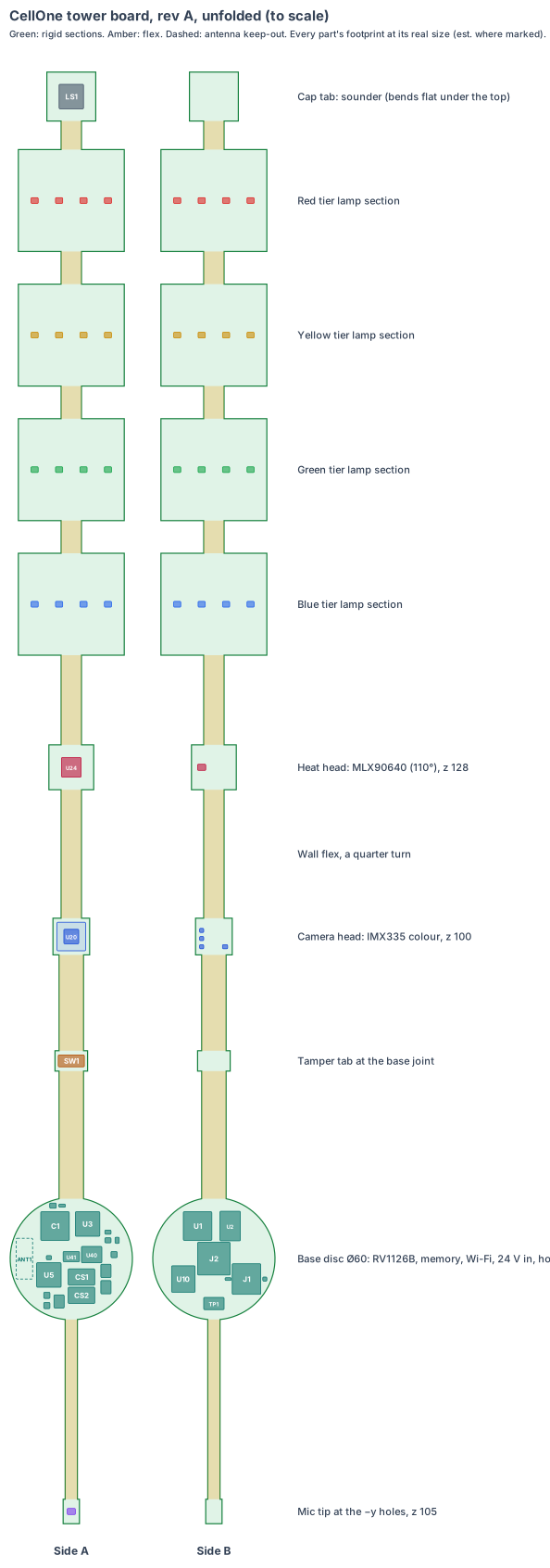
The board is code (hardware/pcb/cellone-board.mjs). It writes the KiCad board file (hardware/pcb/cellone-board.kicad_pcb), the parts list (cellone-board-parts.csv) and this drawing, and checks every part:
- every part sits inside its section with a 0.3 mm edge margin, and no two parts overlap on the same side;
- the camera’s 45° axis leaves the wall through the middle of the camera window (z 100 mm), and the lens rim and holder corners stay 0.5 mm inside the wall (checked in 3D, rev T); the mic at the mic holes (z 105) and the tamper switch at the joint between the base and the sensor tier (z 79);
- the flex round the wall and the spine into the centre are long enough for their paths, with slack;
- each lamp section stands clear inside its own tier and passes edgewise through the plate slots.
KiCad design rule check: 0 violations, 0 unconnected items (KiCad 10, 3 Nov 2026). Each part is drawn at its real size, as a placeholder outline until its full footprint is added.
Sizes come from the tower CAD (cad/cellone-cad.mjs, rev A: Ø70 × 446 mm, 32 mm inside radius, an 80 mm base, a 66 mm sensor tier, four 66 mm lamp tiers and a 36 mm cap) and the chip datasheets. Numbers marked est. are estimates.
1. The shape: one board, through the whole tower
Unfolded, the board is a 712 mm spine of rigid and flexible sections:
| Section | Type | Size (mm) | Where it sits in the tower | What is on it |
|---|---|---|---|---|
| Mic tip | rigid, 2 layers | 8 × 12 | on the −y wall behind the mic holes, z 105 | the digital mic |
| Mic flex | flex, 2 layers | 6 × 88 | up the −y wall from the disc | the mic’s clock and data |
| Base disc | rigid, 8 layers (HDI) | Ø60 | flat on a 3 mm aluminium floor plate, z 8 | RV1126B, 1 GB memory, 8 GB storage, power, Wi-Fi/Bluetooth and antenna, the M12 machine socket, 24 V input and hold-up, tier inputs, lamp drivers and fall-back, motion sensor, security chip, ID chip |
| Riser | flex, 2 layers | 12 × 120 | up the +y wall to the tamper tab, then in and up to the camera head (rev T) | the camera’s 2-lane signal, power and control |
| Tamper tab | rigid, 2 layers | 16 × 10 | on the riser at the base joint, z 74–84 | the tamper switch |
| Camera head | rigid, 4 layers | 18 × 18 | on the camera’s axis, centre z 119, tilted 45° down, so the axis leaves through the middle of the window (z 100) (rev T) | the colour camera chip, its lens holder and regulators |
| Wall flex | flex, 2 layers | 10 × 63 | a quarter turn round the inside wall, +y to +x | the heat camera’s I²C pair and power |
| Heat head | rigid, 4 layers | 22 × 22 | behind the heat window, z 128, tilted 15° down | the heat-camera chip |
| Centre spine | flex, 2 layers | 10 × 44, then 10 × 16 between tiers | into the tower’s centre, up through each tier’s plate | 5 V, ground, the four lamp lines and the sounder |
| Lamp sections (4) | rigid, 2 layers | 52 × 50 each | standing on the centre line in each lamp tier | 8 LEDs of the tier’s colour, 4 on each face |
| Cap tab | rigid, 2 layers | 24 × 24 | bends flat under the cap’s top | the sounder under the sound holes |
Why this shape:
- The tower’s inside is Ø64, so a Ø60 disc lies on the floor with 2 mm all round for the shell’s ribs.
- The camera and heat windows are in the sensor tier’s wall, so the camera and heat chips sit on small rigid heads right behind them, joined to the disc by the board’s own flex.
- The lamps sit on the centre line, so each lens is lit evenly from inside, as in a plain tower.
Two changes to the tower CAD (made in rev T, 3 Nov 2026; nothing is bought for them):
- Each tier’s plate gets a 56 × 6 mm slot in place of its Ø14 cable hole. At the factory, the tiers slide down over the board edgewise (the lamp sections are 52 mm wide and 5.4 mm thick with their LEDs), then the stack is closed with two security screws (est.).
- The tower is one sealed unit on the board build. Tiers no longer twist off on the machine; a damaged tower swaps whole on its M12 lead in about a minute, and lenses are changed at our bench. This removes every spring contact, which was the weak point under machine vibration. A rib on the sensor tier presses the tamper switch.
2. What is on the base disc
The same V1 core as CricketOne (chip, memory, storage, power layout and software image). Only what is different for a tower on a machine is described here.
| Ref | Part | Size (mm) | Side |
|---|---|---|---|
| U1 | Rockchip RV1126B-P, 0.65 mm-pitch ball package; a thermal pad joins it to the aluminium floor plate | 14 × 14 | down |
| U2 | LPDDR4X memory, 1 GB, next to U1 | 10 × 14.5 | down |
| U10 | eMMC storage, 8 GB industrial | 11.5 × 13 | down |
| J2 | M12 8-pin A-coded male PCB socket, rear mount through the base floor (Murrelektronik 7000-R2118-11A2400 class) | 16 × 16 (est.) | down |
| J1 | microSD slot, development boards only | 14 × 15 | down |
| TP1 | factory pads: USB for writing software, debug serial, boot, power rails | 10 × 6 | down |
| U3 | power regulators for the chip’s core, AI engine, logic, memory and I/O, from 5 V | 12 × 12 zone | up |
| U41 | 24 V input: 33 V surge suppressor, reverse-polarity protection, fuse | 8 × 5 zone | up |
| U40 | TI LMR36015 buck, 4.2–60 V in, to 5 V | 10 × 8 zone | up |
| U42, CS1, CS2 | TI TPS61094 supercapacitor charger and booster with 2 × 3.3 F capacitors (est.) | 3 × 3; 2 × 13 × 8 | up |
| U44, U45 | 2 × TI ISO1212 dual isolated 24 V inputs (IEC 61131-2 types 1, 2, 3) | 5 × 6.5 each | up |
| U46, U47 | TI TPS3431 watchdog and a quad 2-to-1 logic switch: the lamp fall-back | 3 × 3; 5 × 6.4 | up |
| U48 | 4-channel constant-current LED driver and the sounder driver | 3 × 3 (est.) | up |
| U5 | AMPAK AP6256 Wi-Fi 5 + Bluetooth 5 module (already certified) | 12 × 12 | up |
| ANT1 | chip antenna in an 8 × 20 mm keep-out at the disc’s edge | up | |
| U7 | LSM6DSOX motion sensor (cycles, knocks, tower strikes) | 3 × 2.5 | up |
| U8 | ATECC608B security chip (signs every call) | 3 × 2 | up |
| U9 | ID chip: product, board version, serial, calibration | 2 × 3 | up |
What the CellOne-only blocks do:
- Tier inputs, read only. The controller’s four tier lines enter through the M12 socket and are read through isolated inputs. Nothing on the board can drive a line back to the machine’s controller.
- Lamp fall-back. If the brain stops answering the watchdog, the logic switch hands each lamp driver back to its own controller line, so the tower lights exactly as a plain tower does.
- Hold-up. When the machine is switched off, the supercapacitors keep the brain alive about 2 s (est.) to sign a “power off” event and close its files.
Every board boots our software from the microSD card (J1, a hinged, latched socket fitted on every board; design review, 4 Nov 2026). Wi-Fi updates write to the card with two system copies, so a bad update rolls back by itself; the eMMC ships empty, so the card always starts first (Rockchip tries the eMMC before the card).
3. The cameras and the mic, built on the board
- Colour camera (U20): the Sony IMX335LQN-C (5 MP colour, 88-pin CSP, 7.3 × 7.1 mm) is soldered on the camera head, under an M12 lens holder with a wide lens of about 100–110° (est.). It reads dials with coloured bands, the part bin and the operator side at 2 frames a second. A driver is already in mainline Linux. Its 2.9, 1.8 and 1.2 V regulators and its clock sit on the back of the head.
- Heat camera (U24): the Melexis MLX90640ESF-BAA (32 × 24 pixels, 110° × 75°) in its TO-39 can (Ø9.3 mm), with its leads soldered through the heat head behind the heat window. Correction: our first board sheet named the BAB version, which has the narrow 55° × 35° lens. The CAD’s view checks and the bench breakout (Adafruit 4469) use the 110° lens, so the board takes the BAA.
- Mic (MK1): the Infineon IM69D130 digital MEMS mic (4 × 3 mm, PDM output), bottom port over the mic holes. The RV1126B reads it directly.
- No camera cable, harness or connector joins them to the brain. The board’s own flex carries every signal, which removes the reversed-cable fault that shorted our test board on 3 Nov 2026.
4. Every connection, checked
Our rule: every pair of parts that plug together is checked against both makers’ drawings and a search for known problems. No “same as CricketOne” claims.
| Joint | Type | Keyed | Locked | Check |
|---|---|---|---|---|
| Machine lead ↔ board | M12 8-pin A-coded male socket on the disc, through the base floor | yes (A-coding) | the lead’s screw nut | the only connector on the board. Pin for pin against each plain tower’s M12 pinout (WERMA KombiSIGN 71 drawing first), so the tower swaps in on the same lead; 8-pin bases differ between makers, so each supported tower model is listed. The socket’s footprint and panel seal come from the chosen maker’s drawing |
| Camera, heat camera, mic ↔ brain | the board’s own flex | n/a | one piece | none to fit or reverse |
| Brain ↔ lamps and sounder | the board’s own centre spine | n/a | one piece | no spring contacts, so vibration cannot flicker a lamp |
| Heat camera ↔ board | TO-39 leads soldered through the heat head | the can’s tab marks pin 1 | soldered | the Melexis pin drawing, pin 1 checked on the footprint |
| Tamper switch, sounder | soldered on their sections | n/a | soldered | the Omron D2F and sounder drawings |
No adapters anywhere.
5. Heat
- The RV1126B draws about 1.5–2.5 W at camera and AI load (est.). A plain LED tower draws 2–3 W in the same place.
- The problem: the tower is plastic, and it sits over a moulding machine at up to 50 °C (est.).
- The heat path: the chip faces down; a 1 mm thermal pad joins it to the 3 mm aluminium floor plate, and the tower’s three M5 bracket screws join the plate to the machine’s steel guard. The guard is the heat sink.
- The heat-camera chip sits 120 mm above the processor, on its own head, so the processor’s heat does not reach its readings.
- Rev A logs its temperature from the first power-on; the soak test runs the tower at 50 °C ambient.
6. Power budget (est.)
| Value | |
|---|---|
| Supply | the machine’s own 24 V tower feed (19.2–30 V, the IEC 61131-2 range) |
| Running (camera 2 fps, heat 2 Hz, one tier lit) | 3.0 W |
| Calling (a tier flashing and the tone) | 4.2 W |
| Machine off | 0 W; the hold-up keeps the brain alive about 2 s to sign the power-off event |
| Tier-line inputs | about 2 mA per line from the controller (the ISO1212’s current limit), less than a plain tower’s lamp |
The first rev A towers on a real machine replace these estimates.
7. Factory test (every board, every time)
- Current-limited first power-on (100 mA). A short trips in about 1 s, before anything heats.
- Every rail within ±3 %; the 24 V input at 19.2 and 30 V; a reversed lead does no harm.
- Our microSD card in, then boot: the board starts our software from the card.
- Camera: a test chart for focus, colour and exposure. Heat camera: two black plates at 35 °C and 80 °C (est.). Mic: a test tone. Each tier lit and read by a light sensor; the sounder’s level.
- Tier inputs on at 15 V and off at 5 V (IEC 61131-2 type 1). Brain held in reset: the lamps follow the tier lines. Cut 24 V: the power-off event is signed.
- Wi-Fi, motion sensor and tamper switch. The unit’s own key goes into the security chip, the ID chip is written and the label is printed. Every result is stored against the serial number.
For each rev A batch: vibration and shock on the bracket (IEC 60068-2-6 and 2-27), a 24-hour soak at 50 °C, and the tower-strike test from DESIGN.md (IK10, 20 J, est.).
8. Who makes what
| Work | Who |
|---|---|
| Board shape, parts, placement, checks, KiCad files, schematics | IEMI Labs |
| The RV1126B memory and power layout | copied from CricketOne’s V1 core once it is reviewed by an engineer experienced with Rockchip boards |
| The board (8-layer HDI disc + 4-layer heads + flex, one rigid-flex piece) | a rigid-flex maker (e.g. PCBWay) |
| Assembly with X-ray of the ball-grid chips | the same maker or a Shenzhen assembly house |
| Software: the V1 image, the IMX335 and MLX90640 drivers, the product program | IEMI Labs, on an RV1126B development kit while the board is made |
9. Cost per tower, electronics (est.)
| qty 10 (rev A) | qty 1,000 | qty 10,000 | |
|---|---|---|---|
| Chips and parts (incl. the MLX90640 and the M12 socket) | $150–180 | $85–100 | $70–82 |
| Rigid-flex board (712 mm, mostly 2-layer flex and lamp sections) | $70–130 | $12–17 | $8–11 |
| Assembly (incl. X-ray) | $30–50 | $5–7 | $3–5 |
| Per tower | $250–360 | $102–124 | $81–98 |
The heat-camera chip is the largest single cost (about $40–50 at volume, est.). The bench parts for the same jobs cost about $249 at qty 1 (bom.csv). From about 1,000 boards the single board costs less and needs no hand wiring.
10. Timeline
| When | Step |
|---|---|
| Nov 2026–Jan 2027 | CricketOne goes first: the V1 core and its software image are proven on CricketOne’s rev A |
| Nov–Dec 2026 | the IMX335 and MLX90640 running on the RV1126B development kit; the plain tower’s M12 pinout read from the makers’ drawings |
| Jan 2027 | CellOne schematics from the V1 core; placement (this drawing) into KiCad; engineer review |
| Feb 2027 | rev A made: 10 towers plus spares; bring-up on our fixture |
| Mar–Apr 2027 | rev B (fixes, the plate slots and sealed stack in the CAD), factory test software, vibration, shock, soak and strike tests |
| May 2027 | pilot towers on real machines; certification starts |
11. Still to check
- The plain towers’ M12 8-pin pinouts (WERMA, Patlite, Banner), and the M12 PCB socket’s footprint and seal from the chosen maker’s drawing.
- The IMX335’s package outline from Sony’s own drawing (7.3 × 7.1 mm here is from a secondary source), and its driver on Rockchip’s RV1126B Linux.
- The MLX90640 TO-39 pin drawing and lead spacing from the Melexis datasheet.
- Wi-Fi range from the disc’s edge just above the steel guard, through the plastic wall.
- The rigid-flex maker’s limits for a 712 mm board with an 8-layer section (est.; may be made as a panel of two joined at the disc).
- How hot the processor runs at 50 °C ambient with the steel guard as the heat sink, and the supercapacitors’ life at 50 °C.
- Light spread from 4 LEDs on each face of a centre lamp section through the plain lens, against a plain tower’s even glow.
Sources
- Sony IMX335 package 7.3 × 7.1 mm, 88-pin CSP BGA
- Sony IMX335 driver in mainline Linux
- Melexis MLX90640, TO-39 Ø9.3 (Arrow listing)
- Melexis MLX90640 (BAA 110° × 75°, BAB 55° × 35°)
- Murrelektronik M12 male receptacle, A-coded, 8-pole, rear mount
- Infineon IM69D130 MEMS mic
- TI ISO1212, isolated 24 V digital inputs
- TI LMR36015, 60 V buck
- TI TPS61094, supercapacitor charger and booster
- TI TPS3431, watchdog
- Microchip ATECC608B
- WERMA KombiSIGN 71 datasheet
- The tower, its sizes and its calls: CellOne’s design
- The V1 core this board copies: CricketOne’s board
- The camera short that started our board rule: the first stump, section 9
Design review (4 Nov 2026)
Every board is checked by the same rules (products/_shared/board-rules.mjs), one for each lesson any of our boards has taught us. The full review, with every number and its source, is on the board page. It changed this board:
- Our software starts from the microSD card on every board, in a hinged, latched socket (lesson from CricketOne: a push-push socket ejects on a knock).
- Heat camera: a 60 mm heater band at 1.5 m covers 0.7 of a heat pixel, so a failed band is called from its pixel’s fall, not seen as a shape: proved on rev A.
- Conformal coating (coolant mist and dust) asked for in the quote.
- In the tower CAD (rev T, 3 Nov 2026): the folded board is placed in the tower (cad/cellone-t-cad.mjs) and every part is checked in 3D against every tier, plate and window with 0.3 mm clearance, and against the new 3 mm aluminium floor plate under the disc (a 0.3 mm pocket under each chip on the disc’s underside, a through hole for the M12 socket). The camera lens holder and lens reached into the wall: with the chip level with the window, the 45° axis left the wall 14 mm below it. The camera head moved up and in onto the axis (centre y 12.9, z 119.1), so the axis now leaves through the middle of the window with the lens 1.1 mm inside the wall; the riser grew 40 mm (board 712 mm unfolded) and the board code checks the axis, lens rim and holder corners in 3D. The tower CAD now has the 56 × 6 slot in every plate and the 16.6 mm square floor hole for the M12 socket (changes 1 above).
- Fast lines on a solid ground plane (to prove, lesson: planes, from the CricketOne test-board layout of 4 Nov 2026): RV1126B memory; 1 camera MIPI link (100 Ω pairs); USB (90 Ω); antenna feed (50 Ω, keep-out on every layer); card lines (length-matched, no vias under the socket). Ground on the layer next to the parts (inner layer 1, supply on inner layer 2; the whole bottom of a 2-layer section), one via beside each ground and supply pad and none in pads, no copper or vias in the antenna keep-out on any layer or under the card socket, the impedance lines routed first with a test coupon. The quote asks for it; the routed board’s design rule check proves it.
The request for quote is /build/cellone-quote.
New shared rule (4 Nov 2026, from the CricketOne test-board circuit): the Wi-Fi module’s own clock. Drawing CricketOne’s circuit pin by pin found that the AP6256 Wi-Fi/Bluetooth module runs from a 37.4 MHz reference clock, which our board notes had as 26 MHz or left out. Every board with an AP6256 is now checked for a 37.4 MHz clock beside it (MEMS where the product takes knocks). On this board the AP6256 had no clock of its own on the board; Y3, a 37.4 MHz MEMS oscillator, now sits next to it on the disc (the rev T tower CAD was re-run: nothing touches a wall). The review shows it under Radio (lesson: wificlock).