KitchenOne: one circuit board of our own
What changed (4 Nov 2026). The rev A bench hood is built from bought boards joined by leads: a XIAO ESP32-S3, an Adafruit MLX90640 heat-camera board, a MAX9814 mic board, an LD2410C radar module, two NeoPixel sticks, a piezo, an ATECC608 board and a PowerBoost 1000C charger. KitchenOne now gets one circuit board of our own, like CricketOne, DampOne and ChillOne, with every chip placed straight onto it. It is the first board made with every shared design-review rule from the start.
- The chips: the ESP32-S3 certified radio module (soldered by its edge pads), a bare Melexis heat-camera chip over the hob, an Infineon 60 GHz radar chip with its antennas built in, a MEMS mic, sixteen call-light LEDs, a sounder, touch electrodes for the fascia’s touch strip, the fan speed line and lamp switch, the security chip, the tamper switch, a charger and two soldered 18650 cell holders.
- The shape: the hood’s front compartment is a long, sealed strip behind the fascia, away from the hot grease filter. So the board is a long main strip (452 × 63.6 mm, 4 layers) lying flat 8 mm above the compartment floor, side A down to the hob, and a front strip (430 × 56 mm, 2 layers) joined by a 60 mm wide flex that bends it 90° up, side A to the room, 7 mm behind the front face.
- Mains stays in the supply. The Mean Well LRS-50-5 that also feeds the hood lamps stays at the compartment’s left end; one latched lead brings 5 V to the board and takes the switched lamp feed back. The hood’s own fan takes our speed line on a second latched lead.
- The rev A bench hood stays as it is. It proves the calls and the software, which move to this board unchanged (same ESP32-S3 family).
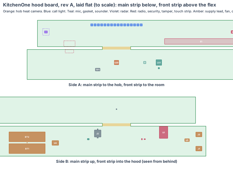
The board is code (hardware/pcb/kitchenone-board.mjs). It writes the KiCad board file (hardware/pcb/kitchenone-board.kicad_pcb), the parts list (kitchenone-board-parts.csv) and this drawing, and checks every part:
- every part sits on its strip with a 0.3 mm edge margin and no two parts overlap on the same side;
- every part’s height fits its side: 7.5 mm under the main strip, 77.5 mm above it, 6.5 mm in front of the front strip;
- the heat camera, the mic and its gasket and the sounder sit on their holes in the hood’s underside, and the radar chip, the call-light LEDs, the tamper switch and the touch electrodes on their windows in the front (within 1 mm, from cad/kitchenone-cad.mjs);
- the fold keeps the front strip inside the compartment, 7 mm behind the front face and below the ceiling, and the main strip 8.5 mm clear of the supply;
- the radio module’s antenna end is at the main strip’s front edge, with a keep-out under it and a copper-free window on the front strip in front of it;
- the radio, the power block and the supply lead are 30 mm or more from the heat camera (91 mm in this layout), so a warm board does not offset the hob readings.
KiCad design rule check: 0 violations (KiCad 10, 4 Nov 2026). Each part is drawn at its real size, as a placeholder outline until its full footprint is added. Numbers marked est. are estimates.
1. The shape: a main strip and a front strip in the hood’s front compartment
| Value | |
|---|---|
| Main strip | 452 × 63.6 mm, 1.6 mm, rigid, 4 layers (ground and power inside); x −190 to 262, y 404 to 467.6 (y out from the wall) |
| Where | flat on standoffs, side A 8 mm above the compartment floor (canopy underside 1,580 mm above the floor, 700 mm above the hob) |
| Flex | 60 × 6 mm, 2 layers, from the main strip’s front edge; bent 90° up, radius 3.8 mm |
| Front strip | 430 × 56 mm, 0.8 mm, rigid, 2 layers; side A 7 mm behind the front face, from 1,594 to 1,650 mm above the floor |
Why this shape: the compartment is the only part of the hood out of the hot, greasy air path. Its floor carries the holes that look and listen down at the hob, and its front carries the windows to the room. One strip on the floor and one bent up behind the front reach every hole and window without a second board.
Nothing in the hood CAD changes for this board. Every hole and window it uses is already in cad/kitchenone-cad.mjs rev A (Ø14 heat window, mic port, tone holes, radar window with a 1.5 mm skin, opal slot, tamper hole, touch strip). The CAD alignment with the board inside the hood (rev T) is the next step.
2. What is on the board
The S1 sensor core (radio module, radar chip, power block, security chip and software), in KitchenOne’s shape.
| Ref | Part | Size (mm) | Where |
|---|---|---|---|
| U1 | Espressif ESP32-S3-WROOM-1-N8R8: ESP32-S3, 8 MB flash, 8 MB PSRAM, PCB antenna; FCC and CE certified; soldered by its edge pads, antenna at the main strip’s front edge | 18 × 25.5 × 3.1 | main, top |
| U2 | Microchip ATECC608B security chip (signs every call) | 2 × 3 | main, top |
| U9 | ID chip: product, board version, serial, calibration | 2 × 3 | main, top |
| J1 | Molex Micro-Fit 3.0 4-way vertical header, latched: 5 V and ground from the LRS-50-5, switched lamp feed (exact part number to confirm) | 13 × 10 × 9.5 (est.) | main, top |
| J3 | the same header for the hood fan: PWM, tach, ground, spare | 13 × 10 × 9.5 (est.) | main, top |
| U5 | fan PWM output, tach input, lamp MOSFET | 10 × 6 zone | main, top |
| U4 | 5 V input protection, TI BQ24074 charger with power path and NTC input, TI TPS63020 3.3 V buck-boost | 14 × 10 zone | main, top |
| BT1, BT2 | two Keystone 1042-class SMT holders for Samsung INR18650-35E cells | 77 × 21 × 21 (est.) | main, top |
| RT1 | 10 k NTC thermistor between the cells, read by the charger | 0603 | main, top |
| J2 | hinged, latched microSD socket: our software starts from the card | 14 × 15 × 1.9 | main, top |
| MK1 | Infineon IM69D130 MEMS mic, bottom port over a Ø1 hole in the board | 4 × 3 × 1.2 | main, top |
| U20 | Melexis MLX90640ESF-BAA heat-camera chip (32 × 24, 110 × 75°), TO39 can, looking straight down at the hob through the Ø14 window | Ø9.4 × 6.6 (est.) | main, hob side |
| GK1 | silicone sound gasket from the board hole to the mic port | Ø5 × 8 (est.) | main, hob side |
| LS1, Q1 | 12 × 12 mm SMD sounder over the tone holes, and its driver | 12 × 12 × 3 (est.) | main, hob side |
| TP1 | factory pads: USB, serial, boot, enable, rails | 10 × 6 | main, hob side |
| U3 | Infineon BGT60TR13C 60 GHz radar chip, antennas in the package, with a 14 × 14 mm keep-out, behind the radar window | 6.5 × 5.0 × 0.9 | front, room side |
| D1–D16 | 16 RGB LEDs with built-in drivers (5050, WS2812B class) behind the opal slot | 5 × 5 × 1.6 | front, room side |
| SW1 | Omron D2F-01 tamper switch, pressed through the Ø4 hole by the fascia’s boss | 12.8 × 5.8 × 6.5 | front, room side |
| E1 | four copper touch electrodes behind the fascia’s touch strip (lamp, fan, silence, call) | 156 × 12 | front, room side |
| U7 | level shifter for the LED data line | 2 × 2 | front, back |
What is different for a range hood:
- One heat-camera chip over the hob. The bare MLX90640 is the same sensor as the Adafruit board without the breakout, soldered through the board over the Ø14 window.
- Radar on the board. The LD2410C was a module on pins; the BGT60TR13C has its antennas in its package and sees the room through the 1.5 mm fascia skin.
- A mic chip in place of a mic board. It hears whistles and the home’s own smoke and gas alarms as sound patterns; nothing is recorded.
- Backup cells on the board. The PowerBoost board and loose cells become a charger chip and two soldered holders with a thermistor: a gas hob keeps burning in a power cut, so the hood keeps watching.
- A touch strip. The fascia’s recessed strip reads through four copper pads on the front strip, so lamp, fan and silence need no buttons or holes.
3. Every connection, checked
Our rule: every pair of parts that join is checked against both makers’ drawings and a search for known problems. No “same as DampOne” claims.
| Joint | Type | Keyed | Locked | Check |
|---|---|---|---|---|
| Supply lead ↔ board | Molex Micro-Fit 3.0 4-way receptacle on the lead, header J1 | the housing’s polarising ribs | positive latch | To check: the header part number, footprint and pin order from Molex’s drawing; the crimp against the wire size; the LRS-50-5’s screw terminals at the other end (Mean Well drawing) |
| Fan lead ↔ board | the same header type, J3 | polarising ribs | positive latch | To check: the hood fan’s own speed input and connector are the fan maker’s; we make no claim until we have its drawing |
| Radio module ↔ board | castellated edge pads, reflow soldered | outline and pin 1 mark | soldered | Espressif’s footprint and antenna keep-out from the WROOM-1 datasheet and hardware design guide |
| Heat-camera chip ↔ board | TO39 leads through the board, soldered | the can’s tab | soldered | Melexis land pattern and lead pitch from the MLX90640 datasheet |
| Front strip ↔ main strip | a 2-layer flex, part of the board | built in | built in | no connector. Bend radius 3.8 mm (90° over 6 mm) against the maker’s minimum for a static bend (to confirm) |
| Cells ↔ board | Keystone SMT holders, reflow soldered; cells held by the holders’ springs and a strap | the holders’ polarity marks | strap | To check: the holder’s outline and pad drawing, and its spring force against a 30 g drop of the hood front (est.) |
| Radar, mic, security, charger chips ↔ board | soldered | pin 1 marks | soldered | each maker’s land pattern; the mic’s port hole and gasket from Infineon’s IM69D130 guidance |
No adapters, no plug-in modules and no ribbons inside.
4. Heat
- The board draws about 0.9 W watching (est., section 5). The problem is the hood, not the board: steam and hot air rise round the canopy while cooking, so the compartment is counted at 55 °C (est.).
- The ESP32-S3 at 0.5 W reaches about 65 °C (est.), inside its 85 °C rating.
- The cells sit at the compartment’s right end, away from the heat window. Charging holds above 45 °C (RT1 on the BQ24074) and resumes when cooking ends; the cells are rated to 60 °C while discharging.
- The heat camera reads the hob, not the board: the radio, the power block and the supply lead are 91 mm or more from its can.
- Rev A logs the compartment temperature over a real gas hob at full boil for an hour.
5. Power budget (est.)
| Value | |
|---|---|
| Supply | 5 V from the hood’s Mean Well LRS-50-5 (50 W), down the latched lead |
| Watching (Wi-Fi, radar, heat camera at 2 Hz, mic) | 0.9 W |
| Charging the cells | 1.5 W more, until full |
| Hood lamps (switched by the board, fed by the supply) | about 6 W |
| Power cut (heat camera at 0.5 Hz, Wi-Fi only for alerts) | 0.6 W from two cells: about 25 h, aged to 80 % |
6. Factory test (every board, every time)
- Current-limited first power-on (100 mA). A short trips in about 1 s, before anything heats.
- Every rail within ±3 %; reverse 5 V does no harm. Charger: charge current, the thermistor’s hold at a hot and a cold resistor, power-path switch-over with 5 V removed.
- Our small loader flashed over the USB pads; our microSD card in, then boot: the loader starts our program from the card.
- Heat camera: a warm and a cold plate under the window position; every pixel answers. Radar: a moving plate at 1 m and 3 m. Mic: a test tone and a smoke-alarm pattern. Each LED colour read by a light sensor; the sounder’s level; each touch pad.
- Fan PWM out and tach in on a test fan; the lamp switch on a test load. The tamper switch opened and closed. The flex bent to 90° and back once, then the front strip checked again.
- Wi-Fi to the fixture. The unit’s own key goes into the security chip, the ID chip is written and the label is printed. Every result is stored against the serial number.
For each rev A batch: radio pre-scan (FCC Part 15, UK and EU radio rules, and the 60 GHz radar rule), a 24-hour soak at 55 °C in steam, and the hood’s own electrical safety pre-checks.
7. Who makes what
| Work | Who |
|---|---|
| Board shape, parts, placement, checks, KiCad files, schematics | IEMI Labs |
| The S1 core circuit (radio module, radar and security chips, power block) | copied from DampOne’s board |
| The board (4-layer main strip, 2-layer flex and front strip) | a maker that builds rigid-flex boards (see the makers list on the boards page) |
| Assembly, including the through-board heat-camera can and the cell holders | the same maker or a Shenzhen assembly house |
| Software: the kitchen program, the hob heat model, the radar presence code, the whistle and alarm sounds | IEMI Labs, on the bench hood and the makers’ evaluation boards while the board is made |
8. Cost per hood, electronics (est.)
| qty 10 (rev A) | qty 1,000 | qty 10,000 | |
|---|---|---|---|
| Chips and parts (incl. the heat-camera chip, radar chip and cell holders; cells extra) | $80–100 | $55–65 | $45–55 |
| Board (rigid-flex: 452 mm main strip, 430 mm front strip) | $35–55 | $8–12 | $6–8 |
| Assembly | $15–25 | $3–5 | $2–3 |
| Per hood | $130–180 | $66–82 | $53–66 |
The heat-camera chip is the biggest single part (about $30–35 at volume, est.). The two long strips make the board larger than it needs to be in area; a rev B option is a shorter front strip with the tamper switch moved next to the radar, once the hood CAD can move the tamper hole.
9. Timeline
| When | Step |
|---|---|
| Nov–Dec 2026 | the radar, mic and bare heat-camera chips on their makers’ evaluation boards beside the bench hood; the hob heat model re-checked on their data |
| Jan 2027 | KitchenOne schematics from the S1 core; placement (this drawing) into KiCad; review |
| Feb 2027 | rev A made: 10 boards plus spares; bring-up on our fixture |
| Mar 2027 | rev B (fixes), factory test software, radio pre-scan |
| Apr–May 2027 | pilot kitchens; certification starts |
10. Still to check
- The bare MLX90640ESF-BAA can’s exact outline, lead pitch and land pattern from the Melexis datasheet (here Ø9.4 × 6.6, est.).
- The Micro-Fit 3.0 header part number, footprint and pin order, and the hood fan’s own speed input and connector.
- The Keystone 18650 SMT holder’s outline and pads (here 77 × 21 × 21, est.).
- The flex’s minimum static bend radius from the chosen maker against the 3.8 mm used here.
- Wi-Fi range from inside the steel hood, out through the fascia, to a home router (measured on rev A).
- The compartment temperature over a gas hob at full boil, and the cells’ temperature in it.
- The CAD alignment (the board in the hood CAD, every part checked in 3D, rev T) and the product page’s 3D board model, as done for DampOne.
Sources
- Espressif ESP32-S3-WROOM-1 datasheet (18 × 25.5 × 3.1)
- Melexis MLX90640, 32 × 24 thermal sensor (BAA: 110 × 75° view)
- Infineon BGT60TR13C, 60 GHz radar, antennas in package, 6.5 × 5.0 × 0.9
- Infineon IM69D130 MEMS microphone
- TI BQ24074 charger with power path
- TI TPS63020 buck-boost converter
- Keystone 18650 cell holders
- Samsung INR18650-35E specification
- Molex Micro-Fit 3.0 connectors
- Microchip ATECC608B
- Omron D2F datasheet
- Mean Well LRS-50 datasheet
- The hood, its sizes and its calls: KitchenOne’s design
- The board platform: our own boards
Design review (4 Nov 2026)
Every board is checked by the same rules (products/_shared/board-rules.mjs), one for each lesson any of our boards has taught us. KitchenOne’s board was made with every rule from the start, so nothing had to be fixed. The full review, with every number and its source, is on the board page. It shows:
- Heat camera pixels: a 16 cm pan on the farthest burner fills 3.5 px; a lit burner with nothing on it (the 9 cm flame ring at 0.76 m) fills 2.0 px against a 1.5 px need, because a flame only has to be found, not measured.
- Power cut: two cells give about 25 h of alerts aged to 80 % (to prove on rev A; target 24 h), since a gas hob keeps burning when the power goes.
- Cells in a hot hood: charging holds above 45 °C and resumes after cooking (to prove over a real hob).
- The latched microSD (J2) is fitted, and our software starts from it.
- Conformal coating against steam and grease is asked for in the quote.
- Wi-Fi from inside the steel hood is measured on rev A; the antenna sits under the plastic fascia with a copper-free window in front of it.
- The tamper switch against the fascia boss is checked with the printed fascia on rev A.
- Fast lines on a solid ground plane (to prove, lesson: planes, from the CricketOne test-board layout of 4 Nov 2026): USB (90 Ω); antenna feed (50 Ω, keep-out on every layer); card lines (length-matched, no vias under the socket). Ground on the layer next to the parts (inner layer 1, supply on inner layer 2; the whole bottom of a 2-layer section), one via beside each ground and supply pad and none in pads, no copper or vias in the antenna keep-out on any layer or under the card socket, the impedance lines routed first with a test coupon. The quote asks for it; the routed board’s design rule check proves it.
The request for quote is /build/kitchenone-quote.
New shared rule (4 Nov 2026, from PumpOne): antennas outside metal boxes. A radio inside a closed metal enclosure now fails the review unless its antenna is outside the metal. This board’s antennas already use the strip’s front edge under the plastic fascia, so the check passes and the review names the window (lesson: enclosure).