RacketOne: one circuit board of our own in each net post
What changed (3 Nov 2026). The rev O net posts are built from bought boards: a Raspberry Pi Zero 2 W with the AI Camera on a ribbon, a XIAO ESP32-S3 Sense as the kitchen camera, a XIAO nRF52840 Sense for the mic and motion, an LD2450 radar module, an e-paper board, a NeoPixel stick, an ATECC608 breakout and a PowerBoost charger, and on the home post a DPTechnics Walter, all joined by wires. RacketOne now gets one circuit board of our own in each post, like CricketOne and AthleticsOne, with every chip placed straight onto it. An assembly house makes and tests it.
- The chips: Rockchip’s RV1126B processor with its memory and storage, Wi-Fi and Bluetooth, two OV9281 global-shutter camera chips (one for the lines on the post’s own half, one low for the pickleball kitchen), an ESP32-S3 module that stays awake when the processor sleeps, Infineon’s 60 GHz radar chip, the e-paper panel’s own tail soldered on, eight call-lamp LEDs, a sounder, two sealed key switches, the motion sensor and mic, the security chip, and the battery charger, protection and gauge. The home post adds the LTE-M modem with a soldered eSIM.
- The shape: the post is a round tube, 72.2 mm inside, so the board is one spine standing 22 mm in front of the post’s middle, with side A to the court face where every window is. A flat tab sits on the cells in the foot; small turned heads carry the two cameras; two small tabs fold round to the team keys on each face of the net.
- Both posts carry the same board. The away post leaves the 3 home-only parts unfitted, so there is one design, one test and one software image.
- The rev O bench posts stay as they are. They prove the calls and the software, which move to this board.
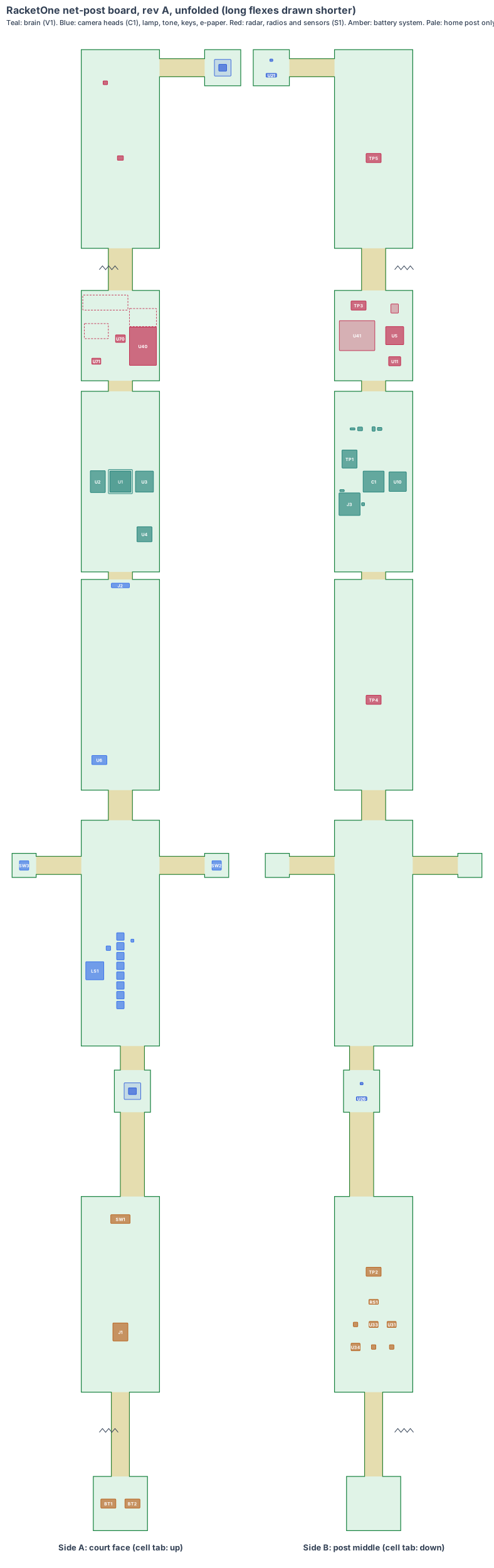
The board is code (hardware/pcb/racketone-board.mjs). It writes the KiCad board file (racketone-board.kicad_pcb), the parts list (racketone-board-parts.csv) and this drawing, and checks every part:
- every part sits inside its section with a 0.3 mm edge margin, no two parts overlap on the same side, and every part’s top corners stay at least 0.5 mm inside the round post (radius 36.1 mm);
- the call-lamp LEDs sit inside the 12 × 54 lamp strip (z 380), the sounder under the tone holes, the mic under its port (z 940), the charge socket at its hole (z 140), the tamper switch under the service hatch, and the e-paper tail pads beyond the end of the panel, with every part under the panel clear of it;
- the radar chip and every antenna (Wi-Fi/Bluetooth, ESP32-S3, LTE-M) sit behind the 50 × 60 radio window, z 770–830;
- both cameras look out through their windows: each lens tip, lens rim and head corner stays 0.5 mm inside the tube (checked in 3D, with the head’s tilt and thickness), the optical axis leaves through the middle of its window (kitchen 2.7 mm from centre in a Ø12 window, line 1.5 mm in a Ø16 window), and each lens covers the field of view the post CAD’s camera checks need (kitchen 69° × 46° for 60° × 45°; line 82° × 57° for 66.3° × 52.3°, est.);
- the RV1126B sits on solid court-face wall (z 650–760, between the e-paper and radio windows), and its heat block stack meets the wall;
- the board stays clear of the net cord’s tie-off at z 1,070, and every flex is long enough for its path.
KiCad design rule check: 0 violations, 0 unconnected items (KiCad 10, 3 Nov 2026). Each part is drawn at its real size, as a placeholder outline until its full footprint is added.
Sizes come from the post CAD (cad/racketone-cad.mjs, rev O: 6063-T6 round tube Ø76.2 × 2.0, top 1,090 mm, foot 150 mm into the ground sleeve) and the chip datasheets. Numbers marked est. are estimates.
1. The shape: one board, up the whole post
| Section | Type | Size (mm) | Where it sits | What is on it |
|---|---|---|---|---|
| Cell tab | rigid, 2 layers | 36 × 36 | flat on the four cells’ top ends, z −62 | nickel-strip pads for the cell pack and its thermistor |
| Cell flex | flex, 2 layers | 12 × 176 | up the cell bay to the foot | power and the gauge lines |
| Foot section | rigid, 4 layers | 52 × 130 | z 100–230 | charger, protection, gauge, 5 V boost, the processor’s power switch; the M8 charge socket and the tamper switch on the court face |
| Kitchen head | rigid, 4 layers | 24 × 28 | z 286–314, turned 16° to its own half, tilted 3° down | OV9281 camera chip, M8 lens holder with a 2.8 mm lens, its regulators and clock |
| Lower section | rigid, 4 layers | 52 × 150 | z 330–480 | 8 call-lamp LEDs behind the strip, the sounder under the tone holes |
| Key tabs | flex then rigid, 2 layers | 30 × 12 flex, 16 × 16 tab, each side | fold round to the north and south key holes, z 450 | a sealed key switch on each |
| Panel section | rigid, 4 layers | 52 × 140 | z 500–640, behind the e-paper panel | the panel’s tail pads and booster |
| Brain | rigid, 8 layers (HDI) | 52 × 120 | z 645–765, RV1126B under a heat block to the court-face wall | RV1126B, 1 GB memory, 8 GB storage, power, security chip, ID chip |
| Radio section | rigid, 4 layers | 52 × 60 | z 772–832, behind the radio window | radar chip, ESP32-S3 module and every antenna (side A); Wi-Fi/Bluetooth module, LTE-M modem and eSIM (side B) |
| Upper section | rigid, 4 layers | 52 × 132 | z 880–1,012 | mic, motion sensor |
| Line-camera head | flex then rigid, 4 layers | 30 × 12 flex, 24 × 24 head | behind the window on the half’s face, z 1,000, turned 60° from the court face, tilted 15° down | OV9281 camera chip, M8 lens holder with a 2.2 mm lens, its regulators and clock |
The flexes between the sections are 16 mm wide (8 mm room each side of the middle). Unfolded, the board is about 1.1 m long.
Why this shape:
- In a round tube a flat board is widest through the middle, but the windows are all on the court face, and a camera or radar 36 mm behind its window would see out through a keyhole. At 22 mm forward the spine is still 52 mm wide, side A has 9–13 mm to the court face, and side B has room for the taller modules.
- The processor’s heat goes into the aluminium post through a small aluminium block machined to the tube’s curve (est.), on the one stretch of solid court-face wall between the e-paper and radio windows.
- The radar chip and every antenna face one window. The aluminium post would block radio anywhere else.
- The board stops at 1,012 mm, under the net cord, which passes into the post at 1,070 mm and ties off inside it. The motion sensor feels lets and net touches through the post.
Six changes to the post CAD (next CAD revision; nothing is bought for them):
- Every bought board comes out of the post (Pi Zero 2 W, AI Camera, both XIAOs, LD2450, e-paper board, NeoPixel stick, ATECC608 breakout, PowerBoost, and the Walter on the home post); the board takes their place.
- The tone holes and the mic port move from the back face to the court face (the tone at y −17, z 380; the mic at z 940), so their parts sit on side A at their holes.
- The radar radome slot grows from 50 × 18 to a 50 × 60 polycarbonate radio window (z 770–830): the radar chip and every antenna sit behind it.
- The service hatch moves to the court face, z 190–240, and a boss on its inside presses the tamper switch.
- The charge input becomes an M8 3-pin screw-locked socket through the court face at z 140 under a tethered cap (the PowerBoost’s USB socket was inside the post).
- Each key hole gets a stainless plunger, sealed in the hole, that presses the key switch on its tab (was a 16 mm panel button on wires).
2. What is on each section
The brain uses the same V1 core as CricketOne (chip, memory, storage, power layout and software image). Both camera heads use the same C1 camera chip. The radio section uses the S1 core’s ESP32-S3 module and radar chip, as on RoomOne. Only what is different for a net post is described here.
| Ref | Part | Size (mm) | Section, side | Post |
|---|---|---|---|---|
| U1, HB1 | Rockchip RV1126B-P, under a 16 × 16 aluminium heat block to the court-face wall | 14 × 14 | brain, A | both |
| U2, U10 | LPDDR4X 1 GB; eMMC 8 GB industrial | 10 × 14.5; 11.5 × 13 | brain, A; B | both |
| U8 | ATECC608B security chip (signs every call) | 3 × 2 | brain, B | both |
| U70 | Infineon BGT60TR13C 60 GHz radar chip, antennas in the package | 6.5 × 5 × 0.9 | radio, A | both |
| U40, ANT2 | Espressif ESP32-S3-WROOM-1-N8R8 (certified), the always-on brain | 18 × 25.5 × 3.1 | radio, A | both |
| U5, ANT1 | AMPAK AP6256 Wi-Fi 5 + Bluetooth 5 (certified); chip antenna in a 16 × 10 keep-out | 12 × 12 | radio, B; A | both |
| U41, U42, ANT3 | Quectel BG95-M3 LTE-M modem, MFF2 eSIM, 30 × 3 chip antenna | 23.6 × 19.9 × 2.2 | radio, B (antenna A) | home |
| U25, LH2 | OmniVision OV9281 kitchen camera chip, M8 lens holder with a 2.8 mm lens | 5.24 × 4.46; 11 × 11 | kitchen head, A | both |
| U20, LH1 | OmniVision OV9281 line camera chip, M8 lens holder with a 2.2 mm lens | 5.24 × 4.46; 11 × 11 | line head, A | both |
| J2, U6 | 2.13 in e-paper panel’s own tail soldered to 24 pads by hot bar; the panel maker’s booster | 12 × 3 pads | panel, A | both |
| LS1, D1–D8 | 12 × 12 magnetic sounder under the tone holes; 8 WS2812B-class LEDs behind the lamp strip | 12 × 12 × 3; 5 × 5 | lower, A | both |
| SW2, SW3 | sealed IP67 key switches (C&K KSC class), one per team | 6.2 × 6.2 × 5 (est.) | key tabs, A | both |
| MK1, U7 | Infineon IM69D130 mic under its port; ST LSM6DSOX motion sensor | 4 × 3; 3 × 2.5 | upper, A | both |
| U30–U33 | TI BQ24074 charger with power path, cell protection, gauge, input protection | 3 × 3 and zones | foot, B | both |
| U34, U35 | TI TPS61023 5 V boost for the lamp and tone; the processor’s load switch | zones | foot, B | both |
| J1 | M8 3-pin A-coded PCB socket through the court face | 10 × 12 (est.) | foot, A | both |
| SW1 | Omron D2F-01 tamper switch under the service hatch | 12.8 × 5.8 × 6.5 | foot, A | both |
All 63 parts, with sizes, heights and sources, are in the parts list.
What the RacketOne-only blocks do:
- Two brains, one board. The ESP32-S3 is always on. It keeps the score from the keys, draws the e-paper, reads the radar for court use, no-shows and lights-off, feels lets through the motion sensor, logs noise, and links the two posts over Bluetooth. It switches the RV1126B on for a match. Then the RV1126B reads both cameras and makes the line, service and kitchen calls.
- Two cameras, one processor. The line camera looks down its own half’s sidelines, service line and centre T; the kitchen camera sits low and sees the whole 6.1 m kitchen line. The OV9281’s global shutter keeps a fast ball and a foot sharp. This replaces the IMX500 AI camera, the Pi Zero 2 W and the XIAO ESP32-S3 Sense.
- No camera cable, harness or breakout. The board’s own flex carries every signal from both cameras, the radar, the radios, the keys and the sensors.
3. Every connection, checked
Our rule: every pair of parts that join is checked against both makers’ drawings and a search for known problems. No “same as CricketOne” claims.
| Joint | Type | Keyed | Locked | Check |
|---|---|---|---|---|
| Charge lead ↔ post | M8 3-pin A-coded female PCB socket in the court face, tethered cap | yes (A-coding) | the lead’s screw nut | the only connector on the post. The socket’s footprint, panel seal and the lead’s pinout come from one maker’s drawing for both halves (still to check 1). |
| E-paper panel ↔ board | the panel’s own tail, soldered by hot bar | the tail’s one-sided pads | soldered | no connector, so it cannot be put in reversed (the fault that shorted our CricketOne test board on 3 Nov 2026). Pad pitch and order from the panel maker’s drawing (still to check 3) |
| Key plunger ↔ key switch | the stainless plunger presses the switch; nothing electrical crosses | the plunger only fits its hole | sealed in the hole | plunger travel against the switch’s travel and force from the switch maker’s drawing (still to check 2) |
| Cameras, radar, radios, keys, lamp, sensors ↔ brain | the board’s own flex | n/a | one piece | none to fit or reverse: this removes the camera ribbon and every breakout wire |
| Cells ↔ cell tab | nickel strips spot-welded to the cells, soldered to the tab | the + and − pads are 16 mm apart and marked | soldered | Samsung 35E drawing; the pack is welded and tested before it is soldered |
| Tamper switch | soldered on the foot section | n/a | soldered | the Omron D2F drawing |
No adapters anywhere.
4. Heat
- The RV1126B draws about 1.5–2.5 W with two cameras and the calls running (est.), but only in a match. The ESP32-S3 and radar draw well under 0.5 W the rest of the time (est.).
- The problem: a green post on a hard court in full sun can reach about 60 °C (est.), and the chip is 13 mm from the wall.
- The heat path: a 0.5 mm pad on the chip, a 16 × 16 aluminium block machined to the tube’s curve, and a 1 mm pad onto the 2 mm aluminium wall; the 1.24 m post spreads it. The post is the heat sink.
- Rev A logs its temperature from the first power-on. The soak test runs the post at 50 °C ambient under a sun lamp.
5. Power budget (est.)
| Home post | Away post | |
|---|---|---|
| Pack | 4 × Samsung INR18650-35E, 1S4P, 14 Ah, about 50 Wh | the same |
| Idle (ESP32-S3 awake, radar, e-paper still) | 0.25 W | 0.2 W |
| Match (RV1126B, two cameras, every call on) | 2.6 W | 2.5 W |
| Call (lamp flash and tone, 2 s) | +1.0 W | +1.0 W |
| Match play on a full charge | about 16 h | about 17 h |
The rev O bench posts draw about 3.1 W in a match with every call on, about 13.8 h a charge. The single board is lower because one processor reads both cameras and the LTE-M modem sleeps between messages (est.). The first rev A posts on a court replace these estimates.
6. Factory test (every board, every time)
- Current-limited first power-on (100 mA). A short trips in about 1 s, before anything heats.
- Every rail within ±3 %; charge from the M8 socket at 5 V; a reversed lead does no harm.
- Our ESP32-S3 image flashed over the factory pads; our microSD card in, then boot: the board starts our software from the card (MEMS clocks and the latched card socket from the design review, 4 Nov 2026).
- Both cameras: a test chart for focus and exposure at 120 frames a second. The lamp read by a light sensor; the sounder’s level; the mic with a test clap; the e-paper’s test pattern; both key switches.
- Radar: a moving target at 3 m in a test box. Radios: Bluetooth link to a test post, Wi-Fi to a test phone, LTE-M on a test network (home).
- Motion sensor and tamper switch. The unit’s own key goes into the security chip, the ID chip is written and the label is printed. Every result is stored against the serial number.
For each rev A batch: the ball and body strike tests from DESIGN.md “Impact” with the board fitted, a drop of the boxed post, a 24-hour soak at 50 °C and an IPX4 spray (est.).
7. Who makes what
| Work | Who |
|---|---|
| Board shape, parts, placement, checks, KiCad files, schematics | IEMI Labs |
| The RV1126B memory and power layout | copied from CricketOne’s V1 core once an engineer experienced with Rockchip boards has reviewed it |
| The board (8-layer HDI brain + 4-layer sections + flex, one rigid-flex piece about 1.1 m unfolded) | a rigid-flex maker; see who can make it |
| Assembly with X-ray of the ball-grid chips | the same maker or a Shenzhen assembly house |
| The heat block and key plungers | a local machine shop with the post (est.) |
| Software: the V1 image, the two-camera OV9281 driver, the ESP32-S3 program, the calls | IEMI Labs, on an RV1126B development kit while the board is made |
8. Cost per court (pair of posts), electronics (est.)
| qty 10 (rev A) | qty 1,000 | qty 10,000 | |
|---|---|---|---|
| Chips and parts, both posts (incl. 4 camera chips, 2 radar chips and the LTE-M modem) | $300–360 | $160–190 | $130–155 |
| Rigid-flex boards (two posts) | $180–320 | $30–42 | $21–28 |
| Assembly (incl. X-ray) | $60–100 | $10–14 | $7–10 |
| Per court | $540–780 | $200–246 | $158–193 |
The bought boards and parts for the same jobs cost about $648 a court at qty 1 (bom.csv). From about 1,000 courts our board costs well under half, and needs no hand wiring.
9. Timeline
| When | Step |
|---|---|
| Nov 2026–Jan 2027 | CricketOne goes first: the V1 core and its software image are proven on CricketOne’s rev A |
| Dec 2026–Feb 2027 | the line and kitchen calls on the RV1126B development kit with two OV9281s; the ESP32-S3 program moved from the XIAOs and the Walter |
| Mar 2027 | RacketOne schematics from the V1, C1 and S1 cores; this placement into KiCad; engineer review |
| Apr 2027 | rev A made: 5 pairs plus spares; bring-up on our fixture |
| May–Jun 2027 | rev B (fixes, the six CAD changes), factory test software, strike, drop, soak and spray tests |
| Jul 2027 | pilot courts at clubs and parks; radio certification starts |
10. Still to check
- The M8 3-pin PCB socket and its lead from one maker (Binder or Phoenix Contact), with the footprint, panel seal and pinout from the drawings of both halves, and how it sits in a curved wall.
- The sealed key switch from one maker’s drawing (size, travel, force, IP rating; 6.2 × 6.2 × 5 here is est.) and the plunger’s travel against it; a known-issues search on plunger keys that stick when wet or sandy.
- The 2.13 in e-paper panel’s tail: pad pitch, order and hot-bar settings from the panel maker’s drawing, and the panel’s booster circuit.
- The RV1126B’s camera inputs from Rockchip’s datasheet: two OV9281s at 120 frames a second at once (two MIPI CSI-2 ports, or one with virtual channels).
- The 60 GHz radar’s view through the polycarbonate radio window, 13 mm in front of the chip and framed by the aluminium (window thickness per Infineon’s radome guide), and the ESP32-S3, Wi-Fi and LTE-M antennas through the same window (a test post, before rev A).
- The 2.2 mm and 2.8 mm M8 lenses on the OV9281: field of view, distortion and focus from 0.3 m to 12 m, checked against the CAD’s camera view checks, and the Ø16 and Ø12 windows’ edges against the lenses’ view cones.
- The heat block’s fit to the tube’s curve and how hot the processor runs in full sun.
- The rigid-flex maker’s limits for a 1.1 m board with an 8-layer section and four fold-round flexes (est.; it may be made as a panel of two, joined at a flex).
Sources
- OmniVision OV9281 global-shutter sensor
- Infineon BGT60TR13C 60 GHz radar
- Espressif ESP32-S3-WROOM-1 datasheet (18 × 25.5 × 3.1)
- AMPAK AP6256
- Quectel BG95 series (LCC 23.6 × 19.9 × 2.2)
- Infineon IM69D130 MEMS mic
- ST LSM6DSOX
- TI BQ24074
- TI TPS61023
- Microchip ATECC608B
- C&K KSC series sealed tactile switches
- Waveshare 2.13 in e-paper (the rev O panel)
- Omron D2F
- Samsung INR18650-35E
- ITF Rules of Tennis, Rule 1 (posts and cord)
- The posts, their sizes and their calls: RacketOne’s design
- The V1 core this board copies: CricketOne’s board; the S1 core and radar chip: RoomOne’s board
- The camera short that started our board rule: the first stump, section 9
Design review (4 Nov 2026)
Every board is checked by the same rules (products/_shared/board-rules.mjs), one for each lesson any of our boards has taught us. The full review, with every number and its source, is on the board page. It changed this board:
- Our software starts from the microSD card on every board, in a hinged, latched socket (lesson from CricketOne: a push-push socket ejects on a knock).
- MEMS clocks in place of quartz crystals (Y1, Y2, Y20, Y25 and the radar clock): a ball or a player can strike the post, about 1,500 g (est.). The radar with a MEMS clock is proved on the dev kit.
- Underfill and conformal coating asked for in the quote.
- Battery: 12.8 h worst case (cells aged and cold) for a 10-hour court day; one night on the charger puts back a full day.
- In the post CAD (rev T, 3 Nov 2026): the folded board is placed in both posts (cad/racketone-t-cad.mjs) and every part is checked in 3D against the tube with 0.3 mm clearance and against the cells. A corner of the tilted line-camera head reached 0.07 mm into the wall and its lens rim 0.11 mm into the window; the head moved 0.8 mm back along its axis (centre x −7.7, y 22.6) and the board code now checks every head corner and lens rim in 3D. The post CAD now has the radio window, court-face tone holes, mic port, service hatch and M8 charge socket (changes 2–5 above).
- Fast lines on a solid ground plane (to prove, lesson: planes, from the CricketOne test-board layout of 4 Nov 2026): RV1126B memory; 2 camera MIPI links (100 Ω pairs); USB (90 Ω); antenna feed (50 Ω, keep-out on every layer); card lines (length-matched, no vias under the socket). Ground on the layer next to the parts (inner layer 1, supply on inner layer 2; the whole bottom of a 2-layer section), one via beside each ground and supply pad and none in pads, no copper or vias in the antenna keep-out on any layer or under the card socket, the impedance lines routed first with a test coupon. The quote asks for it; the routed board’s design rule check proves it.
The request for quote is /build/racketone-quote.
New shared rule (4 Nov 2026, from PumpOne): antennas outside metal boxes. A radio inside a closed metal enclosure now fails the review unless its antenna is outside the metal. This board’s antennas already use the radio window in each aluminium post, so the check passes and the review names the window (lesson: enclosure).
New shared rule (4 Nov 2026, from the CricketOne test-board circuit): the Wi-Fi module’s own clock. Drawing CricketOne’s circuit pin by pin found that the AP6256 Wi-Fi/Bluetooth module runs from a 37.4 MHz reference clock, which our board notes had as 26 MHz or left out. Every board with an AP6256 is now checked for a 37.4 MHz clock beside it (MEMS where the product takes knocks). On this board U11 said a 26 MHz Wi-Fi clock; it is now a 37.4 MHz MEMS oscillator (shock-rated, like every clock on this board), with the 32 kHz sleep clock from the processor. The review shows it under Radio (lesson: wificlock).