BayOne: circuit boards of our own
What changed (4 Nov 2026). The rev A bench signal head is built from bought boards joined by leads: a Raspberry Pi 5, two Camera Module 3 Wide boards on ribbons, an MLX90640 board, an HLK-LD2450 radar module, six NeoPixel sticks, a MAX98357A amp board, an ATECC608 board, a Walter LTE-M board, a PowerBoost with a LiPo and an IRM-20-5 on flying leads. BayOne now gets boards of our own, like CricketOne, DockOne and ClassOne, with every chip placed straight onto them, made with every shared design-review rule from the start.
- The chips: the V2 core (Rockchip RK3576J, 4 GB LPDDR4X, 32 GB eMMC, AMPAK AP6275S Wi-Fi 6/BT module), two bare Sony IMX415 8 MP camera chips under M12 lens holders (the C1 camera on the board), a Melexis MLX90640 heat chip, a TI IWRL6432AOP 60 GHz radar chip with its antennas on the package, a Quectel BG95-M3 LTE-M module with a soldered eSIM, 72 aspect LEDs with three drivers, the horn amp, the security chip and a Hall tamper switch; on the power board a Mean Well IRM-20-5 supply on the head’s own feed, one soldered 18650 backup cell with its charger and thermistor, and the fire-panel relay.
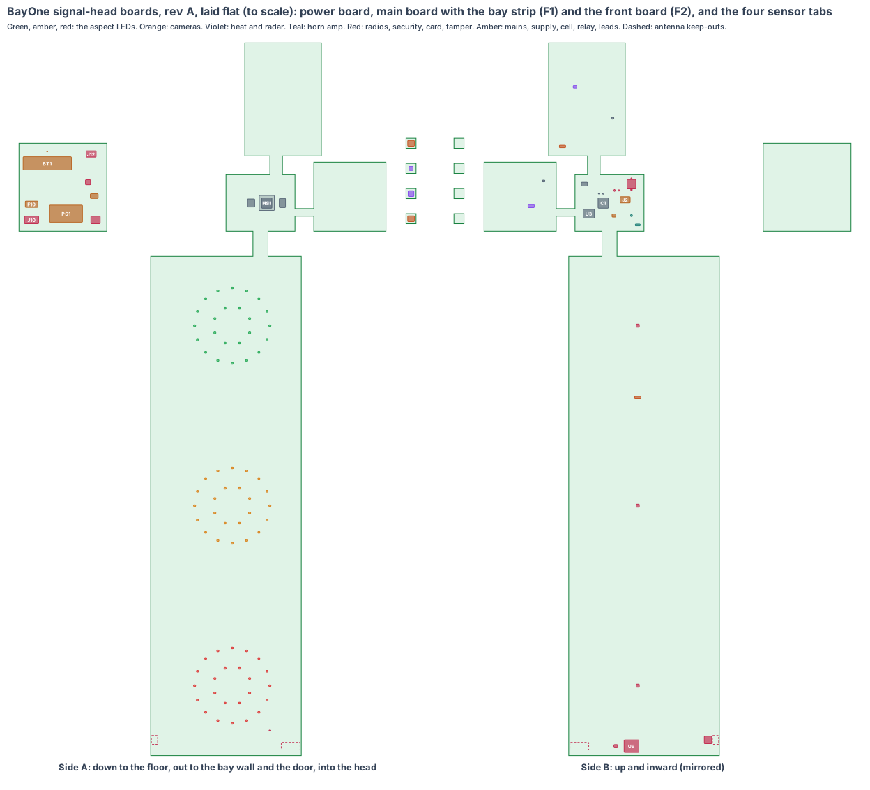
- The shape: the signal head is a 300 × 260 × 860 mm box, so the boards line its walls. An 8-layer main board (110 × 90 mm) lies flat on the head floor; a 4-layer back strip stands behind the back wall with the bay camera and heat camera tabs; a small radar strip stands behind the bay-side radome; a 4-layer front board (240 × 795 mm) stands 25 mm behind the door with the three aspects, the approach camera and the radios; a 2-layer power board on the left wall keeps mains on its own. Flexes F1, F2 and F3 join the main board to the strips and the front board; one latched lead joins the power board.
- A fix in the same run: from the bay-side wall, the pile against the near push wall lies 87° off the wall face, so no window there could show it (lesson: window). The bay and heat cameras now look out of the back wall, down the bay, 45 mm from the bay edge so the push wall top does not hide the near corner. Drawn in the CAD the same day (rev T), with the radar slot and approach window sized for our chips.
- Made from the shared rules: MEMS clocks, the latched microSD card with our software on every board, conformal coating against dust and the hall’s mist, a thermistor on the backup cell, the antennas checked for the steel hall on rev A, cameras 30 mm or more from the processor, every line of sight under 82° from its wall.
The bench signal head stays the test rig until the boards arrive.
1. The shape: five boards, four tabs
| Piece | Size | Layers | Where | What |
|---|---|---|---|---|
| Main board | 110 × 90 mm, 1.6 mm | 8 | flat on the head floor, side A 10 mm over a 3 mm aluminium spreader | the V2 core, card, security, horn amp, lead header |
| Back strip | 122 × 180 mm, 1.6 mm, on F1 (88 mm) | 4 | standing 30 mm inside the back wall | bay camera and heat camera tabs and their supplies |
| Radar strip | 115 × 110 mm, 1.6 mm, on F3 (278 mm) | 4 | standing 30 mm inside the bay-side wall | the radar tab and its supplies |
| Front board | 240 × 795 mm, 1.6 mm, on F2 (122 mm) | 4 | standing 25 mm behind the door | 3 × 24 aspect LEDs and drivers, approach camera tab, LTE-M with eSIM and antenna, Wi-Fi/BT, door tamper switch |
| Sensor tabs (4) | 16 × 16 mm, 0.8 mm, on 40 mm flex hinges | 4 | each on its sensor’s axis, the lens or chip just inside its window | IMX415 (bay, approach), MLX90640 (heat), IWRL6432AOP (radar) |
| Power board | 140 × 140 mm, 1.6 mm | 2 | on the left wall, mains behind a printed shield | mains terminal, fuse, IRM-20-5, backup cell, charger, relay and terminal |
Lead L1 (power board to main board: 5 V on two pairs, cell sense, relay drive) is about 0.4 m of 20 AWG with Molex Micro-Fit 3.0 6-pin latched ends.
2. What is on the boards
Main board, side A (down): RK3576J (U1) with a 24 × 24 heat block (HS1) to the aluminium spreader, bolted through the head floor to the 12 mm steel base plate; LPDDR4X (U2), eMMC (U11).
Main board, side B (up): decoupling field (C1), RK806S power (U3), 24 MHz and 32 kHz MEMS oscillators (Y1, Y2), ATECC608B (U8), ID chip (U9), the latched microSD (J1, reached by opening the door), MAX98357A horn amp (U31) and the pads for the speaker’s and piezo’s own wires (PD1; both stay over their floor holes), eFuse (U42), lead header (J2), factory pads (TP1).
Back strip: bay camera tab (U200, IMX415 under a 102° M12 lens, 22° down and 58° into the bay, through a 28 × 28 window) and heat camera tab (U240, MLX90640 110° × 75°, 12° down at the pile, 24 × 24 window); their supplies (U21, U23) and an ESD array (U25) on side B.
Radar strip: radar tab (U250, IWRL6432AOP, 40° down toward the bay mouth behind the 54 × 24 radome); supplies (U24) and ESD (U27).
Front board, side A (to the door): 24 LEDs behind each aspect (DG, DA, DR), the approach camera tab (U260, IMX415, 15° down to the yard, 24 × 24 window) between the green and amber aspects, the door tamper Hall switch (U7). Side B: three aspect drivers (U70–U72), the AP6275S (U5) with its antenna keep-out (ANT1) in the top-left corner, the BG95-M3 (U6) with its eSIM (U6S) and chip antenna (ANT2) in the top-right corner, both behind the door’s solid polycarbonate outside every aspect, and the approach camera supplies (U26).
Power board (side A into the head): spring-clamp mains terminal (J10), fuse and varistor (F10), IRM-20-5 (PS1), the 18650 holder and cell (BT1) with its thermistor (RT1), the charger (U50), the G5V-1 relay (K1) and its spring-clamp terminal (J11) for the site’s listed fire-panel monitor module, the lead header (J12).
3. Every connection, checked
| Link | How | Checked against |
|---|---|---|
| Camera chips to RK3576J | 4-lane MIPI CSI-2 each, over F1 or F2 and the tab hinges | IMX415 data sheet: 891 Mbps per lane; at 10 fps each uses 0.83 Gbps of 3.56 |
| Heat chip | I²C at 3.3 V over F1 | Melexis MLX90640 data sheet |
| Radar chip | SPI and a frame interrupt over F3 | TI IWRL6432AOP data sheet |
| Aspect LEDs | PWM to three constant-current drivers on the front board; open-LED detect back to the RK3576J | driver data sheet (to choose) |
| LTE-M | USB 2.0 and UART over F2; eSIM soldered | Quectel BG95 hardware design |
| Wi-Fi/BT | SDIO and UART over F2 | AMPAK AP6275S (RK3576 SDK default) |
| Power in | the head’s own mains feed, fused, into the class II IRM-20-5; 5 V on L1 into an eFuse at 3.5 A; L1 drops 0.03 V at 2 A | Mean Well IRM-20 data sheet |
| Fire panel | dry relay contact on a spring-clamp terminal to the site’s listed monitor module | Omron G5V-1 data sheet |
| Card | SD bus to the RK3576J, latched socket | Amphenol 101-00660 family drawing |
Every mating pair is checked against the makers’ documents, never “same as” another board.
4. Heat
About 3.5 W from the RK3576J goes through the heat block into the aluminium spreader and the steel base plate on the concrete wall (7 K/W est.), so the chip sits near 70 °C with the head at 45 °C inside in a summer hall. The camera and heat chips are 149 mm or more from the processor.
5. Power budget (est.)
| State | Draw |
|---|---|
| Tipping: two cameras at 10 fps, radar, heat chip, load model, LTE-M | 5.3 W |
| A call: one aspect flashing at full, the horn, the cell charging | up to 10 W, 50 % of the 20 W supply |
| Watching overnight: heat chip 2 Hz, a bay frame every 10 s, radar | 3.0 W |
| Power cut: RK3576J asleep, wakes every 60 s to read the heat chip and send over LTE-M | 0.4 W, about 26 h on the cell |
6. Factory test (every board, every time)
Spring-pin fixture on TP1 and the strips’ pads: 5 V in, the eFuse trip at 3.5 A, every rail, boot from the card, a frame of a test chart from each camera, a hot plate seen by the heat chip, a corner reflector seen by the radar, all 72 aspect LEDs and the open-LED detect, the horn amp into a test speaker, the tamper switch with a magnet, the security chip’s key, the LTE-M and BLE links; on the power board, the supply under load, the charger’s temperature cut-off with the thermistor warmed, the relay contact. Each board gets its serial number in the ID chip.
7. Who makes what
One maker makes the rigid-flex piece and the power board, assembles them (turnkey) and makes lead L1 to length. We supply the microSD cards with our software and the lenses focused at 8 m (est.). The quote pack is /build/bayone-quote.
8. Cost per signal head, electronics (est.)
| Item | Cost |
|---|---|
| V2 core (RK3576J, 4 GB LPDDR4X, 32 GB eMMC, power, AP6275S) | $48 |
| Two IMX415 camera chips, holders and lenses | $28 |
| MLX90640 heat chip | $45 |
| IWRL6432AOP radar chip | $12 |
| BG95-M3 LTE-M, eSIM and antenna | $18 |
| 72 aspect LEDs and three drivers | $10 |
| IRM-20-5, terminals, fuse, cell, charger, relay | $22 |
| Security, ID, amp, socket, Hall switch, passives | $8 |
| Boards (8-layer rigid-flex with an 800 mm front board, four tabs, a 2-layer power board), 1,000 heads | $40 |
| Lead L1 | $2 |
| Assembly and test | $15 |
| microSD card with our software | $4 |
| Total | about $252 per signal head (est.) |
The bench head’s bought boards cost about $390 at qty 1 (Pi 5, two cameras, MLX90640 board, radar module, LED sticks, Walter, supply, backup and small boards), so our boards are about $138 cheaper per head at 1,000 (est.).
9. Timeline
| Step | When |
|---|---|
| Shape and placement (this page) | done, 4 Nov 2026 |
| Rev T CAD: the boards in the signal-head CAD, every part checked in 3D; the bay and heat windows already moved to the back wall | next |
| Schematic, footprints, routing | Dec 2026 – Jan 2027 |
| Rev A boards made and tested | Mar 2027 (est.) |
10. Still to check
- The rev T CAD changes still to draw: the aluminium spreader and its bolts, the tab brackets, the door magnet boss, the printed mains shield.
- The heat chip’s reach: a 1 m hot patch at the back wall fills about one pixel; growth over minutes is the call, measured with a hot plate at 15 m on rev A.
- LTE-M from inside a steel-framed hall, with the antenna at the top of the head.
- Each aspect’s brightness and even fill through the real lens, against a plain site signal head.
- The front board’s 800 mm length and the F1 and F2 camera-lane impedance with the maker.
Sources
- Rockchip RK3576 brief: https://www.rock-chips.com/a/en/products/RK35_Series/2024/0524/1977.html
- Sony IMX415 (8.46 MP, 4-lane MIPI): https://www.sony-semicon.com/en/products/is/security/security.html
- Melexis MLX90640: https://www.melexis.com/en/product/MLX90640/Far-Infrared-Thermal-Sensor-Array
- TI IWRL6432AOP: https://www.ti.com/product/IWRL6432AOP
- Quectel BG95-M3: https://www.quectel.com/product/lpwa-bg95-m3/
- AMPAK AP6275S: https://www.ampak.com.tw/
- Mean Well IRM-20: https://www.meanwell.com/Upload/PDF/IRM-20/IRM-20-SPEC.PDF
- Omron G5V-1: https://omronfs.omron.com/en_US/ecb/products/pdf/en-g5v_1.pdf
- Microchip ATECC608B: https://www.microchip.com/en-us/product/atecc608b
- TI DRV5032: https://www.ti.com/product/DRV5032
- Samsung INR18650-35E: https://www.samsungsdi.com/
- The signal head: products/bayone/cad/bayone-cad.mjs (rev A, windows rev T); the boards: products/bayone/hardware/pcb/bayone-board.mjs
Design review (4 Nov 2026)
Every board is checked by the same rules (products/_shared/board-rules.mjs), one for each lesson any of our boards has taught us. BayOne’s boards were made with every rule from the start: 17 pass, 4 fixed, 12 to prove, 0 fail. The full review, with every number and its source, is on the board page. It shows:
- Camera pixels: a gas bottle at the far side of the tip (12 m) fills about 45 px against a 20 px need; a fleet-number digit on a reversing truck (5.6 m) about 30 px against 15; both 8 MP chips at 10 fps use 23 % of their links and 166 Mpx/s of the image processor’s 480.
- Every bay call in view: the fresh load, a battery at the front, the far side of the tip, the 4 m line and smoke; the pile middle, both corners and a hot item; the bay mouth behind the truck, the loader area and the far side; the fleet number, the next truck and a person in the lane, from where each lens or chip really sits in its wall.
- The bay and heat cameras look out of the back wall (fixed): from the bay-side wall the pile against the near push wall lies 87° off the face (lesson: window); the back wall faces down the bay. The radar slot and approach window were also sized for our chips (fixed). Drawn in the CAD the same day.
- The latched microSD (J1) is fitted, and our software starts from it; updates run only when the bay is closed.
- A thermistor on the backup cell holds charging outside 0 to 45 °C, and conformal coating against dust and mist is asked for in the quote.
- Fast lines on a solid ground plane (to prove, lesson: planes, from the CricketOne test-board layout of 4 Nov 2026): RK3576J memory; 2 camera MIPI links (100 Ω pairs); USB (90 Ω); antenna feed (50 Ω, keep-out on every layer); card lines (length-matched, no vias under the socket). Ground on the layer next to the parts (inner layer 1, supply on inner layer 2; the whole bottom of a 2-layer section), one via beside each ground and supply pad and none in pads, no copper or vias in the antenna keep-out on any layer or under the card socket, the impedance lines routed first with a test coupon. The quote asks for it; the routed board’s design rule check proves it.
- To prove on rev A: the heat chip’s reach at the back wall (about 1 px for a 1 m patch), the AI time, the power-cut run on the cell, LTE-M in a steel hall, the tab brackets, the aspects’ brightness, mains creepage, the flexes, the tamper magnet and the boards in the rev T CAD.
The request for quote is /build/bayone-quote.