DockOne: one circuit board of our own in each guard
DockOne is the pair of steel door-track guards at a dock door. Each guard gets one rigid-flex board of our own in its sealed top bay, with every chip soldered on it: no computer boards, camera cables, plugs or adapters inside. The only cable is the lead between the two guards, which a pair either side of a 2.7 m door cannot avoid; it is latched and keyed at both ends.
Board code: products/dockone/hardware/pcb/dockone-board.mjs (shape, every part, every check), board-3d.mjs (the 3D model on the page), board-review.mjs (the design review with the shared rules). Numbers marked est. are estimates until rev A.
1. The shape: three pieces in each guard
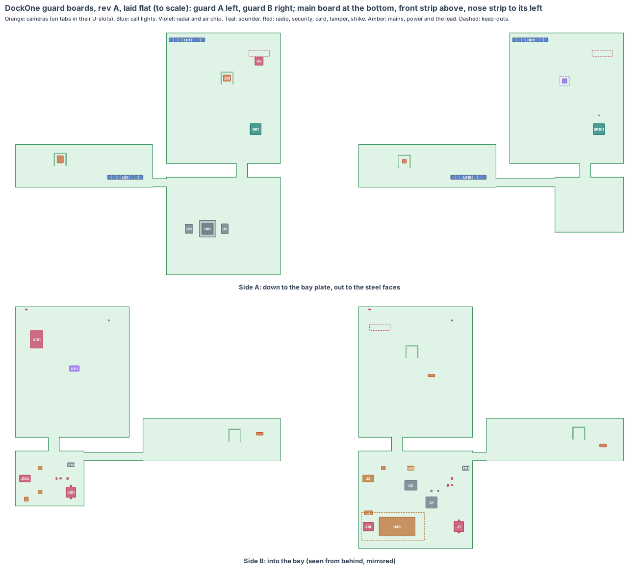
Each guard’s top bay has two spaces (cad/dockone-cad.mjs): the main bay over the 5 mm steel bay plate (inside x 1,466 to 1,640, y 5 to 198, z 995 to 1,226 under the cap) and the nose cavity beside the door-track notch (x 1,376 to 1,471, y 135 to 198). Each board is one piece:
| Piece | Guard A | Guard B |
|---|---|---|
| Main board, flat on stand-offs over the bay plate | 8 layers, 166 × 142 mm, 12 mm up: RK3576J (side A, heat block down to the bay plate), memory, eMMC; side B: the mains supply, its terminal and fuse, the lead header, security and ID chips, strike sensor, microSD | 4 layers, 100 × 80 mm, 8 mm up: microSD, lead header, 5 V eFuse, RS-485, 3.3 V buck, security and ID chips, strike sensor |
| Front strip, standing behind the front face (into the building) | 166 × 190 mm, 24 mm behind the face: 8 call-light LEDs and a light bar behind the front slot, sounder behind the tone holes, Wi-Fi 6/BT module behind the new antenna window, the dock camera on its tab, Hall tamper switch at the top edge | 166 × 190 mm, 4 mm behind the face: the ESP32-S3 module behind the antenna window, the IWRL6432AOP radar chip behind the 50 × 20 window, SHT45 behind the vents, 8 call-light LEDs, sounder, Hall tamper switch |
| Nose strip, standing behind the nose face (into the doorway) | 62 × 200 mm, 24 mm behind the face: 8 call-light LEDs behind the nose slot, the door camera on its tab | 62 × 200 mm, 15 mm behind the face: 8 call-light LEDs, the OV2640 door camera on its tab |
| Flexes | F1 folds the front strip up from the main board’s front edge (55 mm); F2 runs from the main board’s left edge across and up to the nose strip (86 mm) | F1 79 mm, F2 165 mm |
Camera tabs. Each camera chip sits on a 16 × 16 mm tab cut from its strip in a U-slot, on a 25 mm flex hinge, held on the camera’s axis by a printed bracket on the guard wall. The lens barrel passes through the hole in the steel to just inside the face, behind a flush clear cover.
2. What is on the boards
- Brain (guard A): Rockchip RK3576J, industrial grade (−40 to 85 °C), 6 TOPS NPU, 16 MP image processor; 4 GB LPDDR4X; 32 GB eMMC; RK806S-5 power chip; MEMS clocks.
- Cameras: door camera A and dock camera A are Sony IMX415 8 MP chips (C1) on 4-lane MIPI; door camera B is an OmniVision OV2640 2 MP chip on the ESP32-S3’s camera port, the second view for stereo.
- Guard B core (S1): Espressif ESP32-S3-WROOM-1-N16R8, soldered by its edge pads; TI IWRL6432AOP 60 GHz radar with its rails, MEMS clock and flash; Sensirion SHT45.
- Both guards: 16 call-light LEDs (8 in the nose, 8 in the front face), a magnetic sounder, an LSM6DSOX strike sensor, an ATECC608B security chip, an ID chip, a latched microSD card with our software, a DRV5032 Hall tamper switch under a magnet in the cap.
3. Every connection, checked
| Connection | What | Check |
|---|---|---|
| Mains in | WAGO 2604-3103 push-in terminal (L, N, earth to the guard) on guard A, wires clamped, no plug, behind a conduit entry in the outer side face (rev T) | 450 V rated; the earth goes to the steel guard; fuse and surge part before the supply |
| Mains supply | Mean Well IRM-20-5, PCB-mount, encapsulated, class II | soldered on the main board; 6.4 mm creepage with a routed slot round its mains pins |
| Lead A to B | Molex Micro-Fit 3.0 43045-0802 8-pin vertical header on each main board, positive latch, keyed; 5 V ×2, GND ×3, RS-485 A/B, frame sync | same pin-out both ends, checked in the board code; mating housing 43025-0800 with crimp terminals; 18 AWG for power |
| Cameras | the camera chips on their own tabs, joined by the board’s own flex | no camera cable; MIPI lanes impedance-controlled through F1/F2 |
| Card | Amphenol 101-00660 class hinged, latched microSD lid | a push-push socket would eject on a forklift strike |
4. Heat
The RK3576J (about 3.5 W working, est.) sits on side A of guard A’s main board, 12 mm over the 5 mm steel bay plate, with a 24 × 24 aluminium block and gap pads between: the steel guard is the heat sink. At 45 °C in the guard top (a summer dock with the doors open, est.) the chip runs at about 63 °C (5 K/W, est.). The camera chips are on their own tabs, 186 to 228 mm from the brain.
5. Power budget (est.)
| State | Guard A | Guard B | Total |
|---|---|---|---|
| Door shut, after-hours watch | 2.0 W | 0.6 W | 2.6 W |
| Working: 5 fps door, 2 fps dock, radar 10 Hz | 4.5 W | 1.0 W | 5.5 W |
| A call: all call lights at full and both sounders | 8.5 W | 2.5 W | 11 W |
The IRM-20-5 gives 20 W, so the peak is 55 % of it. Guard B’s 0.6 A peak drops 0.11 V over about 9 m of 18 AWG in the header conduit. No cells: when the door circuit is off, the dock door is not working either.
6. Factory test (every board, every time)
Spring-pin fixture on the factory pads: current-limited first power-on (a short is found in about 1 s), rails, the RK3576J or ESP32-S3 boots our test image from the card, both cameras stream a test chart, the radar sees a corner reflector, the strike sensor and SHT45 read, every call light and sounder runs, the Hall switch sees a test magnet, the lead loops RS-485 and sync between a guard A and a guard B board, the security chip gets its key, the ID chip its serial. Mains is tested on guard A with an isolating transformer and a hi-pot test.
7. Who makes what
The boards, their assembly and test: a rigid-flex maker with fine-pitch ball-grid assembly (the same makers as our other boards). The guards, cap and brackets: our CAD, steel by a fabricator. The supply, lead and terminal: bought and fitted by the board maker.
8. Cost per door, electronics (est.)
| Item | qty 10 | qty 1,000 |
|---|---|---|
| Guard A board (V2 core, two C1 cameras, mains supply) | $190 | $95 |
| Guard B board (S1 core, OV2640, radar) | $70 | $32 |
| Lead, terminal, covers, magnets | $25 | $12 |
| Per door | $285 | $139 |
9. Timeline
Shape and placement now (rev A-0). Schematic and footprints next, from Rockchip’s RK3576 and Espressif’s ESP32-S3 reference designs; the rev T CAD draws the bigger camera holes, the antenna windows, the brackets and the cap magnet pocket; rev A boards with our other boards in early 2027.
10. Still to check
- The RK3576J package outline, ball map and thermal figures from Rockchip’s datasheet (sizes are est.).
- The IMX415 lenses: a 60° portrait M12 lens for the door, a 70° M12 for the dock, a 60° M7 for guard B, each with a barrel long enough to reach the face.
- Radio range from behind the 60 × 10 antenna windows in steel guards, at a real dock (rev A).
- The PAS 13 strike test with the boards running and logging.
- Mains safety at a test lab (IEC/UL 62368-1), with the earth to the guard.
- The window heater for freezer docks (on the bench design, about 2 W): its driver and pads go on the strips in rev T.
Sources
- Rockchip RK3576 product brief: https://www.rock-chips.com/a/en/products/RK35_Series/2024/0328/1975.html
- Mean Well IRM-20 datasheet: https://www.meanwell.com/Upload/PDF/IRM-20/IRM-20-SPEC.PDF
- Molex Micro-Fit 3.0 connectors: https://www.molex.com/en-us/products/connectors/wire-to-board-connectors/micro-fit-connectors
- WAGO 2604 PCB terminal blocks: https://www.wago.com/global/pcb-terminal-blocks-and-pluggable-connectors
- Sony IMX415: https://www.sony-semicon.com/en/products/is/security/security.html
- TI IWRL6432AOP: https://www.ti.com/product/IWRL6432AOP
- TI DRV5032: https://www.ti.com/product/DRV5032
- Espressif ESP32-S3-WROOM-1 datasheet: https://www.espressif.com/sites/default/files/documentation/esp32-s3-wroom-1_wroom-1u_datasheet_en.pdf
- PAS 13:2017 barrier impact tests (BSI): https://knowledge.bsigroup.com/products/code-of-practice-for-safety-barriers-used-in-traffic-management-within-workplace-environments-with-test-methods-for-safety-barrier-impact-resilience
- IEC 62368-1: https://webstore.iec.ch/en/publication/27412
Design review (4 Nov 2026)
The review uses the rules every one of our boards shares (products/_shared/board-rules.mjs) and is shown on the board page. Result: 0 fail; 1 fixed; the rest pass or are proved on rev A.
- Fixed (new lesson “window”): the bench cameras sat behind Ø20 holes turned 35° and 30° from the steel face, so most of their view was the inside of the guard. A first try with a 100° lens needed a hole wider than the guard. Now each lens is chosen from its calls (door 60° portrait, dock 70°), the door chips are turned on their side, and the lens barrel passes through the wall to just inside the face: every call’s line of sight is within 67° of the face, and the holes become Ø44 (guard A nose), Ø28 (guard B nose) and Ø40 (dock), with flush clear covers. The rev T CAD draws them.
- New in the shared tools: the RK3576 (V2 core) in board-rules.mjs, and board-quote.mjs now names the board’s own Rockchip core in the scope, so V2 boards get the right quote.
- Fast lines on a solid ground plane (to prove, lesson: planes, from the CricketOne test-board layout of 4 Nov 2026): RK3576J memory; 3 camera MIPI links (100 Ω pairs); USB (90 Ω); antenna feed (50 Ω, keep-out on every layer); card lines (length-matched, no vias under the socket). Ground on the layer next to the parts (inner layer 1, supply on inner layer 2; the whole bottom of a 2-layer section), one via beside each ground and supply pad and none in pads, no copper or vias in the antenna keep-out on any layer or under the card socket, the impedance lines routed first with a test coupon. The quote asks for it; the routed board’s design rule check proves it.
- To prove on rev A: AI time on the NPU, power-cut log, radio range from behind the antenna windows, the camera brackets in the rev T CAD, mains safety, the cap tamper switch point, the PAS 13 strike, the flex lengths.
New shared rule (4 Nov 2026, from PumpOne): antennas outside metal boxes. A radio inside a closed metal enclosure now fails the review unless its antenna is outside the metal. This board’s antennas already use the 60 × 10 PC antenna window in each guard’s front face, so the check passes and the review names the window (lesson: enclosure).