ClassOne: circuit boards of our own
What changed (4 Nov 2026). The rev A bench whiteboard is built from bought boards joined by leads: a Raspberry Pi 5, two Camera Module 3 Wide boards on ribbons, an SPH0645 mic board, 12 NeoPixel sticks, a MAX98357A amp board, an ATECC608 board, an SCD30 CO2 module up the side frame and a PN532 board in the pen tray. ClassOne now gets boards of our own, like CricketOne, DockOne and StudyOne, with every chip placed straight onto them, made with every shared design-review rule from the start.
- The chips: the V2 core (Rockchip RK3576J, 2 GB LPDDR4X, 16 GB eMMC, AMPAK AP6275S Wi-Fi 6/BT module), two bare Sony IMX415 8 MP camera chips under M12 lens holders (the C1 camera on the board), 96 RGB LEDs for the time bar, an Infineon IM69D130 MEMS mic, the MAX98357A speaker amp, the security chip, Hall tamper switches, a Sensirion SCD43 CO2 chip and an NXP PN7160 NFC chip with a printed coil.
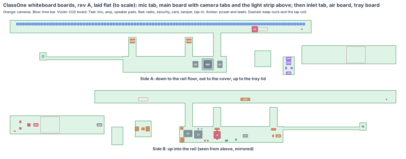
- The shape: the whiteboard’s electronics live in four places, so the boards do too. In the header rail, one rigid-flex piece: an 8-layer main board (220 × 34 mm) flat on the rail floor behind the camera windows; two 16 × 16 mm camera tabs on 25 mm flex hinges off its front edge, each held on its camera’s axis by a printed bracket; a 4-layer light strip (640 × 27 mm) standing 4 mm behind the opal cover on a 16 mm flex; a small mic tab on a tail over the rail’s mic port. At the rail’s right end, an inlet tab with the USB-C power inlet. In the left side frame’s pocket, 4.5 ft up, an air board with the CO2 chip. Under the pen tray’s lid, a tray board where pupils tap in.
- Why more than one board: the CO2 chip must sit 3 to 6 ft up (California PUC 1625) and the tap-in at a child’s reach, 1.2 m below the header; no board can span that. The air and tray boards hang on one latched, keyed bus (differential I²C) in the side frame’s cable channel, like the lead between DockOne’s two guards. The inlet is at the rail’s end, beside the wall socket.
- Only 5 V in the board. Power comes from a listed USB-C adapter (5 V 3 A) at the wall socket beside the board. No cells: a classroom has power whenever school is open.
- Made from the shared rules: MEMS clocks, the latched microSD card with our software on every board, conformal coating against daily board wipes, the antenna checked for the aluminium rail on rev A, cameras 30 mm or more from the processor, the lens chosen from the calls and its front just inside the cover (lesson: window).
The bench whiteboard stays the test rig until the boards arrive.
1. The shape: six boards, one bus
| Piece | Size | Layers | Where | What |
|---|---|---|---|---|
| Main board | 220 × 34 mm, 1.6 mm | 8 | flat in the header rail, side A 10 mm over the aluminium rail floor | the V2 core, card, security, amp, camera supplies, power and bus headers |
| Camera tabs (2) | 16 × 16 mm, 0.8 mm, on 25 mm flex hinges | 8 | off the main board’s front edge at x ±60, turned 30° out and 20° down | IMX415 and M12 lens holder each, lens front 0.5 mm inside the cover’s face |
| Light strip | 640 × 27 mm, 1.6 mm | 4 | standing 4 mm behind the opal cover, above the camera windows, on a 16 mm flex (F1, 61 mm) | 96 time-bar LEDs, Wi-Fi/BT module, cover tamper switch |
| Mic tab | 14 × 16 mm, 0.8 mm, on a 6 mm tail (163 mm) | 2 | on the rail floor over the mic port at x −250 | IM69D130 mic and its gasket |
| Inlet tab | 34 × 34 mm, 1.6 mm | 4 | at the rail’s right end, the USB-C mouth in the end-wall hole | USB-C inlet, eFuse, latched power header |
| Air board | 24 × 38 mm, 1.6 mm | 2 | standing in the CO2 pocket in the left side frame, 1,362 to 1,400 mm up | SCD43 CO2 chip, bus buffer, 3.3 V, two latched bus headers |
| Tray board | 200 × 39 mm, 1.6 mm | 4 | flat 3 mm under the tray lid in the NFC compartment | PN7160 NFC chip and printed coil, bus buffer, 3.3 V, tray tamper switch |
Leads: L1 (inlet tab to main board, 5 V, about 1.1 m of 18 AWG, Molex Micro-Fit 3.0 2-pin latched); L2 (main board to air board, about 1.8 m) and L3 (air board to tray board, about 0.7 m), both 26 AWG with JST GH 6-pin latched ends, in the side frame’s channel.
2. What is on the boards
Main board, side A (down, to the rail floor): RK3576J (U1) with a 24 × 24 aluminium heat block and gap pads to the rail floor (HS1), LPDDR4X (U2), eMMC (U11).
Main board, side B (up): the RK3576J decoupling field (C1), RK806S power (U3), 24 MHz and 32 kHz MEMS oscillators (Y1, Y2), ATECC608B (U8) and the ID chip (U9), the latched microSD socket (J1), reached by taking off the header cover, the eFuse (U42), the latched power header (J2) and bus header (J3), the PCA9615 bus buffer (U43), the MAX98357A amp (U31) and the speaker wire pads (PD1, the 28 mm speaker stays over the floor grille), the two cameras’ supplies (U21, U22), factory pads (TP1).
Camera tabs: an IMX415 (U200, U210) under an M12 lens holder with a 102° × 69.6° lens (LH1, LH2) on each, turned 30° out and 20° down; head counts only, never faces.
Light strip, side A (to the cover): 96 WS2812B-class LEDs at 6.4 mm pitch (D1–D96: the time bar running green to amber to red, group colours, register and air calls), the AP6275S Wi-Fi/BT module (U5) with its antenna keep-out (ANT1) behind the opal, the DRV5032 cover tamper switch (U7) under a magnet in the cover. Side B: the level shifter (U36) and the time bar’s power and 1 A limit (U37).
Mic tab: IM69D130 (MK1) over a hole through the tab, the gasket (GK1) to the rail’s mic port.
Inlet tab: the USB-C power-only receptacle (J4) in the end-wall hole, the eFuse and TVS (U40), the latched power header (J5).
Air board: Sensirion SCD43 (U50) behind the vent slots, the PCA9615 (U51), a 3.3 V LDO (U52), the two bus headers (J50, J51).
Tray board: the printed 40 × 35 mm coil (ANT2) on side A under the tap-here mark; PN7160 (U60), its matching network (U61), the PCA9615 (U62, end of the bus), a 3.3 V LDO (U63), the bus header (J60) and the DRV5032 tray-lid tamper switch (U64) on side B.
3. Every connection, checked
| Link | How | Checked against |
|---|---|---|
| Camera chips to RK3576J | 4-lane MIPI CSI-2 each, across the 25 mm flex hinges | IMX415 data sheet: 891 Mbps per lane; at 1 fps each uses 0.08 Gbps of 3.56 |
| Time bar | one data line up F1, 3.3 → 5 V level shifter | WS2812B data sheet |
| Wi-Fi/BT | SDIO and UART up F1 | AMPAK AP6275S (RK3576 SDK default) |
| Mic | PDM along the mic tail | Infineon IM69D130 data sheet |
| Speaker amp | I2S on the main board, the speaker’s own wires to the pads | MAX98357A data sheet |
| CO2 and tap-in | I²C through PCA9615 differential buffers over L2 and L3 (about 2.5 m in all) | NXP PCA9615 data sheet (est. 3 m at 400 kHz, to read); PN7160 and SCD43 on I²C |
| Power in | USB-C, 5.1 kΩ CC pull-downs, 5 V up to 3 A, eFuse at 3.5 A; L1 drops 0.1 V at 2.1 A | USB Type-C spec 2.x (power-only sink); the adapter is listed |
| Card | SD bus to the RK3576J, latched socket | Amphenol 101-00660 family drawing |
Every mating pair is checked against the makers’ documents, never “same as” another board.
4. Heat
The 2.4 m aluminium header rail is the heat sink: about 3 W from the RK3576J goes through the heat block into the rail floor (4 K/W est.), so the chip sits near 52 °C with the rail at 40 °C inside near a warm ceiling. The camera chips are 61 mm and 157 mm from the processor.
5. Power budget (est.)
| State | Draw |
|---|---|
| Counting every 10 s (RK3576J, two cameras at 1 fps, Wi-Fi) | 4.1 W |
| CO2, tap-in, mic, security | 0.4 W |
| Time bar (1 A limit, firmware caps the brightness) | up to 4 W |
| Speaker peak (a chime or a group call) | 1.5 W |
| Peak | 10.5 W, 70 % of the 15 W adapter |
| Night: CO2 and tamper only, processor asleep | 0.6 W |
6. Factory test (every board, every time)
Spring-pin fixture on TP1 and the small boards’ pads: 5 V in through the USB-C, the eFuse trip at 3.5 A, every rail, boot from the card, a frame of a test chart from each camera, all 96 LEDs, the mic against a 1 kHz tone, the amp into a test speaker, the CO2 chip against fresh air (about 420 ppm), a test card read through a 3 mm lid, both tamper switches with a magnet, the security chip’s key, the Wi-Fi link. Each board gets its serial number in the ID chip.
7. Who makes what
One maker makes the rigid-flex piece and the three small boards and assembles them (turnkey), and makes the three leads to length. We supply the microSD cards with our software and the lenses focused at 4 m (est.). The quote pack is /build/classone-quote.
8. Cost per whiteboard, electronics (est.)
| Item | Cost |
|---|---|
| V2 core (RK3576J, LPDDR4X, eMMC, power, AP6275S) | $42 |
| Two IMX415 camera chips, holders and lenses | $28 |
| SCD43 CO2 chip | $20 |
| PN7160, coil match, mic, amp, security, ID, buffers | $10 |
| 96 LEDs and their power | $8 |
| USB-C, eFuses, socket, Hall switches, passives | $6 |
| Boards (8-layer rigid-flex with a 640 mm strip, three small boards), 1,000 whiteboards | $30 |
| Three leads | $5 |
| Assembly and test | $12 |
| microSD card with our software | $4 |
| Total | about $165 per whiteboard (est.) |
The bench whiteboard’s bought boards cost about $300 at qty 1 (Pi 5, two cameras, SCD30, PN532, 12 LED sticks and the small boards), so our boards are about $135 cheaper per whiteboard at 1,000 (est.).
9. Timeline
| Step | When |
|---|---|
| Shape and placement (this page) | done, 4 Nov 2026 |
| Rev T CAD: the boards in the whiteboard CAD, every part checked in 3D; the camera windows already opened outward | next |
| Schematic, footprints, routing | Dec 2026 – Jan 2027 |
| Rev A boards made and tested | Mar 2027 (est.) |
10. Still to check
- The rev T CAD changes still to draw: the camera brackets on the rail floor, magnet pockets in the header cover and the tray lid, the side frame’s cable channel from the rail to the pocket and on to the tray.
- The SCD43’s accuracy from Sensirion’s data sheet against California’s ±75 ppm at 1,000 ppm (est. ±(30 ppm + 3 %)), and a reference-meter check on rev A.
- The PN7160 coil tuned with the 3 mm lid and the aluminium tray round it.
- Wi-Fi range from inside the aluminium rail (antenna behind the opal).
- The 640 mm light strip’s panel length and the F1 SDIO impedance with the maker.
Sources
- Rockchip RK3576 brief: https://www.rock-chips.com/a/en/products/RK35_Series/2024/0524/1977.html
- Sony IMX415 (8.46 MP, 4-lane MIPI): https://www.sony-semicon.com/en/products/is/security/security.html
- AMPAK AP6275S: https://www.ampak.com.tw/
- Sensirion SCD4x CO2 sensors: https://sensirion.com/products/catalog/SCD43
- NXP PN7160: https://www.nxp.com/products/PN7160
- NXP PCA9615 differential I²C buffer: https://www.nxp.com/products/PCA9615
- Infineon IM69D130: https://www.infineon.com/cms/en/product/sensor/mems-microphones/mems-microphones-for-consumer/im69d130/
- Analog Devices MAX98357A: https://www.analog.com/en/products/max98357a.html
- Microchip ATECC608B: https://www.microchip.com/en-us/product/atecc608b
- TI DRV5032: https://www.ti.com/product/DRV5032
- California PUC 1625 (CO2 monitors in classrooms): https://www.cpuc.ca.gov/
- The whiteboard: products/classone/cad/classone-cad.mjs (rev A, camera windows rev T); the boards: products/classone/hardware/pcb/classone-board.mjs
Design review (4 Nov 2026)
Every board is checked by the same rules (products/_shared/board-rules.mjs), one for each lesson any of our boards has taught us. ClassOne’s boards were made with every rule from the start: 16 pass, 3 fixed, 12 to prove, 0 fail. The full review, with every number and its source, is on the board page. It shows:
- Room camera pixels: a pupil’s head at the back seat (7.6 m) fills about 43 px against a 20 px need; at one frame a second each 8 MP chip uses 2 % of its link, and both together 17 Mpx/s of the image processor’s 480.
- Every room call in view: front and back desks on both sides, the centre, the back corners, the reading-group table and the door, from where each lens really sits in the cover.
- The camera windows open outward (fixed): the line of sight to a door at the front corner runs 80° from the cover, so the far side of the lens rim needs room; both windows grow from 30 × 30 to 63 × 34, opening outward, because the door can be on either side of a real classroom (lesson: window). Drawn in the CAD the same day.
- The latched microSD (J1) is fitted, and our software starts from it; updates run only after school hours.
- Conformal coating against board wipes and spray is asked for in the quote.
- Fast lines on a solid ground plane (to prove, lesson: planes, from the CricketOne test-board layout of 4 Nov 2026): RK3576J memory; 2 camera MIPI links (100 Ω pairs); USB (90 Ω); antenna feed (50 Ω, keep-out on every layer); card lines (length-matched, no vias under the socket). Ground on the layer next to the parts (inner layer 1, supply on inner layer 2; the whole bottom of a 2-layer section), one via beside each ground and supply pad and none in pads, no copper or vias in the antenna keep-out on any layer or under the card socket, the impedance lines routed first with a test coupon. The quote asks for it; the routed board’s design rule check proves it.
- To prove on rev A: the AI time per count, Wi-Fi from inside the rail, the camera brackets, the time bar through the opal, the CO2 chip’s accuracy, the tap-in read range, the tamper magnets, the flexes, and the boards in the rev T CAD.
The request for quote is /build/classone-quote.