FarmOne: one circuit board of our own
What changed (4 Nov 2026). The rev A bench trough is built from bought boards joined by leads: a Raspberry Pi Zero 2 W, two Camera Module 3 Wide boards on ribbons, two MLX90640 boards, a Walter LTE-M board, a Pololu VL53L1X board, an SHT45 board, a MAX9814 mic board, two NeoPixel sticks, an ATECC608 board, a PowerBoost charger, a 5 V regulator and four loose cells. FarmOne now gets one circuit board of our own, like CricketOne, PoolOne and ClassOne, with every chip placed straight onto it, made with every shared design-review rule from the start.
- The chips: the V1 core (Rockchip RV1126B, 1 GB LPDDR4X, 8 GB eMMC), two bare Sony IMX415 8 MP camera chips under M12 lens holders (the C1 camera on the board, one for each paddock), two Melexis MLX90640 heat-camera chips, an Espressif ESP32-S3-WROOM-1 module (S1) that stays awake while the RV1126B sleeps, a Quectel BG95-M3 LTE-M modem with GNSS and a soldered MFF2 eSIM, an ST VL53L1X float-height chip, a Sensirion SHT45 air chip, an Infineon IM69D130 mic, 16 call-light LEDs, a sounder, the security chip, the tamper switch, a TI BQ25798-class solar charger and four Keystone 1042 cell holders with a thermistor.
- Why S1 is added to V1 + C1: the trough runs on a 6 W panel. The RV1126B with a camera draws about 1.6 W, so it runs only while stock are at the water (about 3 h a day, est.). The ESP32-S3 watches the meter, the float, the heat chips and the mic on about 0.1 W and wakes it.
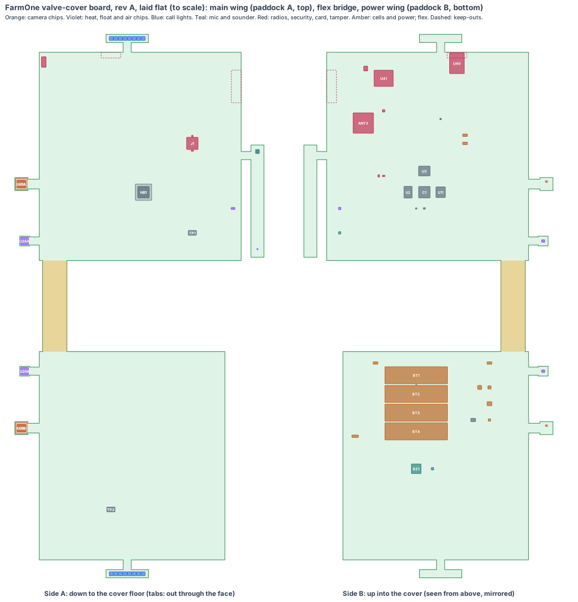
- The shape: the valve cover’s cavity is 108 mm tall over the float bay, with the water meter standing on the inlet riser in the middle. So the board goes round it: an 8-layer main wing on the paddock A side and a 4-layer power wing on the paddock B side lie flat 8 mm over the cover floor, joined by a 30 mm flex bridge on the floor between the water-side face and the inlet riser. Four small camera and heat tabs on flex arms sit behind the water-side face, each turned 30° out to its paddock and tilted down, with the lens front just inside the face. Two lamp strips sit under the call-light slots in the top, and an end strip stands against the end face with the mic and the air chip.
- No mains at the water point: the 6 W panel in the cover top charges four soldered 18650 cells through a solar charger with maximum-power tracking. Solder pads take the panel, the water meter’s pulse wires and the water probe; there are no plugs.
- Made from the shared rules: MEMS clocks, the latched microSD card with our software on every board, conformal coating against splashes and condensation, charging held outside 0–45 °C by the thermistor, each lens chosen and placed from its calls (lesson: window).
The bench trough stays the test rig until the boards arrive.
1. The shape: nine pieces on one board
| Piece | Size | Layers | Where | What |
|---|---|---|---|---|
| Main wing | 248 × 256 mm, 1.6 mm | 8 | flat in the cover, x 512 to 760, y 56 to 312, side A 8 mm over the floor | the V1 core, S1, LTE-M and GNSS, float chip, card, security, tamper |
| Flex bridge | 30 × 112 mm | 2 (flex) | flat on the floor, x 516 to 546, between the face and the inlet riser | power, the paddock B camera’s 4 lanes, I²C |
| Power wing | 228 × 256 mm, 1.6 mm | 4 | flat in the cover, x 512 to 740, y −312 to −56 | solar charger, four cells, sounder, panel, meter and probe pads |
| Camera tabs A and B | 16 × 16 mm, 1.0 mm | 4 | on flex arms (about 76 mm, est.), turned 30° out and 15° down, lens fronts 3.4 mm in along the axis at y ±148, z 901 | IMX415 under an M12 holder |
| Heat tabs A and B | 12 × 12 mm, 1.0 mm | 4 | on flex arms (about 70 mm, est.), turned 30° out and 10° down, at y ±78, z 901 | MLX90640 |
| Lamp strips A and B | 52 × 10 mm, 0.8 mm | 2 | side A up under the call-light slots (x 620, y ±400) | 8 WS2812B LEDs each |
| End strip | 138 × 16 mm, 0.8 mm | 2 | standing 2 mm from the end face, y −130 to 8 | mic over the port, air chip behind the vents |
Each tab’s pose is solved in the board code (farmone-board.mjs): the lens front is moved in along the camera’s axis until every point of the lens rim, the holder and the tab is 0.3 mm inside the water-side face.
2. What is on the board
Main wing, side A (down, to the cover floor): RV1126B (U1) with a 20 × 20 aluminium heat block and gap pads to the cover floor over the shaded float bay (HS1); the latched microSD socket (J1), reached by lifting the cover off; the VL53L1X float-height chip (U12) over the Ø10 floor window; the D2F-01 tamper switch (SW1) over the Ø4 floor hole; factory pads (TP1).
Main wing, side B (up, into the cover): the RV1126B decoupling (C1), LPDDR4X (U2), eMMC (U11), power rails (U3), 24 MHz and 32 kHz MEMS oscillators (Y1, Y2), ATECC608B (U8) and the ID chip (U9), ESP32-S3-WROOM-1 (U40) with its antenna at the +y edge (ANT1), BG95-M3 (U41) and the eSIM (U42), the LTE chip antenna at the +x edge (ANT2), the GNSS patch (ANT3) beside the solar panel with its amplifier (U43), the LED level shifter (U36), both cameras’ supplies (U21, U22), the float chip’s supply (U14), the end-strip buffers (U25).
Power wing, side B: the solar charger (U50) and its inductor (L50), the 3.3 V supply and eFuse (U51), the fuel gauge (U52), four Keystone 1042 holders (BT1–BT4) with the thermistor (RT1) between the first two, the sounder (BZ1) under the tone holes and its driver (U31), solder pads for the panel (PD1), the meter (PD2) and the probe (PD3); factory pads on side A (TP2).
Tabs and strips: IMX415 (U20A, U20B) under M12 holders (LH1A, LH1B) with their oscillators (Y20A, Y20B); MLX90640 (U24A, U24B) with their supplies (U26A, U26B); 16 call-light LEDs (DA1–DA8, DB1–DB8); the mic (MK1) with its gasket (GK1) and the SHT45 (U27).
3. Every connection, checked
| Link | How | Checked against |
|---|---|---|
| Cameras to the RV1126B | 4-lane MIPI CSI-2 each, the paddock B lanes over the bridge | IMX415 at 5 fps uses 12 % of its link |
| Heat chips | I²C at 400 kHz, read by the ESP32-S3 at 0.5 Hz, and by the RV1126B when awake | MLX90640 datasheet |
| Wake | ESP32-S3 GPIO to the RV1126B power enable and a UART | our pattern from AthleticsOne and PoolOne |
| LTE-M and GNSS | UART and power-key from the ESP32-S3; RF to the chip antenna and the patch | Quectel BG95 hardware design guide |
| Float, air, mic | I²C (VL53L1X, SHT45), PDM (mic) | maker datasheets |
| Meter | reed pulse into an ESP32-S3 counter input with debounce | DAE AS200U pulse output |
| Water probe | 1-Wire with a 4.7 k pull-up | DS18B20 |
| Call lights | one data line per strip through the level shifter | WS2812B |
| Cells | four holders in parallel, thermistor to the charger’s NTC input | Samsung INR18650-35E, BQ25798 family |
4. Heat
About 1.6 W from the RV1126B while it is awake, into the cover floor over the float bay through a 20 × 20 heat block (est. 64 °C at the chip with 45 °C on the floor in full summer sun). The cells lie on the floor too, under the shade of the solar panel (est. 50 °C); charging holds above 45 °C. The camera chips sit on tabs away from the processor.
5. Power budget (est.)
| State | Draw | Hours a day |
|---|---|---|
| Watching: ESP32-S3 awake, LTE-M asleep between reports, heat chips at 0.5 Hz, meter, float | 0.25 W | 21 |
| Stock at the water: RV1126B and one camera | 1.6 W | 3 |
| A grazing day, through the 90 % converter | about 11.2 Wh | 24 |
Four cells, aged to 80 % and at 5 °C, give about 66 hours: two days of cloud with 37 % spare. A 3 h winter sun day on the 6 W panel puts back about 18 Wh. Peak about 3.5 W (camera and LTE-M transmitting).
6. Factory test (every board, every time)
Spring pins on TP1 and TP2: rails, current at each state, boot from the card, both cameras and heat chips streaming, LTE-M registered on a test network, GNSS fix outdoors, float chip at a 100 mm target, mic and sounder loop, call lights, tamper switch, charger from a bench supply on the panel pads, thermistor read.
7. Who makes what
We design the board. A rigid-flex maker builds and assembles it from the quote pack; we load our software onto the microSD card. The cover, the trough, the water meter and the probe are bought or printed, as in DESIGN.md.
8. Cost per trough, electronics (est.)
| qty 10 | qty 1,000 | |
|---|---|---|
| Board, rigid-flex, assembled with every chip | $310 | $118 |
| Four cells | $16 | $11 |
| Water meter, probe, panel (bought, stay) | $150 | $96 |
The bench electronics cost about $360 a trough. Estimates until the quotes come back.
9. Timeline
| When | What |
|---|---|
| Nov 2026 | Shape and placement (this page) |
| Dec 2026 | Schematic and footprints |
| Jan 2027 | Routing, files for the maker, quotes |
| Mar 2027 | Rev A boards made, assembled and tested |
| Spring 2027 | Rev A troughs on a grazing farm |
10. Still to check
- The AI time per frame on the RV1126B dev kit.
- The tamper pin on the bay partition with the real cover.
- The flex arms, the bridge and the camera lanes over it, with the flex maker.
- The call tone heard 30 m across a paddock through the tone holes.
- LTE-M coverage on each buyer’s farm before sale.
- The cells and the processor in a sun soak in a real trough.
Sources
- Rockchip RV1126B (V1 core): products/PCB-PLATFORM.md
- Sony IMX415-AAQR-C: https://www.sony-semicon.com/en/products/is/security/index.html
- Melexis MLX90640: https://www.melexis.com/en/product/MLX90640/Far-Infrared-Thermal-Sensor-Array
- Espressif ESP32-S3-WROOM-1: https://www.espressif.com/sites/default/files/documentation/esp32-s3-wroom-1_wroom-1u_datasheet_en.pdf
- Quectel BG95-M3: https://www.quectel.com/product/lpwa-bg95-cat-m1-nb2-egprs/
- ST VL53L1X: https://www.st.com/en/imaging-and-photonics-solutions/vl53l1x.html
- Sensirion SHT45: https://sensirion.com/products/catalog/SHT45
- Infineon IM69D130: https://www.infineon.com/cms/en/product/sensor/mems-microphones/
- Keystone 1042: https://www.keyelco.com/
- Valve cover sizes: products/farmone/cad/farmone-cad.mjs
Design review (4 Nov 2026)
New shared rule (4 Nov 2026, from the CricketOne test-board circuit): every cell pack has its own protector. CricketOne’s circuit puts a protector chip and two FETs on its cells, because the charger only stops charging: a short, too much current or a flat pack needs its own cut-off, at the thresholds of the cells’ chemistry (lesson cellguard, checked by the shared review: one protector for each charger, or a protected cell). The four-cell pack behind the solar charger had none: U53, a TI BQ2970 protector and dual FET, now sits beside the fuel gauge on the power wing (est. zone 6 × 4).
Every board is checked by the same rules (products/_shared/board-rules.mjs), one for each lesson any of our boards has taught us. FarmOne’s board was made with every rule from the start: 28 pass, 3 fixed, 7 to prove, 0 fail. The full review, with every number and its source, is on the board page. It shows:
- Every water-point call in view from where the chips really sit: 20 calls (cows at the rim, an animal down, a calf 3 m out, a fox across the paddock, the far end of the water, a hot head, a cow calving at night, a fox in the dark, ice), worst 37° across against ±51°.
- The windows grow (fixed, lesson: window): our lenses sit just inside the face on tabs turned 30° to each paddock, so the rays to the calls cross the 4 mm face up to 13 mm off the window centre. The camera windows grow from Ø18 to 25 × 18 and the heat windows from Ø16 to 25 × 18 (rev T CAD).
- Camera pixels: a fox 7.4 m away is about 87 px tall against 20; a calf 3.2 m out about 270 px against 30. The heat chips put about 9 px on a cow lying out at night and 10 px on a head at the rim.
- Battery: about 66 hours on four aged, cold cells: two days of cloud with 37 % spare; charging held outside 0–45 °C by the thermistor.
- The latched microSD (J1) is fitted, and our software starts from it; updates install only at night with the cells above half.
- Conformal coating against splashes, condensation and frost is asked for in the quote.
- Fast lines on a solid ground plane (to prove, lesson: planes, from the CricketOne test-board layout of 4 Nov 2026): RV1126B memory; 2 camera MIPI links (100 Ω pairs); USB (90 Ω); antenna feed (50 Ω, keep-out on every layer); card lines (length-matched, no vias under the socket). Ground on the layer next to the parts (inner layer 1, supply on inner layer 2; the whole bottom of a 2-layer section), one via beside each ground and supply pad and none in pads, no copper or vias in the antenna keep-out on any layer or under the card socket, the impedance lines routed first with a test coupon. The quote asks for it; the routed board’s design rule check proves it.
- To prove on rev A: the AI time per frame, the board inside the product CAD (rev T), the tamper pin, the flex arms and bridge, and the call tone across a paddock.
The request for quote is /build/farmone-quote.