PoolOne: one circuit board of our own up each gate post
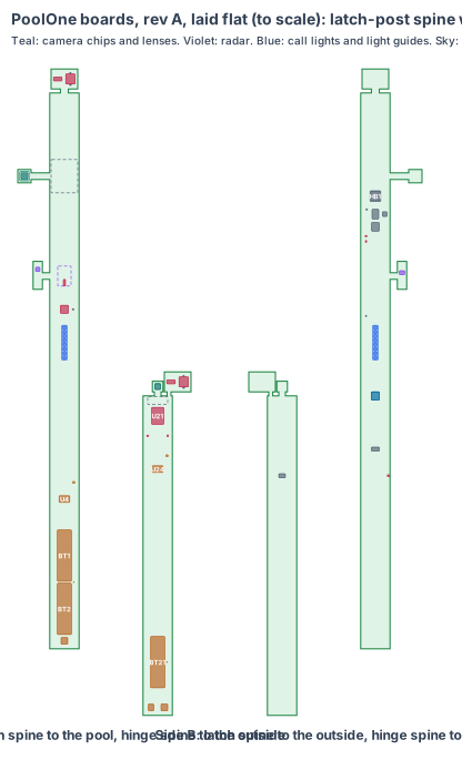
The pool gate’s two posts are the product. Each now carries one board of our own with every chip soldered on it, shaped as a narrow spine that stands up the inside of its 50 × 50 × 2 aluminium post (46 × 46 bore). The bench build used two Raspberry Pi Zero 2 W boards, two Camera Module 3 Wide, an HLK-LD2450 radar module, a DRV5055 Hall board, NeoPixel sticks, an ATECC608 breakout and a Pololu buck; none of them stays. There are no plugs, ribbons or adapters inside, only latched leads to the 12 V supply and between the posts.
| Board | Core (products/PCB-PLATFORM.md) | Where |
|---|---|---|
| Latch-post board | V1 (RV1126B) + one C1 camera chip + a 60 GHz radar chip | a spine up the latch post, 740 to 1,575 mm, 11 mm towards the outside face |
| Hinge-post board | S1 (ESP32-S3 module) + one C1 camera chip | a spine up the hinge post, 640 to 1,120 mm, 11 mm towards the pool face |
The board sheet first listed PoolOne as V1 + C1 only. The hinge post’s camera is 1.1 m from the brain, across the gate leaf: far too long for a camera lane. So the hinge post gets the S1 core, which compresses its frames and sends them over the wired link in the conduit under the gate, and the RV1126B runs the outside models on them. Every number marked est. is measured on the first boards (rev A).
1. The shape
Latch-post board. An 8-layer spine, 44 × 835 mm, side A to the pool, side B to the outside wall (10.9 mm of room on side B, 32.9 mm on side A). Three pieces bend off it:
- Pool head: a 20 × 20 mm head on a flex (about 40 mm, est.), its face tilted 20° down to the pool. The Sony IMX415 camera chip sits under an M12 lens whose front is just inside the 27 × 27 pool-face window.
- Radar head: a 14 × 42 mm head on a flex (about 45 mm, est.), flat against the inside of the pool face behind the radome slot: the TI IWRL6432AOP radar chip and the Wi-Fi/BT chip antenna, 0.3 mm behind the PC.
- Top tab: 40 × 30 mm, folded flat under the cap: the tamper switch, pressed 0.5 mm by the cap, and the latched microSD card, reached by lifting the cap.
Hinge-post board. A 4-layer spine, 44 × 480 mm, side A to the outside face, with an outside head (16 × 16 mm, tilted 35° down, its M7 lens just inside the 27 × 27 outside window) and a top tab under the cap (tamper switch, microSD) on a flex that runs past the head (about 120 mm, est.).
2. What is on the boards
| Job | Latch post | Hinge post |
|---|---|---|
| Brain | Rockchip RV1126B, 2 GB LPDDR4X, 32 GB eMMC, RK806-class power chip, MEMS clocks; copper heat block to the outside wall | ESP32-S3-WROOM-1-N16R8 module |
| Cameras | Sony IMX415 8 MP, 110° × 77° M12 lens, 20° down: the deck, the water, the gate area | OmniVision OV2640, 100° M7 lens with rows cropped to 1600 × 720, 35° down: the 900 mm strip outside |
| Radar | TI IWRL6432AOP 60 GHz, antennas in the package, behind the radome slot | none |
| Gate | TI TMAG5273 3D Hall chip at the gate-face edge, 16.5 mm from the leaf magnet | none |
| Calls shown | 8 RGB LEDs on each face under light guides to the opal slots; sounder under the outside tone holes | none (the latch post shows every call) |
| Radio | AMPAK AP6256 Wi-Fi 5 + BT 5, chip antenna on the radar head | module antenna under the outside window, setup only |
| Link | TI THVD1450 RS-485, 4-circuit latched Micro-Fit lead (12 V, ground, the pair) | the same, plus a 2-circuit latched lead from the buried 12 V supply |
| Security | ATECC608B, ID chip, Omron D2F-01 tamper switch under the cap | the same |
| Software | latched microSD under the cap (our software), eMMC fallback | latched microSD under the cap |
| Power | 12 V buck, BQ24074 charger, two soldered 18650 holders with a thermistor | 12 V input with TVS and fuse, buck, BQ24074, one 18650 holder with a thermistor |
The full list with every size and source is poolone-board-parts.csv.
3. Every connection, checked
- IMX415 to the RV1126B: 4-lane MIPI CSI-2 along the pool head’s flex (short, under 60 mm).
- OV2640 to the ESP32-S3: its 8-bit camera port along the outside head’s flex; JPEG is made in the camera chip.
- Hinge post to latch post: RS-485 at up to 10 Mbps over about 3 m of lead in the conduit under the gate; about 1.9 Mbps of frames at 2 fps.
- Radar to the RV1126B: SPI and a wake line along the radar head’s flex; the antenna feed runs on the same flex as a 50 Ω line.
- Hall chip, security chip, ID chip: I2C on the spine.
- Every mating pair (lens holders on the chips, latched headers and their leads, the microSD socket) is checked against the makers’ drawings before the schematic, never as “the same as” another product (lesson from the Radxa camera short, 3 Nov 2026).
4. Heat
The processor’s 1.5 W goes through a copper block and gap pad to the post’s outside wall: the aluminium post is the heat sink. Pool fence posts are often black. With an IR-reflective (“cool”) black powder coat the wall reaches about 58 °C in 40 °C sun (est.), the processor about 67 °C (rated 85 °C). The cells stand low in the post, 760 to 920 mm, and reach about 56 °C (est.; limit 60 °C); charging holds above 45 °C. Both are measured in a sun box on rev A (lesson: sun).
5. Power budget (est.)
| State | Latch post | Hinge post |
|---|---|---|
| Watching | 2.4 W (RV1126B, IMX415 at 5 fps, radar, Wi-Fi) | 0.6 W (ESP32-S3, OV2640 at 2 fps, link) |
| A call showing | +1.6 W of lights and tone | none |
| Power cut | 1.2 W (pool camera 2 fps, the radar wakes it): 11.5 h on two cells aged and cold | 0.45 W (1 fps): 15.3 h on one cell |
12 V from a listed plug-in supply (24 W, est.) on the pump pad’s GFCI outlet, through the buried low-voltage lead into the hinge post; the link lead carries it on. About 12 W at most while the cells recharge after a cut.
6. Factory test (every board, every time)
Spring-pin fixture on the factory pads: rails and current at 12 V, the card boots our test image, both cameras give a frame of a test chart, the radar sees a corner reflector at 2 m, the Hall chip reads a magnet on the fixture, every LED and the sounder, the security chip answers, the tamper switch opens and closes, the link passes frames both ways, the chargers charge a test cell and stop when the thermistor is warmed.
7. Who makes what
Same as every board: the maker finishes the schematic and layout from our board code and the V1, S1 and C1 core circuits, makes and assembles the boards, codes the coating masks and runs our factory test. We write the software and test the boards in real posts.
8. Cost per gate, electronics (est.)
Latch-post board about $80 and hinge-post board about $25 at 1,000 sets, about $105 a gate (est.; V1 and S1 core costs from products/PCB-PLATFORM.md section 5, plus the IMX415, radar chip, Hall chip, cells and holders).
9. Timeline
Shape and placement are done. Schematic, footprints and routing follow CricketOne’s board, which goes first; rev A PoolOne boards are made after CricketOne’s.
10. Still to check
- The rev T CAD: the board inside both posts, every part checked in 3D (lesson: fit3d).
- Wi-Fi range from the radome slot in an aluminium post to a home router 15 m away.
- The Hall field at each gate position, and a second magnet held to the post.
- Cell and processor temperature in a black post in full sun.
- The power-cut run time on the dev kit.
Sources
- ISPSC Section 305 barrier summary
- Sony IMX415
- TI IWRL6432AOP
- TI TMAG5273
- TI THVD1450
- Rockchip RV1126B module (Forlinx FET1126Bx-S)
- Espressif ESP32-S3-WROOM-1
- Samsung INR18650-35E
Design review (4 Nov 2026)
Every board is checked by the same rules (products/_shared/board-rules.mjs), one for each lesson any of our boards has taught us. PoolOne’s boards were made with every rule from the start: 19 pass, 3 fixed, 9 to prove, 0 fail. The full review, with every number and its source, is on the board page. It shows:
- Radar window (fixed): the first CAD put the radar behind a 1 mm aluminium skin. A 60 GHz radar does not see through metal at all, so the slot now goes right through the pool face with a 1.5 mm PC radome bonded in (rev T CAD, 4 Nov 2026). The Wi-Fi antenna shares it.
- Cameras: a child’s head is about 29 px across at the far corner of a 4 × 8 m pool, 10.3 m away, on the IMX415; the outside camera sees a head at the edge of the 900 mm strip with plenty of pixels.
- Windows (lesson): each lens front sits just inside its 27 × 27 window. The outside lens was chosen from its calls: rows cropped to 1600 × 720 keep the view down to the strip inside the 64.8° the window’s edge leaves.
- Views: the pool corners, the deck inside the gate, a head on the deck, the fence line and the strip outside are all in view from where the chips sit.
- Clocks and card: MEMS oscillators, a latched microSD under each cap.
- Power cut: about 11.5 h in the latch post and 15.3 h in the hinge post, cells aged and cold (to prove on the dev kit).
- Fast lines on a solid ground plane (to prove, lesson: planes, from the CricketOne test-board layout of 4 Nov 2026): RV1126B memory; 3 camera MIPI links (100 Ω pairs); USB (90 Ω); antenna feed (50 Ω, keep-out on every layer); card lines (length-matched, no vias under the socket). Ground on the layer next to the parts (inner layer 1, supply on inner layer 2; the whole bottom of a 2-layer section), one via beside each ground and supply pad and none in pads, no copper or vias in the antenna keep-out on any layer or under the card socket, the impedance lines routed first with a test coupon. The quote asks for it; the routed board’s design rule check proves it.
The request for quote is /build/poolone-quote.
New shared rule (4 Nov 2026, from PumpOne): antennas outside metal boxes. A radio inside a closed metal enclosure now fails the review unless its antenna is outside the metal. This board’s antennas already use the PC radome slot in the latch post and the outside camera window in the hinge post, so the check passes and the review names the window (lesson: enclosure).