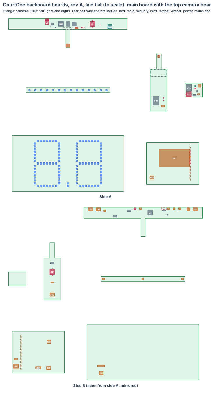
CourtOne: circuit boards of our own
What changed (4 Nov 2026). The rev A bench backboard is built from bought boards joined by leads and ribbons: a Raspberry Pi Zero 2 W with an RGB Matrix Bonnet and the Raspberry Pi AI Camera in the top rail, two Seeed XIAO ESP32-S3 Sense corner cameras, a XIAO nRF52840 Sense in the ring box, NeoPixel strips round the frame, two bought 64 × 32 LED panels on ribbons and an enclosed Mean Well LRS-50-5 in the clock box. CourtOne now gets boards of our own, like CricketOne, on our board platform. The same set goes in both backboards; the home board’s main board is the brain and keeps the signed call log.
- The chips: the V1 core (Rockchip RV1126B, 2 GB LPDDR4X, 32 GB eMMC, AMPAK AP6256 Wi-Fi/BT) with a bare Sony IMX415 8 MP top camera chip (C1); in each side rail the S1 core (ESP32-S3-WROOM-1 with 8 MB PSRAM) with a bare OmniVision OV5640 5 MP corner camera chip; an ESP32-S3-MINI-1 with the ST ISM330DHCX motion chip on the rim board; 406 RGB call-light LEDs on 29 light sections; 200 red LEDs on the two digit boards; a PCB-mount Mean Well IRM-60-5.
- The shape: in the top rail, one rigid-flex piece: an 8-layer main board (340 × 32 mm) flat in the rail with a 12 × 12 mm top camera head on a 40 mm flex, tilted 51° down at the ring, the key and the arc. In each side rail a 4-layer corner board (48 × 120 mm) standing at 540 to 660 mm with a 14 × 14 mm corner head on a 30 mm flex. A 4-layer rim board (50 × 40 mm) on the plate-side wall of the ring box. Twenty-nine 2-layer light sections (240 × 14 mm) over the frame’s light slots. In the clock box, two 4-layer digit boards (320 × 160 mm) behind the windows and a 2-layer power board (150 × 120 mm) standing between them.
- The top camera window (fixed): the rev O Ø16 disc was never checked against the calls. The ball through the net is 74° below level, so its line of sight leaves the front face far below the lens. With an M8 lens low in the rail, its front 0.5 mm inside the face, the window becomes an 18 × 39 slot from 1,018.5 to 1,057.5 mm and passes every call with 1 mm to spare (rev T CAD, the same day).
- The corner windows move to the side faces (fixed): rev O put the corner cameras behind Ø12 windows in the front face, turned 55° out; the corner 0.6 m in front of the board is 84° from that face, so no window there could pass it. In each side rail’s outer face the steepest corner call is 61° from the face (24 × 22 windows, rev T CAD).
- Radio out of the aluminium (fixed): the frame is a closed aluminium tube, so the Wi-Fi antenna sits at the main board’s back edge behind a new Ø20 radio window in the top rail’s back face (lesson: enclosure).
- Made from the shared rules: MEMS clocks, the latched microSD card with our software on every board, conformal coating, the antenna checked on rev A, the camera chip 30 mm or more from the processor, each lens chosen from the calls and its front just inside the face (lesson: window).
The bench backboards stay the test rig until the boards arrive.
1. The shape: one set per backboard
| Piece | Size | Layers | Where | What |
|---|---|---|---|---|
| Main board | 340 × 32 mm, 1.6 mm | 8 | flat in the top rail, y 24 to 56, side A up, 10 mm over the light rows | the V1 core, Wi-Fi/BT, card, security, tamper, call tone, links, light drivers, leads |
| Top camera head | 12 × 12 mm, 0.8 mm, on a 40 mm flex | 8 | off the main board’s front edge at x 0, tilted 51° down | IMX415 and M8 lens holder, lens front 0.5 mm inside the front face |
| Corner board (2) | 48 × 120 mm, 1.6 mm | 4 | standing in each side rail at 540 to 660 mm, side A out (the left one turned round) | ESP32-S3, security and ID chips, links, card, lead |
| Corner camera head (2) | 14 × 14 mm, 0.8 mm, on a 30 mm flex | 4 | turned 30° from the side face to the court and 30° down | OV5640 and M8 lens holder, lens front 0.5 mm inside the side face |
| Rim board | 50 × 40 mm, 1.6 mm | 4 | on stand-offs on the plate-side wall of the ring box | ESP32-S3-MINI-1, ISM330DHCX, link, card, lead |
| Light section (29) | 240 × 14 mm, 0.8 mm | 2 | over the 12 mm slots: 7 red and 7 yellow in the top rail, 7 in the bottom rail, 4 in each side rail | 14 RGB LEDs, chain in and out |
| Digit board (2) | 320 × 160 mm, 1.6 mm | 4 | 4 mm behind each clock window (the back one turned round) | 2 digits and a point in 100 red LEDs |
| Power board | 150 × 120 mm, 1.6 mm | 2 | standing in the clock box between the digit boards | mains terminal, fuse, varistor, IRM-60-5, creepage slot, three leads |
Leads: the clock lead (clock box to the main board, 5 V on two pins each way and the digit data, about 0.6 m of 18 AWG, Molex Micro-Fit 3.0 6-circuit latched, through the Ø20 hole in the back face); a corner lead to each corner board (about 1.2 m, 6-circuit: 5 V, GND, RS-485 and the frame-sync pair); the rim lead (about 2.1 m, 4-circuit, out of the ring box top and in at the bottom rail); five light chains on JST GH 3-pin latched leads (5 V, GND, data); the two digit leads from the power board.
2. What is on the boards
Main board, side A (up): RV1126B (U1) with a 16 × 16 copper heat block to the top rail’s top wall (HB1), LPDDR4X (U10), eMMC (U5), RK806 class power (U3), 24 MHz MEMS oscillator (Y1), the AP6256 Wi-Fi/BT module (U6) and its 37.4 MHz MEMS oscillator (Y2) with the chip antenna (AE1) at the back edge facing the radio window, ATECC608B (U2) and ID chip (U9, which also says home or away), the latched microSD (J1) under the service cover, the DRV5032 cover tamper switch (U7), the SMD piezo (BZ1) under a printed sound tube (GK1) to the tone holes, the IMX415 supplies (U21) and a keep-out under the head’s flex (TKO).
Main board, side B (down): the decoupling field (C1), three THVD1450 RS-485 transceivers (U14 to the corner boards with the frame sync, U15 to the rim board), two SN74AHCT125 line drivers for the five light chains and the clock digits (U36), the eFuse (U42), the latched clock lead (J2), corner leads (J3, J4) and rim lead (J5), the five light headers (J6 to J10), the antenna keep-out (ANT1) and the factory pads (TP1).
Top camera head: the IMX415 (U12) under an M8 lens holder with an 80° × 50.6° lens (L1).
Corner board: ESP32-S3-WROOM-1-N16R8 (U41, radio off: inside the aluminium rail the link is the wire), the 3.3 V buck and OV5640 supplies (U43), ATECC608B (U44, signs every frame it sends), ID chip (U45, left or right), two THVD1450 (U42C), the latched microSD (J41), the corner lead (J42) and factory pads (TP41). Corner head: the OV5640 (U46) under an M8 lens holder with a 60° × 46.8° lens (L41).
Rim board: ESP32-S3-MINI-1-N8 (U51), ISM330DHCX (U52) on the board screwed flat to the plate-side wall, THVD1450 (U53), the 3.3 V buck (U54), ID chip (U55), the latched microSD (J51), the rim lead (J52) and factory pads (TP51).
Light section: 14 WS2812B-class LEDs at 17 mm pitch (D1 to D14) over the slot; chain in and out (J61, J62) and a bulk capacitor (C61).
Digit board: two 7-segment digits of 130 × 70 mm with 7 LEDs a segment (DS…) and the point (DP1, DP2), the latched lead (J71) and a 1.5 A polyfuse with bulk capacitors (C71).
Power board: the push-in 3-pole mains terminal (J81) for the shot-clock feed, a 2 A slow-blow fuse and a varistor (F1A), the IRM-60-5 (PS1), the milled creepage slot (SLOT), the clock lead (J82) and the two digit leads (J83, J84), and the output filter (C81).
3. Every connection, checked
| Link | How | Checked against |
|---|---|---|
| Top camera chip to RV1126B | 4-lane MIPI CSI-2 across the 40 mm flex | IMX415: 3840 × 2160 at 30 fps uses 2.49 of 3.56 Gbps |
| Corner camera chip to ESP32-S3 | 8-bit camera port across the 30 mm flex, the OV5640 cropping to 2592 × 800 and making JPEG | OV5640 data sheet; ESP32-S3 LCD_CAM (est. 48 MHz pixel clock) |
| Corner boards to the main board | RS-485 at up to 4 Mbps, frames on request; a frame-sync pair | TI THVD1450; ESP32-S3 UART (up to 5 Mbps) |
| Rim board to the main board | RS-485, rim and net hits as events | TI THVD1450 |
| Call lights and digits | five light chains and the digit line through 3.3 → 5 V line drivers | WS2812B data sheet; TI SN74AHCT125 |
| Wi-Fi/BT | SDIO and UART on the main board | AMPAK AP6256 (RV1126B SDK) |
| Home to away backboard | Wi-Fi, every call signed by the sending board’s security chip | AP6256; ATECC608B |
| Power in | the shot-clock mains feed (120 or 230 V) into the push-in terminal, fuse, varistor, IRM-60-5 (Class II); the clock lead drops 0.08 V at 6.5 A | Mean Well IRM-60 data sheet (to read) |
| Cards | SD bus to the RV1126B; SPI to each ESP32-S3; latched sockets | Amphenol 101-00660 family drawing |
Every mating pair is checked against the makers’ documents, never “same as” another board.
4. Heat
The aluminium frame is the heat sink: about 2.2 W from the RV1126B goes through the heat block into the top rail’s top wall (4 K/W est.), so the chip sits near 45 °C with the rail at 36 °C in a full summer gym. The top camera chip is 46 mm from the processor. The IRM-60-5 sits in the closed clock box at about 24 % load in play; its temperature there is logged on rev A.
5. Power budget per backboard (est.)
| State | Draw |
|---|---|
| In play: main board, top camera, Wi-Fi | 2.7 W |
| Two corner boards (OV5640 and ESP32-S3) and the rim board | 1.9 W |
| Both clock faces showing red digits | 7.2 W |
| End of a period: red rows all round and the yellow row at the 0.9 A chain cap, for 3 s | +22.5 W |
| Peak | 34.5 W, 69 % of the 35 W allowed (50 W supply) |
6. Factory test (every board, every time)
Spring-pin fixture on TP1, TP41 and TP51: 5 V in, the eFuse trip at 5 A, every rail, boot from the card, a frame of a test chart from the top camera and each corner head, the motion chip on a tap table, every LED on every section and digit board, the piezo against a sound-level meter, the tamper switch with a magnet, the security chips’ keys, the ID chips set to home or away and left or right. The power board is tested on its own behind an isolating transformer: hi-pot across the slot, 5 V under load.
7. Who makes what
One maker makes the two rigid-flex pieces and the small boards and assembles them (turnkey), and makes the leads to length. We supply the microSD cards with our software and the lenses focused for the court (est.). The quote pack is /build/courtone-quote.
8. Cost per backboard, electronics (est.)
| Item | Per backboard |
|---|---|
| V1 core (RV1126B, LPDDR4X, eMMC, power, AP6256) | $30 |
| IMX415 chip, M8 holder and lens | $14 |
| Two corner boards’ chips (ESP32-S3, OV5640, lens, security) | $34 |
| Rim board’s chips (ESP32-S3-MINI-1, ISM330DHCX) | $11 |
| 606 LEDs, line drivers and their supply parts | $24 |
| IRM-60-5, mains terminal, fuse, varistor | $22 |
| Boards (two rigid-flex pieces, rim, 29 sections, 2 digit boards, power), 1,000 sets | $45 |
| Leads | $10 |
| Assembly and test | $25 |
| Four microSD cards with our software | $12 |
| Total | about $227 (est.) |
The bench backboard’s bought boards cost about $320 at qty 1 (Pi Zero 2 W, AI Camera, Matrix Bonnet, two LED panels, three XIAO boards, NeoPixel strips and the LRS-50-5), so our set is about $90 cheaper per backboard at 1,000 (est.).
9. Timeline
| Step | When |
|---|---|
| Shape and placement (this page) | done, 4 Nov 2026 |
| Rev T CAD: top camera slot, corner windows in the side faces, radio window, tone holes and the mains gland (drawn the same day); head brackets, magnet boss and the board set in the CAD next | next |
| Schematic, footprints, routing | Dec 2026 – Jan 2027 |
| Rev A boards made and tested on one court | Mar 2027 (est.) |
10. Still to check
- The IMX415 behind an M8 lens for a 1/2.8-inch chip: a lens with 80° across and its sharpness at 8 m (est. until chosen).
- The OV5640 crop and JPEG rate into the ESP32-S3 camera port, and the 4 Mbps frame transfer time on the dev kit.
- Wi-Fi range from the radio window in the top rail’s back face to the scorer’s table and the other backboard.
- The power board’s creepage and clearance once routed (IEC 62368-1), and the IRM-60-5’s temperature in the closed clock box.
- The call lights’ and digits’ brightness from the far end of the court; FIBA 1.1.6, 1.1.7 and 5.6 read against them.
Sources
- FIBA Official Basketball Rules 2026, Basketball Equipment: https://assets.fiba.basketball/image/upload/documents-corporate-fiba-official-rules-2026-equipment-v1-0.pdf
- Rockchip RV1126B: https://www.rock-chips.com/
- Sony IMX415: https://www.sony-semicon.com/en/products/is/security/index.html
- OmniVision OV5640: https://www.ovt.com/
- Espressif ESP32-S3-WROOM-1 and ESP32-S3-MINI-1: https://www.espressif.com/en/products/modules
- ST ISM330DHCX: https://www.st.com/en/mems-and-sensors/ism330dhcx.html
- AMPAK AP6256: https://www.ampak.com.tw/
- Mean Well IRM-60: https://www.meanwell.com/
- Worldsemi WS2812B: http://www.world-semi.com/
- TI THVD1450: https://www.ti.com/product/THVD1450
- Microchip ATECC608B: https://www.microchip.com/en-us/product/atecc608b
- TI DRV5032: https://www.ti.com/product/DRV5032
- The backboard: products/courtone/cad/courtone-cad.mjs (rev O; windows, tone holes, radio window and gland rev T); the boards: products/courtone/hardware/pcb/courtone-board.mjs
Design review (4 Nov 2026)
Every board is checked by the same rules (products/_shared/board-rules.mjs), one for each lesson any of our boards has taught us. CourtOne’s boards were made with every rule from the start: 24 pass, 4 fixed, 13 to prove, 0 fail. The full review, with every number and its source, is on the board page. It shows:
- The top camera window (fixed): the ball through the net is 74° below level; an M8 lens low in the rail and an 18 × 39 slot pass every call with 1 mm to spare. Drawn in the CAD the same day.
- The corner windows (fixed): from the front face the corner calls were up to 84° off; in the side faces the steepest is 61°.
- Pixels: a shoe on the arc 30° off centre gets 33 px from the top camera and a shoe at the wing 33 px from a corner camera, against 20 needed.
- The latched microSD is fitted on the main, corner and rim boards, and our software starts from it; updates never run during a game.
- Conformal coating on every board, the power board’s mains side included.
- Fast lines on a solid ground plane (to prove, lesson: planes, from the CricketOne test-board layout of 4 Nov 2026): RV1126B memory; 5 camera MIPI links (100 Ω pairs); USB (90 Ω); antenna feed (50 Ω, keep-out on every layer); card lines (length-matched, no vias under the socket). Ground on the layer next to the parts (inner layer 1, supply on inner layer 2; the whole bottom of a 2-layer section), one via beside each ground and supply pad and none in pads, no copper or vias in the antenna keep-out on any layer or under the card socket, the impedance lines routed first with a test coupon. The quote asks for it; the routed board’s design rule check proves it.
- To prove on rev A: the AI time per frame, the corner frames’ transfer time, Wi-Fi through the radio window, the call lights and digits from across the court, the mains creepage and the supply’s temperature in the clock box, the tamper magnet, the head brackets and the boards in the rev T CAD.
The request for quote is /build/courtone-quote.