CareOne: one circuit board of our own
What changed (4 Nov 2026). The rev A bench locker is built from bought boards joined by leads: a XIAO ESP32-S3, an HLK-LD2450 radar module, two NAU7802 load-cell boards, a MAX9814 mic board, a 16 mm panel key, two NeoPixel sticks, a piezo, an ATECC608 board and a PowerBoost 1000C charger. CareOne now gets one circuit board of our own, like CricketOne and BedsideOne, with every chip placed straight onto it, made with every shared design-review rule from the start.
- The chips: the ESP32-S3 certified radio module (soldered by its edge pads), a TI IWRL6432AOP 60 GHz radar chip with its antennas built in, two Nuvoton NAU7802 weigh chips, a sealed call-key switch, a MEMS mic, 16 LEDs (call light and floor glow), a sounder, the security chip, the tamper switch, a charger and two soldered 18650 cell holders. No camera: residents’ rooms are private (CQC surveillance guidance).
- The shape: everything but the floor glow lives in the locker’s sealed 70 mm top. A top board (453.8 × 435.8 mm, 4 layers) lies 8 mm over the printed service tray, notched round the two load-cell blocks. A front strip bends 90° up 4 mm behind the front face (call light and sounder). A small radar tab bends up 65° from a recess in the front corner on the bed side, so the radar chip looks 25° down at the bed and the floor beside it. A side strip bends 90° up 6 mm behind the bed-side face, with the call key and the mic. A 12 mm glow tail (about 684 mm, est.) runs from a tongue in the bed-side edge down the inside of the bed-side panel to a glow strip behind the floor-glow skin.
- No mains in the locker. 5 V comes from a listed USB adapter at the wall on one latched lead, as before (UL 962). The bed’s own nurse-call cord stays the life-safety call (UL 1069).
- The rev A bench locker stays as it is. It proves the calls and the software, which move to this board (same ESP32-S3 family).
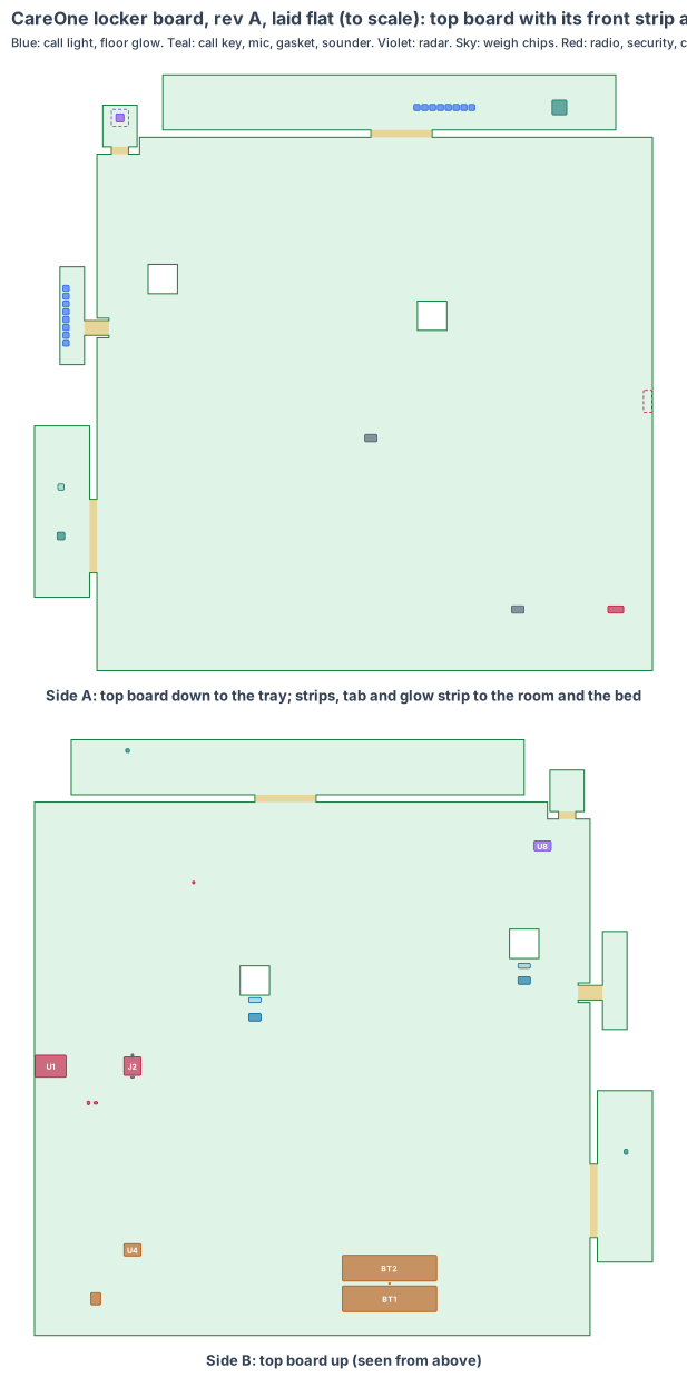
The board is code (hardware/pcb/careone-board.mjs). It writes the KiCad board file (hardware/pcb/careone-board.kicad_pcb), the parts list (careone-board-parts.csv) and this drawing, and checks every part:
- every part sits on its board with a 0.3 mm edge margin and no two parts overlap on the same side; no part sits in the notches round the load-cell blocks, the radar recess or the glow-tail slot, and nothing under the load-cell bars or the plate stems reaches them;
- every part’s height fits its gap: 7.6 mm under the top board, 49.9 mm above it, 3.5 mm in front of the front strip, 5.5 mm in front of the side strip, 2.5 mm in front of the glow strip;
- the call-light LEDs sit behind the opal skin, the sounder on the tone holes, the call-key switch under the key, the mic and its gasket on the mic port, the tamper switch on the tray boss and the floor-glow LEDs behind the floor-glow skin (within 1 mm, from cad/careone-cad.mjs);
- the radar chip, on the bent tab, is centred on the radar window in 3D, every tab corner and the chip’s front corners stay 3.8 mm or more inside the front face, and all seven radar calls in the CAD are inside the chip’s view (worst: the carer at the bedside at 30° up, against ±40°; lying in bed at 38° across, against ±70°);
- the folds stay inside the locker top: both strips below the top skin, the front strip clear of the right skin and the radar tab, the side strip clear of the tab and the back; the glow tail runs down 4 mm inside the bed-side panel and the glow strip stays above the cupboard floor, inside the back and the door;
- the radio module’s antenna end is at the top board’s right edge (away from the bed) with a keep-out under it; the charger and the radar rails are 20 mm or more from both weigh chips.
KiCad design rule check: 0 violations (KiCad 10, 4 Nov 2026). Each part is drawn at its real size, as a placeholder outline until its full footprint is added. Numbers marked est. are estimates.
1. The shape: five pieces on one board
| Piece | Size | Where | Side A | Side B |
|---|---|---|---|---|
| Top board | 453.8 × 435.8 mm, 4 layers | flat 8 mm over the service tray (z 802) | down to the tray: tamper switch, factory pads, antenna keep-out | up: radio, security, ID, microSD, power lead, charger, cells, weigh chips, radar rails |
| Front strip | 370 × 45 mm, 2 layers, on a 50 mm flex | bent 90° up, side A 4 mm behind the front face | to the room: 8 call-light LEDs, sounder | sounder driver |
| Radar tab | 28 × 34 mm, 2 layers, on a 14 mm flex | bent 65° up from the front corner on the bed side | 25° down to the bed: IWRL6432AOP and its keep-out | — |
| Side strip | 140 × 45 mm, 2 layers, on a 60 mm flex | bent 90° up, side A 6 mm behind the bed-side face | to the bed: call-key switch, mic gasket | mic |
| Glow strip | 80 × 20 mm, 2 layers, on a 12 mm tail about 684 mm (est.) | 3 mm inside the bed-side panel, z 110 to 130 | to the bed: 8 floor-glow LEDs | — |
2. What is on the board
| Ref | Part | Job |
|---|---|---|
| U1 | Espressif ESP32-S3-WROOM-1-N16R8 | the brain and Wi-Fi: every call, the voice notes, signed alerts to the carers’ app |
| U3 | TI IWRL6432AOP 60 GHz radar, antennas in package | bed exit, not back, someone on the floor, turns, night checks, the carer at the bedside |
| U8 | Radar rails (LP87745 class), 40 MHz crystal, 2 MB flash | the radar’s own power and program |
| U5, U6 | Nuvoton NAU7802 ×2 with gauge-wire pads | drinks from the jug (fluid chart), hand rubs from the bottle |
| SW2 | C&K KSC sealed tact switch under a flush key | the call key: press = help, hold = a voice note |
| MK1, GK1 | Infineon IM69D130 MEMS mic and gasket | the voice note while the key is held |
| D1–D8 | WS2812B-class LEDs | the call light: yellow, green, amber, red |
| D9–D16 | WS2812B-class LEDs | the amber floor glow at night |
| LS1, Q1 | 12 mm sounder and driver | the call tone |
| U2, U9 | Microchip ATECC608B, ID EEPROM | signs every call; board identity and calibration |
| SW1 | Omron D2F-01 | tamper: opens when the service tray is taken off |
| J2 | Latched microSD | our software starts from the card |
| J1, U4 | Micro-Fit 2-pin lead, BQ24074 charger, TPS63020 | 5 V in from the listed adapter, power path, 3.3 V |
| BT1, BT2, RT1 | Two Keystone 1042 holders, Samsung INR18650-35E, NTC | backup through a power cut; no charging outside 0–45 °C |
3. Every connection, checked
| Mating pair | Checked against | Note |
|---|---|---|
| Adapter lead → J1 | Molex Micro-Fit 3.0 drawing | latched, keyed; the adapter’s lead is made with the Micro-Fit plug |
| Load-cell gauge wires → PD1, PD2 | load cell maker’s colour code | soldered, with a strain-relief slot; no plug |
| Key cap → SW2 | C&K KSC drawing (to read) | printed cap in the Ø16.4 hole, made in the rev T CAD |
| Mic gasket → bed-side skin port | IM69D130 port size | Ø3 port with a membrane added in rev T |
| Tray boss → SW1 | Omron D2F drawing | the bench tray post becomes a 1.5 mm boss in rev T |
No module, ribbon, adapter or plug inside the locker; the only lead is the 5 V lead from the wall.
4. Heat
About 1.1 W watching (est.) in a sealed top with no vents (wipe-clean, HBN 00-09). The ESP32-S3 at 0.5 W sits about 13 K over a 30 °C room (est.). The charger and the radar rails are kept 20 mm or more from the weigh chips so the gauges do not drift; the cells sit at the back, away from both.
5. Power budget (est.)
| State | Draw | Note |
|---|---|---|
| Watching (mains) | 1.1 W | radar tracking, Wi-Fi, weigh chips |
| Call (mains) | + 1 W | call light and tone |
| Charging | + 3.6 W | BQ24074 at 1 A |
| Power cut | 0.55 W | radar in low-power tracking, Wi-Fi only for calls, light dim: about 27 h on two cells aged to 80 % |
Under 70 % of a 12 W listed adapter in every state.
6. Factory test (every board, every time)
Spring pins on TP1 and TP2: rails and current, flash our loader, read the ID chip and the security chip, boot from a test card, light every LED, sound the tone, press the key, record a tone on the mic, read both weigh chips with a fixture load, see a corner reflector on the radar, open and close the tamper switch, charge and discharge the cells.
7. Who makes what
The board maker builds and assembles the rigid-flex board, fits the cells and runs the factory test; we supply the tested card image and the test fixture design. The locker maker fits the board, the load cells, the key cap and the tray.
8. Cost per locker, electronics (est.)
About $64 for the board with its parts at 1,000 lockers (est.): radar chip and its rails about $18, ESP32-S3 module $4, two weigh chips $4, LEDs, key, mic and sounder $6, power, charger and cell holders $6, two cells $8, the rigid-flex board with its long tail $18. The bench boards it replaces cost about $150 at one off.
9. Timeline
Shape and placement done (4 Nov 2026); schematic and footprints next; routing and the maker files after; rev A boards in March 2027 (est.).
10. Still to check
- The IWRL6432AOP outline and the radar view edge on TI’s evaluation board beside a real care bed.
- The laminate skin over the radar at 60 GHz (set from the measured permittivity).
- The C&K KSC outline, key travel and cap.
- The rev T locker CAD: the 1.5 mm tray boss, the tray slot for the glow tail, the clip channel past the drawer, the mic port and the radar skin, with every board part checked in 3D.
- Wi-Fi range from lockers with steel frames, on rev A.
Sources
- Espressif ESP32-S3-WROOM-1 datasheet: https://www.espressif.com/sites/default/files/documentation/esp32-s3-wroom-1_wroom-1u_datasheet_en.pdf
- TI IWRL6432AOP: https://www.ti.com/product/IWRL6432AOP
- Nuvoton NAU7802: https://www.nuvoton.com/products/smart-home-audio/audio-converters/precision-adc-series/nau7802sgi/
- Omron D2F: https://omronfs.omron.com/en_US/ecb/products/pdf/en-d2f.pdf
- C&K KSC series: https://www.ckswitches.com/products/switches/product-details/Tactile/KSC/
- Samsung INR18650-35E: https://www.18650batterystore.com/products/samsung-35e-18650-3500mah-8a-battery
- TI BQ24074: https://www.ti.com/product/BQ24074
- Locker sizes and windows: products/careone/cad/careone-cad.mjs
Design review (4 Nov 2026)
Every board is checked by the same rules (products/_shared/board-rules.mjs), one for each lesson any of our boards has taught us. CareOne’s board was made with every rule from the start, so nothing had to be fixed: 8 pass, 2 fixed, 10 to prove, 0 fail. The full review, with every number and its source, is on the board page. It shows:
- Radar view: all seven radar calls are inside the chip’s view, the closest (the carer at the bedside) 10° from its edge; to prove on TI’s evaluation board beside a real care bed. The bench radar was turned 40° to the bed and tilted 25°; our chip’s wider view needs only the 25° tilt, so the tab bends on one fold.
- Power cut: two cells give about 27 h, aged to 80 % (to prove on rev A; target 24 h), so bed-exit and floor calls keep going through a cut.
- The latched microSD (J2) is fitted, and our software starts from it; updates run only in the day shift.
- Conformal coating against jug spills and daily disinfectant wipes is asked for in the quote.
- Wi-Fi through the laminate side skin is measured on rev A, because some ward lockers have steel frames.
- The tamper boss, the call-key travel, the radar skin and the long glow tail are checked in the rev T CAD and on rev A.
- Fast lines on a solid ground plane (to prove, lesson: planes, from the CricketOne test-board layout of 4 Nov 2026): USB (90 Ω); antenna feed (50 Ω, keep-out on every layer); card lines (length-matched, no vias under the socket). Ground on the layer next to the parts (inner layer 1, supply on inner layer 2; the whole bottom of a 2-layer section), one via beside each ground and supply pad and none in pads, no copper or vias in the antenna keep-out on any layer or under the card socket, the impedance lines routed first with a test coupon. The quote asks for it; the routed board’s design rule check proves it.
The request for quote is /build/careone-quote.