GarageOne: circuit boards of our own
What changed (4 Nov 2026). The rev A bench head is built from bought boards joined by leads: a Raspberry Pi Zero 2 W, a Camera Module 3 Wide on a ribbon, an MLX90640 board, a MAX9814 mic board with an MCP3008 ADC, an SHT45 board, an ATECC608 board, two NeoPixel sticks, a piezo, a D2F-01 switch, an IRM-10-5 and an 18650 with a charger board. GarageOne now gets boards of our own, like every IEMI product, with the chips soldered straight on them:
- The chips: the V1 core (Rockchip RV1126B, 2 GB LPDDR4X, 16 GB eMMC, AMPAK AP6256 Wi-Fi/BT module), a bare Sony IMX415 8 MP camera chip under an M12 lens holder (the C1 camera on the board), a Melexis MLX90640 heat chip, a Sensirion SHT45 temperature chip, an ICS-43434 digital mic, 16 call-light LEDs, a piezo, a TMAG5273 Hall chip for the cover, a photo-MOS relay and an optocoupler for the opener link, an ADS1115 ADC for the opener’s backup battery, the security and ID chips.
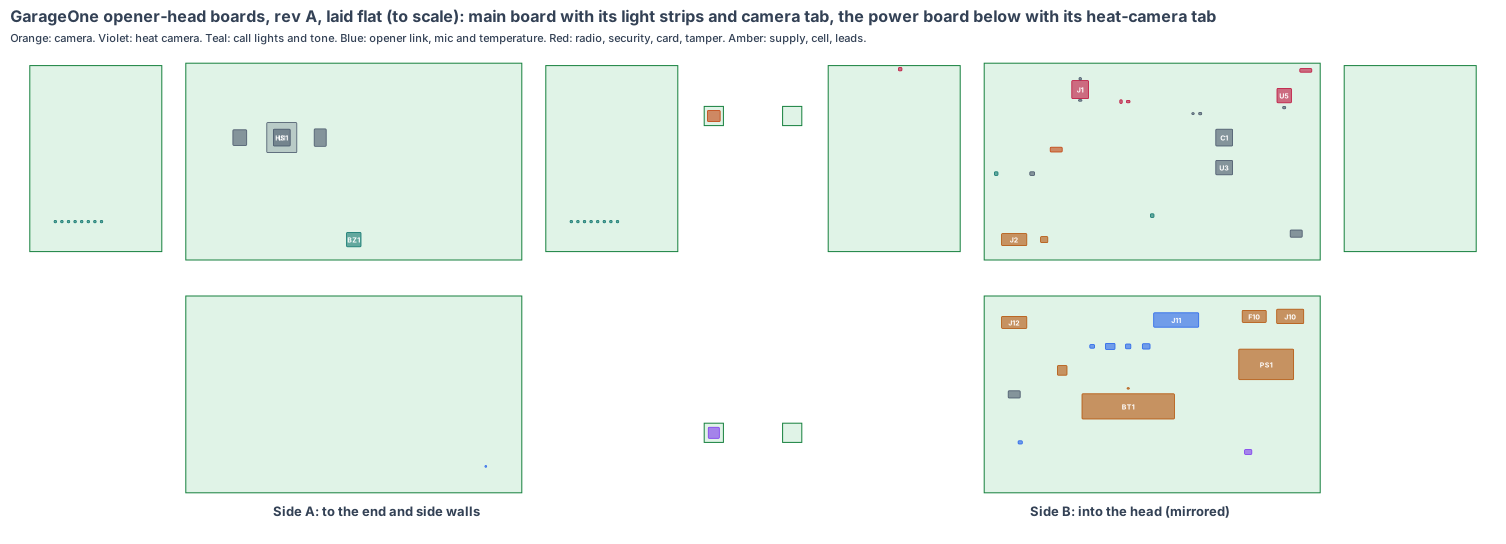
- The shape: the head is the same 300 × 460 × 180 mm opener head, and the opener’s own motor, gearbox and UL 325 logic board stay in its middle bay. So our boards fill the two end bays: an 8-layer main board (280 × 164 mm) stands 20 mm behind the door-end wall with the processor and the camera tab at the door window, and folds out into two 2-layer light strips (110 × 155 mm) on the side walls behind the call-light slots. A 4-layer power board (280 × 164 mm) stands 14 mm in front of the back-end wall with the opener’s mains, the backup cell and the opener link, and its heat-camera tab at the back window.
- A fix in the same run (rev T CAD): the bench head had its mic and temperature vents in the right side wall of the back bay, out of reach of a board on the back wall. The vents now sit in the back-end wall, two rows right in front of the SHT45 and the mic port. Both bay walls get a 16 × 12 notch for lead L1, and a small boss under the cover holds the tamper magnet over the right light strip. Drawn in the CAD the same day.
- Made from the shared rules: MEMS clocks, the latched microSD card with our software on every board, conformal coating against garage condensation and road salt, a thermistor on the backup cell, the camera 147 mm from the processor, every line of sight under 82° from its wall, the antenna in the corner farthest from the opener’s steel.
The bench head stays the test rig until the boards arrive. GarageOne never drives the motor: it presses the same wall-button input the wall control does, and the opener’s own UL 325 board, reversal and safety eyes decide every move.
1. The shape: two boards, two strips, two tabs
| Piece | Size | Layers | Where | What |
|---|---|---|---|---|
| Main board | 280 × 164 mm, 1.6 mm | 8 | standing 20 mm behind the door-end wall | the V1 core, card, security, Wi-Fi/BT and chip antenna, piezo, lead header |
| Door camera tab | 16 × 16 mm, 0.8 mm, on a 40 mm flex hinge | 4 | on its axis, 25° down, the lens just inside the 30 × 30 door window | IMX415 under a 102° M12 lens |
| Light strips (2) | 110 × 155 mm, 1.6 mm, on short flex folds from the main board’s ends | 2 | 3 mm inside each side wall of the door bay | 8 call-light LEDs each behind the 60 × 14 slot; the cover Hall chip on the right strip |
| Power board | 280 × 164 mm, 1.6 mm | 4 | standing 14 mm in front of the back-end wall | mains terminal, fuse, IRM-10-5, backup cell and charger, opener terminal, relay, optocoupler, ADC and I/O, mic, temperature chip, lead header |
| Heat camera tab | 16 × 16 mm, 0.8 mm, on a 40 mm flex hinge | 4 | on its axis, 40° down, just inside the 30 × 30 HDPE back window | MLX90640 |
Lead L1 (power board to main board: 5 V on two pairs, I²C, the mic’s I²S) is about 0.6 m of 22 AWG with Molex Micro-Fit 3.0 10-pin latched ends, clipped along the right side wall through the two bay-wall notches. Lead L2 (about 0.35 m) joins the power board’s opener terminal to the opener’s own logic board in the middle bay and is wired by the opener maker. The mains tap from the opener’s own mains terminal stays inside the head.
2. What is on the boards
Main board, side A (to the door-end wall): RV1126B (U1) under a 25 × 25 × 12 finned heat sink (HS1) with 6 mm of air to the wall; LPDDR4X (U2), eMMC (U11); the piezo (BZ1) over the tone holes, sealed to them by a foam ring; the door camera tab (U200, IMX415 under a 102° M12 lens, 25° down through the 30 × 30 window) held on its axis by a printed bracket.
Main board, side B (into the door bay): decoupling field (C1), power (U3), 24 MHz and 32 kHz MEMS oscillators (Y1, Y2), ATECC608B (U8), ID chip (U9), the latched microSD (J1, reached by taking off the cover), AP6256 (U5) with its chip antenna (ANT1) at the top left corner, camera supplies (U21), ESD array (U25), LED level shifter (U62), piezo driver (U63), eFuse (U42), lead header (J2), factory pads (TP1).
Light strips, side A (to the side walls): 8 WS2812B-2020 LEDs each (DL1–DL8, DR1–DR8) behind the opal side slots: green, amber, red and the white flash of the close warning. Right strip, side B: the TMAG5273 Hall chip (U7) at the top edge, 12 mm from the magnet in the cover boss.
Power board, side A (to the back-end wall): the SHT45 (U31) on an island cut free by a slot, behind the lower row of vents; the heat camera tab (U240, MLX90640, 40° down through the back window) on its printed bracket.
Power board, side B (into the back bay): spring-clamp terminal for the opener’s mains tap (J10) behind a printed shield, fuse and varistor (F10), IRM-10-5 (PS1), the 18650 holder and cell (BT1) with its thermistor (RT1), the charger (U50); the 5-pole opener terminal (J11), the photo-MOS relay across the wall-button pair (U70), the door-position optocoupler (U71), the ADS1115 ADC and TCA9534 I/O expander (U72), input guard (U73); the ICS-43434 bottom-port mic (U32) over a board hole behind the upper row of vents; heat camera supply (U23), lead header (J12), factory pads (TP2).
3. Every connection, checked
Every mating pair is checked against the makers’ documents, never “same as” another board.
| Pair | Check | Status |
|---|---|---|
| Micro-Fit 3.0 43045-1012 headers and the L1 lead | positive latch, 10 circuits, 5 A per contact against 1.2 A peak | to read the Molex drawing |
| Opener terminal and the opener’s logic board | wall-button pair, door-position output and backup battery as the opener maker documents them; the photo-MOS relay rated above the wall-button voltage | with the opener maker |
| Mains tap and J10 | WAGO 2604 class terminal for 18 AWG; class II creepage to the opener terminal | in the layout |
| IMX415 on its flex | 4-lane MIPI over the 40 mm hinge, impedance-controlled | in the routing |
| microSD socket | hinged, latched lid (lesson: sdcard) | pass |
4. Heat
About 1.5 W from the RV1126B goes through the finned heat sink into the door bay’s air (12 K/W est.), so the chip sits near 68 °C on a summer day with 45 °C at the garage ceiling and the head 5 K warmer inside. The camera chip is 147 mm from the processor, and the SHT45 is 222 mm from the supply on a slotted island so the freezing call reads the garage, not the board.
5. Power budget (est.)
| State | Draw |
|---|---|
| Watching: door camera at 2 fps (5 fps when something moves), heat chip at 2 Hz, mic listening, Wi-Fi | 2.4 W |
| A close warning: 16 LEDs flashing, the tone, the cell charging at 0.5 A | up to 5.5 W, 55 % of the 10 W supply |
| Power cut: camera at 1 fps, heat chip once a minute, alarm listener on | about 1.0 W, about 7 h on an aged, cold cell |
6. Factory test (every board, every time)
Spring-pin fixture on TP1 and TP2: 5 V in, the eFuse trip at 3.5 A, every rail, boot from the card, a frame of a test chart from the camera, a hot plate seen by the heat chip, a test tone into the mic, the SHT45 against a reference, all 16 LEDs, the piezo, the Hall chip with a magnet, the relay contact closing, the position input, a test voltage on the battery input, the security chip’s key, the Wi-Fi and BLE links.
7. Who makes what
One maker makes the main board with its tab and light strips, the power board with its tab, assembles them (turnkey) and makes lead L1 to length. We supply the microSD cards with our software and the lens focused at 4 m (est.). The opener maker fits our boards into the head, wires the mains tap and lead L2 to its own board, and re-lists the opener under UL 325. The quote pack is /build/garageone-quote.
8. Cost per head, electronics (est.)
| Item | Cost |
|---|---|
| V1 core (RV1126B, 2 GB LPDDR4X, 16 GB eMMC, power, AP6256, chip antenna) | $32 |
| IMX415 camera chip, holder and lens | $14 |
| MLX90640 heat chip | $45 |
| SHT45, mic, ADC and I/O | $6 |
| Photo-MOS relay, optocoupler, opener terminal | $3 |
| IRM-10-5, mains terminal, fuse, cell, charger | $14 |
| LEDs, piezo, Hall, security, ID, socket, passives | $7 |
| Boards (8-layer main with a tab and two strips, 4-layer power with a tab), 1,000 heads | $28 |
| Lead L1 | $2 |
| Assembly and test | $12 |
| microSD card with our software | $4 |
| Total | about $167 per head (est.) |
The bench head’s bought boards cost about $198 at qty 1 (Pi Zero 2 W, camera, MLX90640 board, mic and ADC, SHT45, ATECC608, NeoPixels, supply, cell and small parts), so our boards are about $31 cheaper per head at 1,000 (est.). The heat chip is over a quarter of the cost; a cheaper 16 × 12 chip is checked against the pan call on rev A.
9. Timeline
| Step | When |
|---|---|
| Shape and placement (this page) | done, 4 Nov 2026 |
| Rev T CAD: the boards in the head CAD, every part checked in 3D; the vents, lead notches and magnet boss already drawn | next |
| Schematic, footprints, routing | Dec 2026 – Jan 2027 |
| Rev A boards made and tested | Mar 2027 (est.) |
10. Still to check
- Wi-Fi from the head at the far end of a two-car garage, with the opener’s steel motor frame and rail 125 mm from the antenna.
- The opener link with each opener maker’s wall-button input (some use a serial wall control, not a plain button pair).
- The SHT45 reading against a reference in a cold chamber, with the supply and charger running.
- The heat chip on a wet pan at 3 m, and whether a cheaper 16 × 12 chip still sees it.
- The rev T CAD changes still to draw: the heat sink, the tab brackets, the board stand-offs and the printed shield over the mains terminal.
Sources
- Rockchip RV1126B (Forlinx FET1126Bx-S): https://www.forlinx.net/product/rockchip-rv1126b-som-fet1126b-bj-s-174.html
- Sony IMX415 (8.46 MP, 4-lane MIPI): https://www.sony-semicon.com/en/products/is/security/security.html
- Melexis MLX90640: https://www.melexis.com/en/product/MLX90640/Far-Infrared-Thermal-Sensor-Array
- Sensirion SHT45: https://sensirion.com/products/catalog/SHT45
- TDK InvenSense ICS-43434: https://invensense.tdk.com/products/ics-43434/
- TI TMAG5273: https://www.ti.com/product/TMAG5273
- TI ADS1115: https://www.ti.com/product/ADS1115
- Panasonic AQY212 PhotoMOS: https://industry.panasonic.com/global/en/products/control/relay/photomos
- Mean Well IRM-10: https://www.meanwell.com/Upload/PDF/IRM-10/IRM-10-SPEC.PDF
- Microchip ATECC608B: https://www.microchip.com/en-us/product/atecc608b
- Samsung INR18650-35E: https://www.samsungsdi.com/
- 16 CFR 1211 (UL 325 for residential garage door operators): https://www.ecfr.gov/current/title-16/chapter-II/subchapter-B/part-1211
- The head: products/garageone/cad/garageone-cad.mjs (rev A, vents, lead notches and magnet boss rev T); the boards: products/garageone/hardware/pcb/garageone-board.mjs
Design review (4 Nov 2026)
Every board is checked by the same rules (products/_shared/board-rules.mjs), one for each lesson any of our boards has taught us. GarageOne’s boards were made with every rule from the start: 18 pass, 4 fixed, 11 to prove, 0 fail. The full review, with every number and its source, is on the board page. It shows:
- Camera pixels: a 0.3 m parcel on the driveway 3 m past the open door (6.7 m away) fills about 97 px against a 20 px need; a small child at the far end of the doorway (4.7 m) about 115 px; the 8 MP chip at 5 fps uses 12 % of its link. The heat chip puts about 1.7 px on a 0.3 m wet patch in the heater pan at 3 m.
- What we learned about the heat camera: the water heater’s relief pipe (about 20 mm) is under one heat pixel at 3 m, so the drip call reads the water landing in the pan, not the pipe. It stays an assist call.
- Every garage call in view: both ends of the door’s bottom edge and its top section, a child and an adult in the doorway, the roof and bonnet of the two cars, the driveway 3 m out, someone by the side wall (44° across, the worst); the heater pan and relief pipe and the back of the bay, from where each lens or chip really sits.
- The vents moved (fixed): to the back-end wall, in front of the temperature chip and the mic port; lead notches and the magnet boss drawn in the CAD the same day.
- The opener stays in charge: one isolated relay presses the wall-button input after our 5 s light and tone warning; a board fault leaves it open.
- The latched microSD (J1) is fitted, and our software starts from it; updates run only with the door closed and no one in the garage.
- Fast lines on a solid ground plane (to prove, lesson: planes, from the CricketOne test-board layout of 4 Nov 2026): RV1126B memory; 1 camera MIPI link (100 Ω pairs); USB (90 Ω); antenna feed (50 Ω, keep-out on every layer); card lines (length-matched, no vias under the socket). Ground on the layer next to the parts (inner layer 1, supply on inner layer 2; the whole bottom of a 2-layer section), one via beside each ground and supply pad and none in pads, no copper or vias in the antenna keep-out on any layer or under the card socket, the impedance lines routed first with a test coupon. The quote asks for it; the routed board’s design rule check proves it.
- To prove on rev A: the AI time, the power-cut run on the cell, the SHT45 against a reference, Wi-Fi near the opener’s steel, the tab brackets, the mains creepage, the tamper magnet, the leads and the boards in the rev T CAD.
The request for quote is /build/garageone-quote.
New shared rule (4 Nov 2026, from the CricketOne test-board circuit): the Wi-Fi module’s own clock. Drawing CricketOne’s circuit pin by pin found that the AP6256 Wi-Fi/Bluetooth module runs from a 37.4 MHz reference clock, which our board notes had as 26 MHz or left out. Every board with an AP6256 is now checked for a 37.4 MHz clock beside it (MEMS where the product takes knocks). On this board the AP6256 had no clock of its own on the board; Y3, a 37.4 MHz MEMS oscillator, now sits next to it on side B. The review shows it under Radio (lesson: wificlock).