DiamondOne: one circuit board of our own in the plate, one in each base
The home plate and the three bases are the product. Each now carries one board of our own with every chip soldered on it, in the shape of the item it sits in. The bench build used a Raspberry Pi Zero 2 W, a Raspberry Pi AI Camera, a OmniPreSense OPS243-A radar module, three Seeed XIAO ESP32-S3 Sense boards and Adafruit power and light boards; none of them stays. There are no plugs, ribbons or adapters inside, only latched leads to the charge sockets.
| Board | Core (products/PCB-PLATFORM.md) | Where |
|---|---|---|
| Plate board | V1 (RV1126B) + two C1 camera chips + a 60 GHz radar chip | flat in the cast plate tub, 40 mm under the top |
| Base board (×3) | S1 (ESP32-S3 module) + one C1 camera chip | flat in each base tray, 4 mm over the floor |
Every number marked est. is measured on the first boards (rev A).
1. The shape
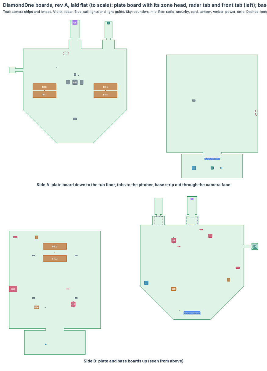
Plate board. An 8-layer board cut to the plate’s five-sided shape (340 × 339 mm), side A down to the tub floor, side B up to the top. Three pieces bend off it:
- Zone head: a 20 × 20 mm head on a 10 mm flex tail (about 200 mm, est.), held on a printed post up in the Ø34 window well. Its OV9281 camera chip looks straight up the strike zone; the lens front is 0.5 mm under the window cover.
- Radar tab: 32 × 59 mm, bent up and back from a tongue at the front edge so its face looks 30° up at the pitcher. The TI IWR6843AOP 60 GHz radar chip sits on it, its top end up in the radome well.
- Front tab: 24 × 54 mm, bent the same way from a second tongue. Its OV9281 camera chip looks 30° up at the pitcher, with the lens front 7 mm under the ground in the front window well.
Base board. A 4-layer 300 × 320 mm board flat over the tray floor, and a 200 × 79 mm front strip bent 90° up behind the camera face (side A out, 10 mm behind the face).
2. What is on the boards
| Plate board | Part |
|---|---|
| U1 | Rockchip RV1126B on side A, a copper heat block down to a cast boss on the tub floor |
| U10, U5, U3 | 2 GB LPDDR4X, 32 GB eMMC, PMIC |
| Y1, Y2 | MEMS oscillators (no quartz: the plate takes ball strikes and slides) |
| U6, AE1 | AMPAK AP6256 Wi-Fi 5 + BT 5, chip antenna under the radome well |
| U2, U9, J2 | ATECC608B security chip, ID chip, latched microSD with our software |
| BT1–BT4, RT1–RT2, U4, J1 | four soldered 18650 holders (1S4P), thermistors, BQ24074 1.5 A charger, latched lead to the sealed M8 charge socket |
| D1–D8, LP1, LS1, SW1 | call-light LEDs under a printed light guide, sounder under the tone holes, tamper switch |
| U11, L1 (zone head) | OV9281 1 MP global shutter, M12 2.1 mm lens, about 72° × 52° |
| U8, U12 (radar tab) | TI IWR6843AOP, its flash and MEMS clock |
| U13, L2 (front tab) | OV9281 1 MP global shutter, M6 lens, about 60° × 45° |
| Base board | Part |
|---|---|
| U21 | ESP32-S3-WROOM-1-N16R8, antenna end at the right edge |
| U22, U29, J22 | security chip, ID chip, latched microSD |
| BT21–BT22, RT21, U24, J21 | two soldered 18650 holders, thermistor, charger, latched charge lead |
| PD21–PD24 | solder pads for the four foot sensors’ tails, each with a strain-relief slot |
| SW21 | tamper switch under a post on the tray lid |
| U23, L3 (front strip) | OV2640 2 MP at SVGA 30 fps, M7 wide lens about 100° × 75° |
| MK21, LS21, D21–D28 | MEMS mic (the glove pop), sounder, call-light LEDs |
3. Every connection, checked
| Link | How | Checked |
|---|---|---|
| Both OV9281 chips to the RV1126B | 2-lane MIPI CSI-2 each, on the board and along the tab and tail flexes; one frame-sync line to both | lanes 1.23 Gbps of 1.6 (23 % spare) |
| Radar to the RV1126B | SPI and the radar’s own UART on the tab flex | TI IWR6843AOP reference design |
| Base camera to the ESP32-S3 | 8-bit camera port on the strip flex | ESP32-S3 camera interface, SVGA at 30 fps |
| Foot sensors | two pads each, a divider into an ADC pin, the tail soldered and clamped | Alpha MF02A FSR tails are solderable |
| Plate to bases | BLE LE Secure Connections, signed calls; each base times its frames and foot touches to the plate’s clock | 18 to 26 m |
| Charging | one latched Micro-Fit lead to a sealed M8 socket under a rubber cap (plate in the tub wall, base in the tray’s back face) | the only connector on each board |
4. Heat
The RV1126B draws about 1.8 W in play (est.). Its heat block goes down to a 39 mm cast boss on the tub floor; the plate is 120 mm into the ground, where the soil stays near 30 °C on a summer day (est.), so the ground is the heat sink. About 49 °C at the chip in full sun (est.).
5. Power budget (est.)
| Item | Plate | Base |
|---|---|---|
| In play | 3.0 W (RV1126B, two cameras at 120 fps, radar, Wi-Fi, BLE) | 0.7 W (ESP32-S3, OV2640 at 30 fps, BLE, foot sensors) |
| Between games | 0.3 W | 0.15 W |
| Cells | 4 × 18650 | 2 × 18650 |
| Worst-case day (aged to 80 %, 5 °C) | about 12.4 h for a 10 h tournament day | about 26 h |
6. Factory test (every board, every time)
Spring-pin fixture on the factory pads (no factory connector): rails and current, boot from the card, both camera chips streaming at 120 fps with the sync line, the radar’s self-test, the light, the tone, the tamper switch, the security chip, a BLE link to a test base; on the base board the camera, mic, four foot-sensor inputs and the charger.
7. Who makes what
One rigid-flex maker builds and assembles both boards (the plate board has three bent pieces; the base board one). Underfill under the RV1126B, memory, eMMC and radar chip; conformal coating with the sensors, sockets and antennas masked.
8. Cost per set, electronics (est.)
About $105 for the plate board and $32 for each base board at 1,000 sets (est., from the core boards in products/PCB-PLATFORM.md section 5): about $201 a set, against $1,990 for the set.
9. Timeline
Shape and placement are done (4 Nov 2026). Schematic, footprints and routing follow the CricketOne board; rev A after CricketOne’s rev A.
10. Still to check
- The rev T plate CAD: radome and front window wells run out to the front bevel under flush clear PC skins, the heat boss, the tamper post, the zone-head post.
- The radar’s pitch speed against a reference gun (it reads from about 2.5 m in).
- The base window opened to Ø16 with a chamfer for the wide lens.
- Wi-Fi and BLE from the flush plate through the radome skin.
Sources
- Official Baseball Rules 2.02 and 2.03
- OmniVision OV9281
- TI IWR6843AOP
- Rockchip RV1126B module (Forlinx FET1126Bx-S)
- Espressif ESP32-S3-WROOM-1
- Samsung INR18650-35E
Design review (4 Nov 2026)
New shared rule (4 Nov 2026, from the CricketOne test-board circuit): every cell pack has its own protector. CricketOne’s circuit puts a protector chip and two FETs on its cells, because the charger only stops charging: a short, too much current or a flat pack needs its own cut-off, at the thresholds of the cells’ chemistry (lesson cellguard, checked by the shared review: one protector for each charger, or a protected cell). The plate’s four-cell pack (U4) and the base’s two-cell pack (U24) had chargers and no protector: both power blocks now carry a TI BQ2970 protector and a dual FET (Samsung 35E cells have none of their own; zones est.).
Every board is checked by the same rules (products/_shared/board-rules.mjs), one for each lesson any of our boards has taught us. DiamondOne’s boards were made with every rule from the start: 29 pass, 4 fixed, 10 to prove, 0 fail. The full review, with every number and its source, is on the board page. It shows:
- Cameras: the ball at the top of a tall batter’s zone is 75 px across on the zone camera and 41 px at 2 m on the front camera; both OV9281 chips run their standard 120 fps mode with the global shutter, on one frame-sync line.
- Views: every plate call (zone corners for batters 1.50 to 1.87 m, the pitch 1 and 2 m out, the ball off the bat) and every base call is in view from where the chips sit, and every ray passes over the plate’s front edge.
- Window (lesson): in rev O the plate’s windows were holes in the middle of the 20 mm top, so a ray 15° up from 7 to 10 mm under the ground hit the top before leaving it. The radome and front window wells now run out to the front bevel under flush clear PC skins (rev T CAD; the skin is tested against spikes and a ball on rev A).
- Radar: flush in the ground it reads the pitch from about 2.5 m in, not at release; the release speed is worked back with the drag model and measured against a reference gun.
- Clocks and card: MEMS oscillators from the start, a latched microSD on both boards.
- Battery: the plate’s four cells give about 12.4 h for a 10-hour tournament day with cells aged and cold (24 % spare); each base’s two cells about 26 h.
- Fast lines on a solid ground plane (to prove, lesson: planes, from the CricketOne test-board layout of 4 Nov 2026): RV1126B memory; 4 camera MIPI links (100 Ω pairs); USB (90 Ω); antenna feed (50 Ω, keep-out on every layer); card lines (length-matched, no vias under the socket). Ground on the layer next to the parts (inner layer 1, supply on inner layer 2; the whole bottom of a 2-layer section), one via beside each ground and supply pad and none in pads, no copper or vias in the antenna keep-out on any layer or under the card socket, the impedance lines routed first with a test coupon. The quote asks for it; the routed board’s design rule check proves it.
The request for quote is /build/diamondone-quote.