CricketOne: rev Q (31 Oct 2026), owner review: a real wooden stump, nothing underground, no band; the first stump ordered; rev R: LED-style look, soft case, chip and camera first
IEMI’s ONE product for cricket (FLAGSHIP-PLAN F1, redesign R1). Rev A (27 Oct 2026) was a boundary mast with seven add-on modules. Under the smart-equipment rule (products/EQUIPMENT-SCHEMA.md) the product is now the wicket itself: three stumps and two bails at each end, at the size MCC Law 8 sets, with every part inside the stumps. A club swaps its stumps for ours and changes nothing else. The one detachable part is the umpire band. Name, slug and folds are kept.
Rev S (1 Nov 2026): the simple-to-make stump
Owner, 1 Nov 2026: “G10 is costing us more… we also need to drill… look for a more viable design which is easier for production builds… make sure the quality… bring the cost to around 100 +/- 50 dollars… simple to manufacture, reliable and easy to maintain.”
The CAD is build/cad-s/cricketone-s-cad.mjs; rev R stays in build/cad/ for its maker files and history. All of rev R’s checks run on rev S and pass: fit, clashes, bore, sleeve squeeze, keys, tamper, heat bar, Law 8 height. The assembly has no collisions.
| Rev R | Rev S | |
|---|---|---|
| Wall | G-10 tube, $160.94, 651 mm. Five cuts: notch, camera hole, light slots, lead hole, screw hole | Plain glass-fibre tube (pultruded, or filament-wound if R3 says so), 591 mm, cut to length by the supplier. One Ø6.5 hole at the back, 9.5 mm below the top, for the head’s spring button (R43) |
| Top | 75 mm cap: O-ring, screw through the tube | 135 mm sensor head, 120 mm above the tube. It holds the camera (bracket printed in), behind a clear polycarbonate disc on a ledge; the two call-light sticks behind clear strips at ±x; and the bail Hall sensors. A V-spring button holds it: press and lift. One 6-pin plug and the camera ribbon join it to the core |
| Camera height | z 617.6 | z 662 (R42: about 7 % finer along the pitch; 5-6 cm more blind ground at the stump foot, the popping crease stays in view) |
| Base | O-ring plug | Bonded with epoxy at the factory (two glue grooves). Two charge pads in the shoulder for a charging cradle; two spring pins meet pads on the cell carrier, so the core lifts out with nothing to unplug |
| Charging | Lead through the tube wall | Stand the stump in the cradle |
| Cells | 3 | 2 (the third bay is optional for long days) |
| Look | Paint, vinyl stripes, 2K clear | Printed vinyl wrap only |
| Inside | Soft TPU sleeves, slide-out core on a Kevlar cord | Same; the Pi and its heat bar sit 25 mm lower so the core ends under the head |
What we found while drawing it:
- A removable head needs one positive lock. A no-hole twist-lock ring glued inside the tube would leave too small an opening for the 30.6 mm core to pass. So the head uses a V-spring button through one hole: one drilled hole against five cuts and a screw.
- The head’s spigot wall is 1.1 mm, too thin for an O-ring groove: the first run split the head in two. The spigot is now a snug fit with no O-ring, and a 3 mm solid step joins it to the head.
Parts (all fit a 256 mm desktop printer or any SLS bureau):
| Part | Size (mm) | Material |
|---|---|---|
| Head | 134.7 × 38 × 38 | PA12, white |
| Base | 133 × 38.1 × 38.1 | PA12-GF, black |
| Cell carrier | 218.5 × 30.6 × 30.4 | PA12 |
| Middle carrier | 182.5 × 30.6 × 30.6 | PA12 |
| Top carrier | 159 × 30.6 × 30.6 | PA12 |
| Sleeves × 3 | up to 209.6 × 30.6 | TPU 95A, black |
| Bail × 3 | 109.5 × 18 × 15 | PA12, blue |
One stump is 259 cm³ of print.
Cost per smart stump at about 100 stumps (est.):
| Item | $ |
|---|---|
| Tube | 8 |
| Prints (PA12) | 30 |
| Radxa ZERO 3W | 30 |
| Camera module | 20 |
| 2 cells | 20 |
| Power, sensors, lights | 20 |
| Wiring, wrap, spike, fasteners | 15 |
| Total | about $143 |
That is inside the owner’s $100 ± $50. Injection-moulded parts and our own board bring it toward $100 later.
Quality gates:
- Row R3 drop- and ball-tests the plain tube before it is chosen.
- Every stump passes a 5-minute end-of-line test before it ships: camera, lights, bails, charge.
Seal, power and the product page (1 Nov 2026, owner): “make sure all these designs are aligned with our hardware, Pi, Radxa, camera and batteries… how we are planning to attach batteries to the Pi / Radxa… secure to heat, water… navigate to all these design changes in the same product page.”
-
Water.
- The first rev S head had no seal, and its button hole was open to the core. Since the camera and lights live in the head, only the ribbon and one plug pass the spigot, so its bore is now r 11 and its 4.7 mm wall carries rev R’s 28 × 1.5 NBR O-ring at z 575, below the button. The spring sits in a back pocket above the O-ring. The top carrier’s key moves in to x -12.2 so its notch never cuts the groove.
- The base is bonded; the Hall sensors, charge pads and pins are potted; the window and strips are glued.
- An adhesive ePTFE vent over a Ø3 hole in the head lets the sealed stump breathe.
- Boards are conformal-coated.
-
Power.
- The old path (a non-locking JST-PH plug, a 1 A MiniBoost, boards on foam tape, a charge lead through the wall) is replaced. The empty third cell bay now holds the TP5000 charger (3.6 V), a 3 A fuse on the pack + and a locking Molex Micro-Fit 2-pin plug: the cell carrier is a self-contained pack.
- The middle carrier carries the Micro-Fit receptacle, the INA219, a Pololu U3V40F5 5 V boost (about 2.5 A at 3.2 V, est., enough for the Radxa plus lights) and a locking JST-GH 6-pin plug (5 V and GND on two pins each, plus I²C) up to the top carrier.
- The Pi or Radxa is soldered to 5 V pins 2 and 4 and GND 6 and 9. Every lead is tied to its carrier within 15 mm of each joint.
- All parts are drawn in the CAD and fit-checked; every check passes.
-
Heatsinks (owner: check the ones ordered fit).
- The Geekworm C296 (64 × 29 × 10, for the Pi) cuts the bore by 1,612 mm³ in the CAD, so it is for the bench only.
- The Radxa 5519A is a 55 × 19 × 2 mm copper plate (retailer sizes). To fit it under the heat bar, the bar’s back flat moves up 1.25 mm (y0 4.75; the bar is now 10.25 deep and 32.8 g, against 37.2 g).
- Radxa stack: chip, the plate’s own silicone sheet, the plate, paste (0.1 mm left).
- Pi stack: 1 mm pad, the C296 kit’s 0.8 mm copper shim, 0.5 mm pad.
- The R17 to R19 checks still pass: seats, cheeks, lugs, end screws, a 0.875 mm bore gap, and 17.8 % strip squeeze.
- The lighter bar holds a little less heat: R16’s soak is re-run when a board is measured.
-
Pi and Radxa. Both boards share the 65 × 30 footprint and four standoffs. The Radxa’s chip position under the heat bar and its height are checked on arrival.
-
Site. The product page’s “Stump CAD” section (
src/components/StumpBuild.astro) readsbuild/cad-sdirectly:- our printed parts on their own;
- the bought parts grouped by where they sit (from the fit check);
- the assembled stump;
- the power path;
- water and heat.
The first-stump page links to it instead of repeating it.
Round bails (1 Nov 2026, owner): “I don’t like our bail design, let’s re-design with standard size with rounded shapes… accurately per standard size / dimensions but not square”. The owner’s pictures are Zing-style LED bails. cad/bail-round.mjs replaces the block bail in both the product CAD and rev S:
- Lengths: Law 8.3, 109.5 overall, barrel 54, spigots 35 and 20.5.
- Barrel: round Ø22, with domed ends (r 4) and two raised rings Ø23. Hollow with a 1.4 mm wall, and two Ø3 drains.
- Spigots: round Ø9, with rounded tips and a 0.7 mm flat top and bottom, so the bail settles magnet-down.
- Rise: 10.8 mm above the stumps (Law: 12.7, which would allow up to Ø26.8).
- Mass: 10.7 g against 8.4 g for an ash bail (within ±40 %).
- Magnets: unchanged, the same places over the sensors.
All checks pass. A 2.0 mm wall made it 12.4 g, so the wall was thinned rather than the limit widened.
Still to do:
Re-run the camera-view simulations at the new height.Done in R42: the view is fine; the window disc became Ø16 on a 1.6 mm ledge, flush with the head.Size the spring button against a real one.Done in R43: a 1/4 in × 3/16 in single-end snap button on a 0.6 mm seat pad, the hole 9.55 mm below the tube top (was 5.55) in an 18 mm spigot, opened with a 5 mm hex key.Draw the charging cradle.Done in R44: a printed cradle for three stumps, spring pins on the pads, and a key groove in the base so a stump only stands in one way.The R4 maker files move to rev S: tube, one hole.Done in R45:build/cad-s/step/(tube, head, base and bail STEP; tube and clear parts DXF); the wrap needs a Ø8 hole over the button.
Rev R (31 Oct 2026): the look, the soft case, printed bails, makers, chip and camera first
The owner asked for four changes:
- stumps and bails like their reference picture (LED-style: blue stumps, white tops, square bails with a grey window);
- every inside part in a soft case that can be pulled out and pushed back for battery changes and maintenance;
- makers who can build our glass-epoxy walls, with our help on the CAD;
- a cheaper shell IEMI Labs can make itself.
They also split the order: the chip and camera first, so programming starts now.
Full write-up: build/SHELL.md (https://iemilabs.com/build/cricketone-shell).
-
Look:
- the stump wall is blue with cyan stripes and “IEMI · CRICKETONE”;
- the printed cap is the white top;
- the outer stumps match.
-
Soft case:
- the carriers are cut down to Ø28.4, with Ø30.6 end flanges;
- three split TPU 95A sleeves clip on, and eight ribs touch the bore at 0.075 mm squeeze;
- a Ø2 Kevlar pull cord runs from the cell carrier’s anchor bar up the back channel to a loop under the cap, so the whole core comes out in one piece;
- the cap is held by one M3 screw into a heat-set insert, which closes the cap-retention risk.
The CAD checks the bore, the rib squeeze, the Pi slots, the cord path, clashes and keys on every run. Rev R’s new bore check found that the old Pi rails and the camera bracket reached past the bore; both are fixed.
-
Bails:
- printed block bails (cad/bail-block.mjs), Law 8.3 lengths, 10.5 mm above the stumps, 10.7 g (ash 8.4 g, est.);
- the magnets sit over the same sensors;
- the product CAD and the build CAD both use them now.
-
Makers:
- Xometry and Protolabs (CNC on G-10), The Gund Co (filament-wound, black);
- Xiangcheng Chengrui (blue epoxy-glass tube, minimum 1);
- Max-Gain (pultruded tube, the same 1.5 × 1/8 in).
We send each maker our machining drawing and CAD.
-
Production shell: a glass-fibre tube stays the structure, since poured urethane alone is about 10 times too floppy. The lab route is:
- a pultruded tube cut to length;
- a printed drilling jig;
- paint and vinyl under a 2K clear coat;
- cast white tops from a silicone mould;
- later, an overmoulded blue skin.
That is about $10-13 a stump (est.), against $160.94 for one G-10 tube. The risk is that pultruded tube can split lengthwise on a point impact (est.), so row R3 drop-tests it against G-10 first.
-
Law: this replaces rev Q’s “production stumps are wooden ash”.
- MCC Law 8.1 describes wooden stumps.
- ICC playing conditions allow approved LED wickets, and leagues can do the same.
So glass-fibre CricketOne stumps are for training, nets and leagues that approve them, as LED stumps are today.
-
Pi and Radxa bake-off (1 Nov 2026, owner decision: “try both and take one to production for now”):
-
The Radxa ZERO 3W was ordered alongside the Pi, each with one of the pack’s two OV9281 cameras.
-
Rev R’s glass-fibre tube takes a 30 mm board, so the old reason against the Radxa (the 22 mm ash bore of Q9-Q10) no longer holds.
-
Our camera setup for it (software/radxa/) combines two of Radxa’s own overlays, with the power pin held on, so no driver patch is needed.
-
build/BRINGUP.md section 5 picks the board for the first stump by:
- camera reliability;
- raw frame rate;
- frame rate with the clip running;
- pose rate;
- secure boot;
- heat;
- price.
If both pass 1-3, the Radxa goes in.
-
pair_test.pymeasures the two-board link and clock agreement. -
Our RV1126B board, or a ready-made module, stays the later production step.
-
-
Stump computer (1 Nov 2026, owner question): the product CAD, site and parts list still named the Radxa ZERO 3W from rev P. They now show what Q7 decided:
- the first build and the bench use the Raspberry Pi Zero 2 W;
- production uses our own 22 mm RV1126B board (Q10);
- the Radxa ZERO 3W is dropped and no longer on any list.
-
Order: order 1 is the Pi Zero 2 W (2), the OV9281 camera, ribbons, microSD cards, leads and headers ($278.33 on Amazon). Order 2 waits for rev R; FIRST-STUMP.md section 7 lists its changes.
R110. The 13-number fit on the Pi Zero 2 W (2 Nov 2026, rev S row R110; software/track2d.py, sim/track-sim.mjs, sim/fittime-r110.mjs)
Why this row. R109 made the flight fit follow the swing’s change (13 numbers) and added the drift to the call’s sigma. Both cost time on the brain, and the call has to be on the stumps’ lights and in the app within 1 s of the ball reaching the stumps. We asked how long the fit and its sigma take per ball on the Pi Zero 2 W’s four 1 GHz Cortex-A53 cores, and what to trim if it is too slow, without moving the calls.
How we checked it. sim/fittime-r110.mjs, 9 of 9 checks, on the same 100 deliveries as R105 to R109 (R109’s design: 13 numbers, drift term). sim/track-sim.mjs gains SIM_COUNT (flight steps, residual calls, iterations and time for every ball), SIM_FIT_DT (the fit’s flight step), SIM_STOP (stop once a step cuts the squared residual by less than that share) and SIM_ITMAX; with none set every earlier result is unchanged (R109’s design repeats exactly). Times on this PC (Core i7-1185G7, one case at a time) are scaled x15 for the Pi’s cores (est., the same factor as R86), with the Jacobian columns (86 % of the fit’s work) and the sigma terms shared over 3 cores; the fourth keeps the cameras running. The budget: 1 s less 0.1 s waiting for the far end’s last part (R106) and 0.1 s for the lights and the radio (est.) leaves 800 ms for the fit and its sigma. About 213 points a ball (median).
| Case (simulated, 100 deliveries) | Iterations, median / worst | Flight steps a ball (median) | This PC, median / worst | Pi Zero 2 W (est.), median / p95 / worst | Biggest call move vs R109, line / height; sure flips | Sure calls outside own 2 sigma |
|---|---|---|---|---|---|---|
| R109 design (0.5 ms step, run until no step improves) | 14 / 25 | 242,385 | 178.7 / 574.1 ms | 1114 / 1667 / 3489 ms | - | 2 of 48 |
| 2 ms flight step | 14 / 25 | 60,169 | 51.3 / 91.9 ms | 316 / 513 / 607 ms | 0.08 / 0.25 mm, 0 flips | 2 of 48 |
| stop once a step gains under 0.01 % | 7 / 14 | 133,245 | 99.4 / 181.7 ms | 557 / 757 / 1068 ms | 0.15 / 0.37 mm, 0 flips | 2 of 48 |
| both (design) | 7 / 17 | 33,366 | 29.7 / 75.3 ms | 167 / 230 / 446 ms | 0.16 / 0.4 mm, 0 flips | 3 of 48 |
What we learned.
- As fitted in R109 the call would be late. The median ball needs about 1.1 s on the Pi (est.) and the worst 3.5 s, over the 0.8 s budget. Almost all the work is integrating the ball’s flight: 242,385 small steps a ball, because every one of the 13 Jacobian columns flies the whole track again at a 0.5 ms step, for up to 25 iterations.
- The flight step was far finer than it needs to be. A 2 ms step moves no call by more than 0.08 mm in line and 0.25 mm in height and flips no sure call, for 4 times less work.
- Half the iterations gained nothing. Stopping once a step cuts the squared residual by under 0.01 % halves the median iterations (14 to 7) with no call moved more than 0.37 mm.
- Both together: 7.3 times less work. About 167 ms a ball on the Pi, 230 ms at p95 and 446 ms at worst (est.), inside 800 ms with room for the x15 factor to be off by 2x. The same 48 % sure calls, every sure call inside 25 mm (worst 7.7 / 18.5 mm), 3 of 48 outside their own 2 sigma (R109: 2), no call moved more than 0.4 mm.
What we designed.
track2d.FITgains the trims:step_s=0.002,stop_gain=1e-4,max_iter=25, and the budget (budget_ms=800, fromcall_s1 s lesswait_s0.1 s andshow_s0.1 s).track2d.fit_budget_ok(fit_ms, sigma_ms)checks a ball’s time; a ball over budget still gets its call, late, and is logged. Self-test_fittime_selftest().sim/track-sim.mjsgainsSIM_COUNT,SIM_FIT_DT,SIM_STOPandSIM_ITMAX.- No CAD, print, paint or part change. BRINGUP.md 4d step 28 times every ball on the Pi with the camera loop running.
Limits. The x15 PC-to-Pi factor and the 3-core share are estimates (est.); the real time comes from B1 on the Pi Zero 2 W (due 6 Nov). The fit in the sim is JavaScript; on the Pi it must be compiled code or numpy vectorised over the 13 columns, since a plain Python loop over 33 000 flight steps would be far slower. The 0.1 s for the lights and radio is est. Python was not run on this PC (no Python 3); the self-tests run on the Pi.
Sources (R110): Raspberry Pi Zero 2 W, quad Cortex-A53 at 1 GHz: https://www.raspberrypi.com/products/raspberry-pi-zero-2-w/ ; Arm Cortex-A53: https://developer.arm.com/Processors/Cortex-A53 ; Levenberg-Marquardt stopping rules: https://en.wikipedia.org/wiki/Levenberg%E2%80%93Marquardt_algorithm ; Runge-Kutta step error: https://en.wikipedia.org/wiki/Runge%E2%80%93Kutta_methods
R151. How often a wet day has the sun out (4 Nov 2026, rev S row R151; sim/wetsun-r151.mjs)
Why this row. R145-R150 ran each of the seven skies equally often at every ground, with rain odds by sky that we assumed (RAIN_P, est.), and found that a wet ball leans only with the sun out. That even mix gives the sun out 79 % of the day at all three grounds and rain on 25 % of days everywhere. This row checks those odds against the published climate records for the three grounds, and asks how many balls in a real season are wet and sunny at once, whether the told error must carry more, and which wet-ball bench steps (61-65) should come first.
How we checked it. sim/wetsun-r151.mjs, 6 of 6 checks. The climate records (1991-2020 normals) are real; everything else is simulated (est.), R148-R150’s match model and R147’s sized film unchanged. Sunshine share = recorded sunshine hours / (days x day length). Each sky’s own sunshine share over a day of play comes from the same sky model (direct sun over 0.15 of a clear sun, about the WMO 120 W/m² sunshine line, est.), and each ground’s sky mix is the least change from even (maximum entropy) that matches its record. Rain days become rain in play at 0.6 of a rain day (est.), and RAIN_P is scaled per ground to match. Dew odds (DEW_P) stay as assumed; no record gives them.
| Ground (record) | Sunshine: record / even mix | Rain in play, share of days: record / assumed | Wet balls with the sun out, per 1000: climate / assumed | Share of those from dew | Told error covers (2 sigma) |
|---|---|---|---|---|---|
| London, June (Kew: 209.8 h, 8.5 days of 1 mm or more) | 42 % / 79 % | 17.0 % / 24.7 % | 9.1 / 32.2 | 67 % | 100 % |
| Mumbai, November (Colaba 267 h; Santacruz 0.6 rain days) | 79 % / 79 % | 1.2 % / 24.7 % | 158 / 168.5 | 100 % | 96.9 % |
| Melbourne, January (Airport: 272.8 h, 61 %, 8.3 days of 0.2 mm or more) | 61 % / 79 % | 16.1 % / 24.7 % | 34.8 / 37.3 | 88 % | 98.0 % |
| Three seasons | 60 % / 78 % of balls | 67.3 / 79.3 | 96 % (85 % assumed) | 97.2 % (98.3 % assumed) |
Wet sunny balls p95 0.24 mm in the real seasons (0.21 with the assumed odds; 0.19 with the film known exactly); wet balls under cloud 0.03 mm. To cover 95 % of wet sunny balls the told error needs 0.118 mm (WET_TOLD_MM is 0.15). Every ball’s gloss error p99 goes 0.31 -> 0.26 mm, because London and Melbourne are cloudier than the even mix said.
What we learned.
- Our skies were too sunny for London and Melbourne. The even mix said 79 % sunshine; the records say 42 % in a London June and 61 % in a Melbourne January. Mumbai’s November matches (79 %).
- Our rain was too often, above all at Mumbai. A Mumbai November has 0.6 rain days by its record, so rain in play falls on about 1 % of days, not 25 %. London and Melbourne rain in play on about 16-17 % of days.
- Wet sunny balls are fewer, and nearly all dew. 67 in 1000 balls over the three seasons (79 assumed): London 9, Melbourne 35, Mumbai 158. 96 % of them are dew-wet (Mumbai 100 %): rain comes with cloud, dew comes in the evening under a low sun.
- The told error still carries it. WET_TOLD_MM 0.15 covers 97.2 % at 2 sigma (95 % needs 0.118 mm); Mumbai’s dew is the hardest case at 96.9 %. No constant changes.
- So the bench should start with dew, not soaking. The wet ball that matters is a lightly, evenly misted ball under a low sun, the Mumbai evening. Steps 61-62 come first, done with a misted ball at a low lamp angle; the soaked-ball steps 63-65 come after.
What we designed.
- No code, part, CAD or cart change. RAIN_P stays in the sims for comparison with R145-R150; the climate weighting lives in
sim/wetsun-r151.mjsfor later rows. - BRINGUP.md 4d step 66: do steps 61 and 62 first with a misted ball (a fine spray, no drips, as evening dew) at a lamp 10-30° above the bench, before the soaked ball of steps 63-65.
Limits. The sunshine and rain records are monthly means for the month of each match day, not for the hours of play; play hours are sunnier than the whole day. Mumbai’s sunshine is Colaba’s and its rain days Santacruz’s (IMD counts a rainy day at 2.5 mm). Melbourne counts rain days at 0.2 mm, so its rain is on the high side. The dew odds, the sky model and the share of a rain day in play are est.
Open questions. 1. How often does dew really wet the ball at each ground, and from what time (DEW_P is still assumed; next row R152)? 2. Is a misted ball’s film the same as dew’s at the bench (step 66)? 3. Do day-night matches under lights, where dew falls with no sun, need their own row?
Sources (R151): London, Kew Gardens 1991-2020 (Met Office normals, via https://en.wikipedia.org/wiki/Climate_of_London ; Met Office climate averages https://www.metoffice.gov.uk/research/climate/maps-and-data/uk-climate-averages ); Mumbai, Santacruz and Colaba (India Meteorological Department normals, via https://en.wikipedia.org/wiki/Mumbai#Climate ; IMD https://mausam.imd.gov.in/ ); Melbourne Airport 1991-2020 (Bureau of Meteorology, via https://en.wikipedia.org/wiki/Climate_of_Melbourne ; BoM climate averages https://www.bom.gov.au/climate/averages/ ); WMO sunshine duration (direct beam over 120 W/m²): https://community.wmo.int/en/activity-areas/imop/cimo-guide
R150. A wet seam’s own lean (4 Nov 2026, rev S row R150; sim/wetseam-r150.mjs)
Why this row. R146 left open whether water held in the seam’s stitches leans the ball differently from the leather. The seam is a raised band about 1 mm proud with six rows of stitches (Law 4) that turns with the spin (R128), so on a wet ball its wet side may glint on its own, off the film’s highlight and not where the lacquer’s sits. R149 found the wet highlight cannot size the film until the bench measures it, so this row asks the other wet-ball question that needs no bench: how much a wet seam adds at the stumps over R147’s sized film, whether it averages out over a delivery’s spin, and whether the told error still covers it.
How we checked it. sim/wetseam-r150.mjs, 6 of 6 checks, all simulated (est.), 68,922 balls on 126 days (60 wet), R148’s model and R147’s sizing unchanged. Added: where the seam passes within 35° (the steepest a raised seam side faces, est.) of the highlight’s point (half-way between the sun and the camera), its wet side glints at the seam’s nearest point, carrying 0.1-0.3 of the film’s highlight (0.1 more by 80 overs as the stitches stand prouder, est.). Each delivery spins: seam bowlers (65 %, est.) backspin at 8-20 rev/s about a level axis with the seam upright and a 3-30° wobble; spinners 20-40 rev/s about a random axis with the seam 15-75° to it. The finder’s 30 looks over a 0.45-0.65 s flight are averaged, as the track fit does (R128). Two stress cases: the seam held still for one look, and the glint at twice the share.
| Gloss error at the stumps, p95 (simulated, est.) | R147, dry seam (as R149) | R147, wet seam | wet seam held still (one look) | wet seam at twice the share | film known exactly, dry seam | film known exactly, wet seam |
|---|---|---|---|---|---|---|
| Every sunny ball | 0.19 | 0.19 | 0.19 | 0.19 | 0.18 | 0.18 |
| Dry | 0.18 | 0.18 | 0.18 | 0.18 | 0.18 | 0.18 |
| Wet | 0.26 | 0.25 | 0.25 | 0.25 | 0.21 | 0.20 |
| Wet, seam bowlers | 0.26 | 0.25 | 0.25 | 0.25 | 0.21 | 0.21 |
| Wet, spinners | 0.26 | 0.26 | 0.25 | 0.26 | 0.21 | 0.20 |
| Soaked (0.7+) | 0.28 | 0.27 | 0.27 | 0.27 | 0.24 | 0.25 |
| Dew at Mumbai | 0.24 | 0.23 | 0.23 | 0.23 | 0.18 | 0.19 |
| Worn ball wet, overs 40-79 | 0.21 | 0.20 | 0.21 | 0.20 | 0.14 | 0.14 |
Wet balls p99 0.47 mm with a dry seam and with a wet one (0.48 held still, 0.47 at twice the share). Sure LBW decisions moved 3.1 per 1000 in every mode; none firm and wrong in any mode.
What we learned.
- A wet seam leans the ball very little. On its own it moves the ball 0.007 mm median and 0.044 mm p95 at the stumps for seam bowlers, 0.002 and 0.021 mm for spinners. It is a share of the film’s highlight, which is itself only 0.1 mm median (R146), and it sits beside the highlight, not out at the edge of the ball.
- The spin averages it, more for spinners. Over a delivery’s 30 looks a spinner’s seam keeps 0.37 of one look’s p95: its tilted seam sweeps across the highlight both ways. A seamer’s keeps 0.64: an upright seam turns in its own plane and stays where it is through the flight, so only the wobble averages it.
- It does not add to what R147 leaves. Its direction turns with the seam, not with the sun, so it does not line up with the sun’s lean. Wet balls go 0.26 -> 0.25 mm p95 (the glint sits on average a little nearer the ball’s middle than the highlight, which trims 0.01 mm; too small and too uncertain to use), and held still or at twice the share they stay at 0.25.
- The told error still covers it. WET_TOLD_MM 0.15 at 2 sigma covers 97.0 % of wet balls with the film on (96.9 % with a dry seam, 97.0 % at twice the share). Nothing else moves: 2 window resets with all 126 new balls logged, R147’s no-sign switch on 9 overs, all wet, and dry balls untouched.
- So the wet-ball line now waits on the bench. What is left on wet balls (0.25 against 0.20 mm with the film known) is the film’s coat share, which R148-R149 found the stumps cannot learn yet; steps 61-65 measure it.
What we designed.
- track2d.py: a comment at the R147-R149 constants recording that a wet seam needs no term of its own and why (no new constant or code path).
- No part, CAD or cart change. BRINGUP.md 4d step 65: on step 63’s soaked worn ball, turn the ball in steps so the seam crosses the highlight, and log the lean at each step wet and dry.
Limits. All simulated (est.): the seam’s glint share, the steepest side of a raised seam, the spin rates, wobble and tilt, and the share of seam bowlers are assumed. The glint is modelled as a point at the seam’s nearest place to the highlight, not drawn pixel by pixel; a wet cream seam may also brighten its own diffuse look, which R135’s dry seam model already carries. Python was not run on this PC.
Open questions. 1. Does a soaked seam glint more than 0.3 of the film’s highlight at the bench (step 65)? 2. How often does a real wet day have the sun out at all (R149 question 3, next row R151)? 3. Does a scrambled seam (wobbled on purpose by the bowler) on a wet ball read like a spinner’s?
Sources (R150): the ball and its seam (Law 4, The ball): https://www.lords.org/mcc/the-laws-of-cricket/the-ball ; seam and spin in flight (Mehta, “An overview of cricket ball swing”, Sports Engineering 2005): https://doi.org/10.1007/BF02844004 ; why wet surfaces look glossier (Lekner and Dorf, Applied Optics 1988): https://doi.org/10.1364/AO.27.001278
R149. The film’s coat share from the wet highlight (4 Nov 2026, rev S row R149; sim/wetcoat-r149.mjs)
Why this row. R148 found that what is left on a wet ball is the water film’s coat share (0.25-0.75 of a lacquer coat by day, est.), not the day’s darkening. R146 described the film’s highlight as broader than lacquer’s and about half as bright. This row asks whether the stumps can read the coat share from that highlight in their own pictures, by its brightness or by its width, well enough to size the film each over or each day, without new false new balls.
How we checked it. sim/wetcoat-r149.mjs, 7 of 7 checks, all simulated (est.), 126 days (55 wet), R148’s model unchanged (the towel at intervals included). Each over with the sun out the cameras read two things: the highlight’s brightness (R144’s read: 0.25 of a new ball’s gloss an over and a day’s bias of 0.2, calibrated on the over count’s gloss over the last 8 dry sunny overs) and its width past the lens blur, which reads the water’s share of the highlight (0.15 an over and a day’s bias of 0.05, est.; lacquer is a point, water a broader patch), turned into a film with the count’s lacquer (known to 0.3 relative). 21 readers were swept (each read and the two averaged; the day’s coat share by least squares from 2, 4 or 8 wet overs in sun on R147’s wetness reading, or blended into R147’s size each over), plus a control: R147 with a larger or smaller WET_FULL and no highlight. The best of each is picked on these same days (so flattered), then checked by picking on half the days and scoring on the other half.
| Gloss error at the stumps, p95 (simulated, est.) | R146, one table on the sign | R147, sized from the fall (kept) | best brightness reader | best width reader | best of both | the film’s coat share known | film known exactly |
|---|---|---|---|---|---|---|---|
| Every sunny ball | 0.19 | 0.16 | 0.16 | 0.16 | 0.16 | 0.16 | 0.15 |
| Dry | 0.19 | 0.15 | 0.16 | 0.15 | 0.15 | 0.15 | 0.15 |
| Wet | 0.23 | 0.21 | 0.21 | 0.19 | 0.19 | 0.17 | 0.11 |
| Damp (under 0.4) | 0.13 | 0.11 | 0.12 | 0.10 | 0.11 | 0.10 | 0.07 |
| Soaked (0.7+) | 0.34 | 0.27 | 0.26 | 0.23 | 0.23 | 0.20 | 0.13 |
| Dew at Mumbai | 0.23 | 0.21 | 0.22 | 0.18 | 0.18 | 0.17 | 0.08 |
| Worn ball wet, overs 40-79 | 0.24 | 0.21 | 0.22 | 0.18 | 0.17 | 0.17 | 0.08 |
Picked on half the days and scored on the other half, the best reader of both gains 0.00 and 0.02 mm on wet balls (p95); the width alone -0.02 and 0.03; a plain larger WET_FULL -0.01 and 0.00. A plain WET_FULL 0.6 with no highlight gets 0.205 mm in sample. Sure LBW decisions moved 3.1 per 1000 in every mode; none firm and wrong in any mode.
What we learned.
- The brightness hardly reads the film. Correlation 0.022 on 269 wet overs in sun, error 0.175 median and 0.5 p95 of a coat. The highlight is under one pixel on a 2.8 px ball (R144), and calibrating on the dry overs takes out the day’s bias, not the over’s noise.
- The width reads it roughly. Correlation 0.387: the spread reads the water’s share of the highlight, a ratio, so the day’s brightness bias cancels. But turning a share into a film needs the lacquer, which the count knows to about 30 %, and on a worn ball the share is near 1, where the sum blows up (p95 error 1.279).
- No reader learns the day’s coat share. On their own days the learned share errs 0.302 (brightness), 0.25 (width), 0.166 (both) median against 0.158, 0.091, 0.112 for R147’s one 0.5. Only 365 wet overs had the sun out to read on; wet days are mostly cloudy.
- The gain is in sample only. The best reader (both reads averaged, the day’s share from 2 wet overs) takes wet balls 0.21 -> 0.19 mm and soaked balls 0.27 -> 0.23 on the days it was picked on, but on days it was not picked on it gains 0.00 and 0.02 mm, and a plain larger WET_FULL gets most of the in-sample gain. Not adopted: track2d.py keeps R147’s WetSize with a comment.
- What it would take. Re-run with the width read at 0.03-0.07 of the water’s share an over (not 0.15), the width follows the film at correlation 0.58-0.76, but the held-out gain is still mixed (one half better, one worse). The bench (step 64) measures the real width read; under about 0.05 it is worth a new row. Nothing else moves: 1 window reset with all 126 new balls logged, R147’s no-sign switch on 9 overs, all wet, and WET_TOLD_MM 0.15 still covers 99.7 % at 2 sigma.
What we designed.
- track2d.py: a comment at the R147/R148 constants recording that WET_FULL stays 0.5 and why (no new constant or code path).
- No part, CAD or cart change. BRINGUP.md 4d step 64: on step 63’s soaked worn ball at 20 m, log the highlight’s brightness and width on every look, wet and dry, three times.
Limits. All simulated (est.): the film’s share of a coat, the highlight’s brightness and width reads, the wet darkening, the spray odds and the rain and dew odds are assumed. The width is modelled as the water’s share of the highlight plus noise, not drawn pixel by pixel. Python was not run on this PC.
Open questions. 1. How steady is the highlight’s width at 20 m over 6 balls on a real wet ball (step 64)? 2. Does a wet seam (water held in the stitches) lean differently from the leather (R146 question 3, next row R150)? 3. Do real wet days have the sun out often enough for any highlight read to matter?
Sources (R149): why wet surfaces look darker and glossier (Lekner and Dorf, Applied Optics 1988): https://doi.org/10.1364/AO.27.001278 ; Fresnel reflection and water’s refractive index: https://en.wikipedia.org/wiki/Fresnel_equations ; drying a wet ball (Law 41, Unfair play): https://www.lords.org/mcc/the-laws-of-cricket/unfair-play
R148. The day’s own wet fall (4 Nov 2026, rev S row R148; sim/wetfall-r148.mjs)
Why this row. R147 reads how wet the ball is as the shine window’s fall over one WET_FALL (0.09), but a fully wet ball falls 6-12 % depending on the day (est.), which R147 named as the reading’s largest error. This row asks whether the stumps can learn the day’s own fall, from the soaked overs of a wet spell (spray seen off the bounce on several balls of one over) or from the rise when the umpire dries the ball at an interval, and whether that closes the gap to the film known exactly (0.24 against 0.19 mm in R147) without new false new balls.
How we checked it. sim/wetfall-r148.mjs, 6 of 6 checks, all simulated (est.), 68,934 balls on 126 days, 60 of them wet. R147’s model unchanged, plus the umpire drying a wet ball with a towel at each interval (5-25 % of the water left, est.; 97 balls dried). Swept 95 learners: soaked overs at 2, 3 or 4 balls with spray, each standing for a ball 0.6-1.0 wet, learned from the first 1, 2 or 3 such overs; and the rise at a drying interval over 0.3-0.9 of the water taken off, from 1 or 2 intervals. Each learner keeps its own dry reference and its own reading, and the day’s fall is held to 0.04-0.16.
| Gloss error at the stumps, p95 (simulated, est.) | Every sunny ball | Dry | Wet | Wet, no sign | Damp (under 0.4) | Soaked (0.7+) | Dew at Mumbai | Worn ball wet, overs 40-79 |
|---|---|---|---|---|---|---|---|---|
| R146, one table on the sign | 0.21 | 0.20 | 0.26 | 0.25 | 0.15 | 0.46 | 0.22 | 0.24 |
| R147, sized and on with no sign (kept) | 0.19 | 0.18 | 0.25 | 0.18 | 0.15 | 0.36 | 0.20 | 0.21 |
| Best learner in the sweep (3+ sprays / 0.95, from 1; picked on these days) | 0.19 | 0.18 | 0.24 | 0.18 | 0.16 | 0.33 | 0.19 | 0.22 |
| The day’s fall known exactly | 0.19 | 0.18 | 0.25 | 0.18 | 0.16 | 0.38 | 0.19 | 0.22 |
| The film’s coat share known exactly | 0.19 | 0.18 | 0.21 | 0.23 | 0.14 | 0.26 | 0.18 | 0.19 |
| The film known exactly | 0.18 | 0.18 | 0.18 | 0.10 | 0.10 | 0.22 | 0.13 | 0.14 |
Every sunny ball p99 0.32 mm in R147 and with the best learner; wet balls p99 0.40 (R147) against 0.42 (best learner), worn ball wet p99 0.31 against 0.41. Sure LBW decisions moved per 1000: 3.1 in every mode; none firm and wrong in any mode. (This run’s seed and the drying at intervals differ from R147’s, so its R147 row differs a little from R147’s own table.)
What we learned.
- The soaked overs cannot learn the day’s fall. Of 50 learners with 20 or more learned days, none reads the day’s fall better than the one WET_FALL; the closest (2+ balls with spray, / 0.75, from 2 overs) errs 0.016 median, the same as 0.09 does, on its 44 days. An over’s fall is the day’s darkening times how wet the ball is, and spray off the bounce rises with the wetness only roughly (about 0.3 a ball when fully wet, est.), so a soaked over’s ball is anything from 0.3 to fully wet and the two cannot be told apart.
- The umpire’s towel reads no better. The rise at a drying interval is the water taken off, not a fully wet ball’s fall: the towel leaves some water and the next over may be wet again. Its best learner leaves wet balls 0.26 mm p95 against R147’s 0.25.
- The small gain is not the day’s fall. The best learner, picked on these same days so it is flattered, moves wet balls 0.25 -> 0.24 mm and soaked balls 0.36 -> 0.33, only because its learned fall sits about 0.03 below the truth, which pushes the film up as a larger WET_FULL would; it makes the worn wet ball’s worst 1 % worse (0.31 -> 0.41 mm). Not worth new code: track2d.py keeps R147’s WetSize and gets a comment saying why.
- What is left is the film’s coat share. With the day’s fall known exactly wet balls stay at 0.25 mm (WET_FULL already absorbs the middle fall); with the coat share known they go to 0.21 mm (59 % of the gap to the film known exactly) and soaked balls 0.36 -> 0.26. So the next row looks for the coat share in the wet ball’s own highlight (R146: a water film’s highlight is broader than lacquer’s), not in the fall.
- Nothing else moves. Drying the ball at intervals makes it look brighter, so it moves the dry reference up, never down: no new false new balls (3 window resets with all 126 new balls logged) and R147’s no-sign switch stays clean (12 overs, all wet). WET_TOLD_MM 0.15 still covers 97.6 % at 2 sigma whenever the film is on.
What we designed.
- track2d.py: a comment at the R147 constants recording that WET_FALL stays one figure and why (no new constant or code path; WetSize unchanged).
- No part, CAD or cart change. BRINGUP.md 4d step 63: on step 61’s worn ball, soak it fully, log the window’s fall and the highlight’s width beside the lean; then wipe it as an umpire would and log what is left.
Limits. All simulated (est.): a wet ball’s darkening by day, the film’s share of a coat, the spray odds, the towel’s share and the rain and dew odds are assumed. A real ball’s darkening may depend on the ball more than the day, which would make a bench figure (step 63) the better WET_FALL. Python was not run on this PC; –selftest runs on the Pi.
Open questions. 1. Is a fully wet ball’s fall at the bench close to 9 %, and does it change from ball to ball (step 63)? 2. Does the width of a wet ball’s highlight tell the film’s coat share well enough to close most of what is left (next row, R149)? 3. How much water does an umpire’s towel really leave on a ball?
Sources (R148): why wet surfaces look darker (Lekner and Dorf, Applied Optics 1988): https://doi.org/10.1364/AO.27.001278 ; drying a wet ball (Law 41, Unfair play): https://www.lords.org/mcc/the-laws-of-cricket/unfair-play ; intervals in play (Law 15): https://www.lords.org/mcc/the-laws-of-cricket/intervals
R147. How wet is the ball (4 Nov 2026, rev S row R147; sim/wetsize-r147.mjs)
Why this row. R146’s one wet table (WET_GLOSS, a fifth of a full coat on an over with a wet sign) gives a damp ball and a soaked one the same correction, and the wet overs nobody saw were wet keep their lean. A wet ball also looks darker in the shine window: R145 put a fully wet ball’s fall at 6-12 %. This row asks whether that fall, read against the last over that looked dry, tells how wet the ball is well enough to size the table each over and to switch it on with no sign, without new false new balls.
How we checked it. sim/wetsize-r147.mjs, 6 of 6 checks, all simulated (est.), 68,868 balls on 126 days. R146’s model unchanged (R136’s match days, R143’s gloss term with R144’s truth spreads, R145’s wet outfield, dew, wet signs and count with the log on time, R146’s film at 0.25-0.75 of a coat). Added: the reading w = (reference - shine) / reference / WET_FALL, held to 0-1, where the reference is the last over with no sign and a reading under WET_REF_W (or a brighter over), cleared at each logged new ball. A sweep of WET_FULL (0.2-0.8 of a coat for a fully wet reading) and WET_ON (the no-sign switch, 0.25 to never) picks the smallest p99 over every ball under a sky that is not overcast; constants are read back from track2d.py.
| Gloss error at the stumps, p95 (simulated, est.) | Every sunny ball | Dry | Wet | Wet, sign | Wet, no sign | Damp (under 0.4) | Soaked (0.7+) | Dew at Mumbai | Worn ball wet, overs 40-79 |
|---|---|---|---|---|---|---|---|---|---|
| R145, dry gloss term only | 0.24 | 0.22 | 0.41 | 0.42 | 0.26 | 0.21 | 0.55 | 0.40 | 0.45 |
| R146, one table on the sign | 0.23 | 0.23 | 0.27 | 0.28 | 0.26 | 0.17 | 0.39 | 0.27 | 0.29 |
| Sized on the sign | 0.22 | 0.22 | 0.25 | 0.24 | 0.26 | 0.16 | 0.31 | 0.26 | 0.24 |
| Sized, and on with no sign at 0.45 (R147) | 0.22 | 0.22 | 0.24 | 0.24 | 0.23 | 0.16 | 0.31 | 0.25 | 0.23 |
| The film known exactly | 0.21 | 0.22 | 0.19 | 0.19 | 0.12 | 0.10 | 0.23 | 0.20 | 0.16 |
Every sunny ball p99 0.42 (R145) / 0.36 (R146) / 0.35 mm (R147). Sure LBW decisions moved per 1000: 3 / 3 / 3.1 / 3.1 / 3 in the five modes; none firm and wrong in any mode. (This run’s seed differs from R146’s, so its R146 column differs a little from R146’s own table.)
What we learned.
- The window’s fall reads the wetness, roughly. On 1,272 wet overs the reading follows how wet the ball is (correlation 0.67, error 0.15 median and 0.53 p95 of a fully wet ball); a dry over reads 0.15 p95 and 0.21 p99. The largest error is the day’s own darkening (6-12 %, est.), which one WET_FALL (0.09) cannot know.
- Sizing the table helps the soaked balls most. WET_FULL 0.5 x the reading on a sign: soaked balls 0.39 -> 0.31 mm, worn ball wet 0.29 -> 0.23, wet balls 0.27 -> 0.24, the tail of every sunny ball 0.36 -> 0.35 mm. A false sign on a dry over now reads near 0, so the table stays near off (dry balls 0.23 -> 0.22).
- The no-sign switch is small but clean. At a reading of 0.45 or more it switched on 23 unsigned overs, all wet and none dry; wet balls with no sign 0.26 -> 0.23 mm. The sweep is flat from 0.25 to never (WET_FULL 0.45-0.6 all give p99 0.35), so 0.45 is chosen for a clear margin over the dry overs’ p99 reading (0.21).
- No new false new balls. The reading never touches GlossCount, and the no-sign switch is barred from NEW_BALL_EARLY overs before the new ball is due, where a fall is the count’s to read (3 unsigned wet readings held back there). The window found 2 new balls on its own with all 126 logged, as R145.
- What is left is the film itself. Sized wet balls 0.24 mm against 0.19 with the film known exactly: the coat share of a fully wet ball (0.25-0.75 by day, est.) and the day’s darkening are both unknown. WET_TOLD_MM 0.15 still covers 97.9 % of what is left at 2 sigma whenever the table is on, so it stays. Wet balls’ sure decisions moved 3.8 -> 4.3 per 1000 (a small set, 6,624 balls); every ball 3 -> 3.1.
What we designed.
- track2d.py: WET_FALL (0.09), WET_FULL (0.5), WET_ON (0.45), WET_REF_W (0.15); class WetSize (reading(), film(shine, wet, overs) -> (coat share, on), end_over(), new_ball()); gloss_term(…, film=) takes the sized film in place of WET_GLOSS; WET_GLOSS stays as the fallback with no reference. _wetsize_selftest() in –selftest.
- No part, CAD or cart change. BRINGUP.md 4d step 62 adds the self-test line and, on step 61’s worn ball, the shine window’s fall at each wetness against its lean.
Limits. All simulated (est.): the film’s share of a coat, a wet ball’s darkening, the rain and dew odds and the sign rates are assumed; the window is read on the over’s own balls. Python was not run on this PC; –selftest runs on the Pi.
Open questions. 1. Does a real ball’s fall in the window track its wetness at the bench (step 62)? 2. Can the day’s own darkening be learned from the first soaked overs of a wet spell, closing the gap to the film known exactly (next row, R148)? 3. Does dew that builds slowly drag the dry reference down with it at a real ground?
Sources (R147): why wet surfaces look darker (Lekner and Dorf, Applied Optics 1988): https://doi.org/10.1364/AO.27.001278 ; drying a wet ball (Law 41, Unfair play): https://www.lords.org/mcc/the-laws-of-cricket/unfair-play ; a new ball after 80 overs (Law 4.3): https://www.lords.org/mcc/the-laws-of-cricket/the-ball
R146. A wet ball’s own lean (4 Nov 2026, rev S row R146; sim/wetlean-r146.mjs)
Why this row. R145 kept a wet ball from faking a new ball but left out what the water film does to the lean itself. Water on the leather is smooth where it lies, so a wet ball throws a highlight like a lacquer coat’s (R143), broader and, at the highlight’s angles, about half as bright per area (water’s index 1.33 against about 1.5 for lacquer). It sits the same way, so it adds to the sun’s lean. This row finds how much, whether wet_sign() should switch gloss_term() to a wet table, and what the told error must carry on a wet over.
How we checked it. sim/wetlean-r146.mjs, 6 of 6 checks, all simulated (est.), 68,934 balls on 126 days. R145’s model unchanged (R136’s match days, R143’s gloss term with R144’s truth spreads, R145’s wet outfield, dew, drying and wet signs, R145’s count with the log on time). Added: a fully wet ball’s film is 0.25-0.75 of a full lacquer coat’s highlight (per day, est.), lying on what the lacquer does not cover, scaled by how wet the ball is. A sweep of wet tables from 0 to 0.6 of a coat picks the one with the smallest p99 over every ball under a sky that is not overcast.
| Gloss error at the stumps, p95 (simulated, est.) | Every ball | Dry balls | Wet balls | Wet, with a sign | Wet, no sign | Dew at Mumbai | Worn ball wet, overs 40-79 |
|---|---|---|---|---|---|---|---|
| R145, dry gloss term only | 0.18 mm | 0.17 | 0.42 | 0.43 | 0.32 | 0.44 | 0.48 |
| Wet table on the wet sign (R146) | 0.19 | 0.20 | 0.29 | 0.29 | 0.32 | 0.30 | 0.31 |
| Wet table, wetness known (no sign needed) | 0.28 | ||||||
| The film known exactly | 0.12 |
Every ball p99 0.36 -> 0.30 mm. Sure LBW decisions moved 3.2 per 1000 in both (wet balls 4.1 -> 3.9); none firm and wrong in any mode.
What we learned.
- A wet ball leans more. The film adds 0.10 mm (median) and 0.41 mm (p95) to the sun’s lean at the stumps over the same ball dry, so R145’s dry term leaves 0.42 mm p95 on wet balls against 0.17 on dry ones. A worn ball gains the most (it has the least lacquer left, so the water covers more): 0.48 mm in overs 40-79.
- One wet table on the sign takes most of it. WET_GLOSS 0.2 of a coat on an over with a wet sign: wet balls 0.42 -> 0.29 mm, dew at Mumbai 0.44 -> 0.30. Knowing exactly which overs were wet only gains 0.01 more (0.28); the rest is the film’s thickness, which one table cannot know (a damp ball and a soaked one get the same), 0.12 mm if it were known.
- Bigger tables help soaked balls and hurt dry ones. The sweep’s best for wet overs alone is 0.3, but a sign is held 3 overs, so 11.5 % of dry overs carry it and pay for a big table. 0.2 is best for the tail of every ball (p99 0.31 at 0.2 and 0.25); dry balls 0.17 -> 0.20 mm p95.
- What the told error carries. On an over with a wet sign the leftover is 0.25 mm p95, so the told error carries WET_TOLD_MM 0.15 mm more (1 sigma; 2 sigma covers 97.4 %). It costs 1 sure call in 10,057 on those overs; the call budget is 25 mm, so the wet film never decides a call by itself.
- The 9 % of wet overs with no sign keep their lean (0.32 mm): the sign is the only switch. The shine window’s own fall on a wet ball (R145, 6-12 %) is a reading of how wet it is, which could set the table’s size (next row).
What we designed.
- track2d.py: WET_GLOSS (0.2) and WET_TOLD_MM (0.15); gloss_term(ball, band, c, overs, wet=False) adds the film on what the lacquer does not cover; told_wet(sigma_mm, wet) widens the told error on a wet over; _wetlean_selftest() in –selftest.
- No part, CAD or cart change. BRINGUP.md 4d step 61 adds the self-test line and, with step 58’s worn ball wetted, the wet ball’s lean on the bench.
Limits. All simulated (est.): the film’s share of a coat, the rain and dew odds and the sign rates are assumed; the film is modelled with the lacquer’s shape across the sun’s angles. Python was not run on this PC; –selftest runs on the Pi.
Open questions. 1. How much does a real wet worn ball lean at the bench lamp, dry against wet (step 61)? 2. Does the shine window’s fall on a wet ball read the film’s thickness well enough to size the table? 3. Does a wet seam (water held in the stitches) lean differently from the leather?
Sources (R146): why wet surfaces look darker and glossier (Lekner and Dorf, Applied Optics 1988): https://doi.org/10.1364/AO.27.001278 ; Fresnel reflection and water’s refractive index: https://en.wikipedia.org/wiki/Fresnel_equations ; drying a wet ball (Law 41, Unfair play): https://www.lords.org/mcc/the-laws-of-cricket/unfair-play
R145. A false new ball: wet outfield, dew and a cleaned ball (4 Nov 2026, rev S row R145; sim/wet-r145.mjs)
Why this row. R144’s GlossCount resets the gloss count when the shine window falls by more than 2.5 % in one over and holds the next. A wet ball looks darker (water fills the leather’s rough top, so less light scatters back), the same way a new ball looks against a worn one. This row finds how often a wet outfield, evening dew or a ball cleaned at an interval fakes a new ball, what that costs the calls, and whether the over’s own wet signs and the match’s new-ball rule can tell them apart.
How we checked it. sim/wet-r145.mjs, 7 of 7 checks, all simulated (est.), 68,964 balls on 126 days, R144’s model unchanged (R136’s match days, R143’s gloss term, the same truth spreads). Added: a wet outfield after a shower or drizzle on 3-50 % of days by sky (a few overs, then the ball dries to 40 % an over), dew building over the last 1.5-2.5 hours on 75 % of Mumbai days in November and 10 % elsewhere (the ball dried on a towel between balls, Law 41.3), and a ball cleaned at half the intervals (0.5-3 % of dust off, back over 4 overs). A fully wet ball falls 6-12 % in the window (est.). Constants are read back from track2d.py.
| Gloss error at the stumps, p95 (simulated, est.) | Every ball | Wet balls | Dew at Mumbai | Old ball, overs 20-79 | Second new ball, overs 0-19 |
|---|---|---|---|---|---|
| No gloss term (R136) | 0.47 mm | 0.49 | 0.43 | 0.21 | 0.67 |
| The umpire’s log alone, no shine check | 0.17 | 0.14 | 0.13 | 0.09 | 0.27 |
| Log on time with R144’s shine check | 0.27 | 0.45 | 0.43 | 0.30 | 0.27 |
| Log missed at over 80, R144’s check | 0.28 | 0.46 | 0.43 | 0.30 | 0.33 |
| Log on time with R145’s check | 0.17 | 0.15 | 0.13 | 0.09 | 0.27 |
| Log missed at over 80, R145’s check | 0.18 | 0.20 | 0.21 | 0.09 | 0.35 |
Sure LBW decisions moved: 3.0-3.1 per 1000 in every way (wet balls 4.0 with R145, 4.2 with R144); none firm and wrong in any mode.
What we learned.
- Wet balls fake new balls often. 346 falls over 2.5 % on balls that were not new (wet outfield 67, dew 163, cleaned 110, dry noise 6) against 120 real new balls; 142 held into a second over and reset R144’s count, so R144’s check made wet days worse than no check (wet balls 0.14 -> 0.45 mm) and spread into the old ball’s overs 20-79 (0.09 -> 0.30 mm).
- The wet signs help but cannot decide alone. Spray flung off at the bounce is seen in 54 % of wet overs (1.8 % of dry overs), the grass darker than its own model in 34 % (2.2 %), either in 70 % (4.0 %), all est.
- The match’s own rule does most of the work. A new ball can only be taken at a set time (80 overs in a Test, set per match). Ignoring every fall before over 75 of the ball stopped 433 early falls; at the new-ball time a fall with a wet sign asks the umpire in the app instead of resetting. False new balls held 142 -> 1, wet balls 0.45 -> 0.15 mm, about the log alone (0.14).
- A wet old ball can hide the new ball. When the old ball is as dark from dew as the dry new one, the window does not fall at all. So once the count reaches the new-ball time with no log, the app asks “New ball?” itself (again each over, up to 6). The unlogged new ball is found by its fifth over on 124 of 125 days (R144 123); without a log the new ball’s first over still uses the old count.
- A cleaned ball fakes fewer than a wet one (110 against 230 falls) and every one comes before the new-ball time, so the rule blocks it.
What we designed.
- track2d.py: NEW_BALL_DUE (80, set per match; None when the match has no new ball), NEW_BALL_EARLY (5), WET_HOLD (3) and wet_sign(); GlossCount.end_over(shine, wet, ask) ignores a fall before the new-ball time, asks the umpire on a wet fall at the new-ball time and asks when the new ball is due with none logged or found; _wet_selftest() in –selftest; R144’s self-test runs with no new-ball time so its line is unchanged.
- Next for the app: a “New ball?” yes/no on the umpire’s screen (and watch), raised by the stumps; the match set-up sets the new-ball time.
- No part, CAD or cart change. BRINGUP.md 4d step 60 adds the self-test line and, with step 58’s worn ball, a wet ball’s fall and a spray look.
Limits. All simulated (est.): the wet darkening, the rain and dew odds, the cleaning, the sign rates and the umpire answering 90 % of the time are assumed. A wet ball’s water film may also change the lean itself (a broader highlight); not modelled here. Python was not run on this PC; –selftest runs on the Pi.
Open questions. 1. How far does a real worn ball’s window fall when it is wet, and how fast does it come back (step 60)? 2. Can the camera see spray off the bounce at 20 m? 3. Does a wet ball’s water film change the lean enough to need its own term?
Sources (R145): the new ball and its replacement (Law 4, The ball): https://www.lords.org/mcc/the-laws-of-cricket/the-ball ; drying a wet ball under the umpire’s supervision (Law 41, Unfair play): https://www.lords.org/mcc/the-laws-of-cricket/unfair-play ; why things look darker when wet (Lekner and Dorf, Applied Optics 1988): https://doi.org/10.1364/AO.27.001278 ; dew: https://en.wikipedia.org/wiki/Dew
R144. The gloss term through the match days (4 Nov 2026, rev S row R144; sim/gloss-r144.mjs)
Why this row. R143 added a shiny new ball’s extra lean (up to 5.7 %) through gloss_term(), counted from the overs since the umpire’s new-ball log. This row runs it through R136’s match days (three grounds, seven skies, a new ball at over 0 and over 80) and asks what happens when the log is missed or late, when a used ball replaces a lost one, and whether the ball’s own brightness could read the gloss instead of the overs.
How we checked it. sim/gloss-r144.mjs, 8 of 8 checks, all simulated (est.), 68,868 balls on 126 days. It copies R136’s model unchanged, with R136’s lean terms as the base, and reads GLOSS_LEAN, GLOSS_WEAR and SHINE_DROP back from track2d.py. The truth is harder than the term: each new ball’s lacquer differs (20 %), a square wears the gloss faster or slower (35 %) and R143’s gloss table is itself out by 25 % until the bench measures it (all est.). Each end has two clear cameras and one orange (R141). Each mode is measured against the same ball with its gloss known exactly, so the table shows the gloss error alone.
| Gloss error at the stumps, p95 (simulated, est.) | Every ball | New ball, overs 0-19 | Second new ball, overs 0-19 | After a replacement | Abrasive square, overs 10-39 |
|---|---|---|---|---|---|
| No gloss term (R136) | 0.48 mm | 0.65 | 0.64 | 0.18 | 0.23 |
| Log on time, replacement keeps the count | 0.16 | 0.23 | 0.22 | 0.08 | 0.14 |
| Replacement logged as a new ball | 0.21 | 0.23 | 0.22 | 0.39 | 0.23 |
| Log missed at over 80 | 0.25 | 0.44 | 0.57 | 0.08 | 0.14 |
| Log missed, new ball found from the shine window (R144) | 0.16 | 0.23 | 0.22 | 0.08 | 0.14 |
| Log 5 overs late | 0.21 | 0.40 | 0.55 | 0.08 | 0.16 |
| The highlight’s brightness alone | 0.20 | 0.28 | 0.27 | 0.12 | 0.17 |
| Log and highlight fused | 0.14 | 0.21 | 0.19 | 0.07 | 0.13 |
Sure LBW decisions moved: 3.2 per 1000 without the term, 3.0 with it (a new ball’s first 20 overs 3.6 -> 3.0); none firm and wrong in any of the eight ways, and the told error covers 100 % of the balls. Clear-day floor 1.07 / 1.42 mm without the term, 1.05 / 1.34 mm with it (line / height, p95; R136’s 0.86 / 1.22 mm had no gloss in its truth).
What we learned.
- The term works on real days. It takes a third off the gloss error everywhere, and two thirds in a new ball’s first 20 overs, even with every ball, square and table entry out by the amounts above.
- A missed log costs almost the whole gain on the new ball (0.57 mm against 0.64 with no term), and a log 5 overs late costs those five overs.
- The ball tells us itself. R135’s shine window reads the ball’s wear from its brightness; an 80-over ball is 5.6 % brighter than a new one and the window’s noise from one over to the next is 0.8 %. A fall of more than 2.5 % in one over found all 126 unlogged second new balls. Six falls in 11,478 overs were noise; each came back up the next over and was undone.
- A replacement must keep the count. Law 4 replaces a lost or damaged ball with one of comparable wear, not a new one; logged as new it leaves 0.39 mm, five times the count kept.
- The highlight is a worse gauge than the overs. It is under one pixel on a 2.8 px ball, so it reads the gloss to 0.54 of a new ball’s (p95) against the log’s 0.34, even on abrasive squares (0.43 against 0.25). Fused with the log it gains about 0.02 mm, not worth a new code path until the bench measures the highlight’s read.
What we designed.
- track2d.py: SHINE_DROP (0.025) and GlossCount: new_ball() (the umpire’s log; a late log within 6 overs of a ball the window already found keeps the window’s count), replacement() (keeps the count), end_over(shine) (a fall over SHINE_DROP resets the count, undone if the next over comes back up) and overs for gloss_term(); _glosscount_selftest() in –selftest.
- Next for the app: the umpire’s new-ball entry gets a “Replacement ball (same wear)” choice beside “New ball” (GlossCount.replacement()), so a used ball never resets the count.
- No part, CAD or cart change. BRINGUP.md 4d step 59 adds the self-test line and, with step 58’s two balls, the shine window’s fall from a worn ball to a new one.
Limits. All simulated (est.). The lacquer’s spread, the square’s wear, the gloss table’s error and the highlight read are assumed values. The new ball always came at over 80 after an 80-over ball; a captain who takes it later only makes the fall bigger. A new ball taken early, after a replacement of a young ball, would fall less and might not be found; the log still covers it. Python was not run on this PC; –selftest runs on the Pi.
Open questions. 1. How far does a real worn ball’s shine window fall to a new one’s in one over (step 59)? 2. Does a wet outfield or a ball cleaned by the umpire make a false fall that holds for two overs? 3. Is the highlight’s read on a real ball good enough to fuse with the log?
Sources (R144): the ball, its replacement with one of comparable wear and the new ball (Law 4, The ball): https://www.lords.org/mcc/the-laws-of-cricket/the-ball ; Fresnel reflection at a lacquer surface: https://en.wikipedia.org/wiki/Fresnel_equations ; a change detector with a threshold over the noise: https://en.wikipedia.org/wiki/Change_detection
R143. A real pink ball’s glow and a shiny new ball (4 Nov 2026, rev S row R143; sim/shine-r143.mjs)
Why this row. R142 found the pink ball over the pitch under cloud only through its own light: its shading and an assumed glow (peak radiance factor 1.2, est.). This row finds whether the pink ball holds if a real ball glows less or the glow fades over 40 overs, what a shiny new ball’s highlight does to the finder’s centre and to the lean model (R129-R136), and whether the orange camera should also lead the red ball at dusk.
How we checked it. sim/shine-r143.mjs, 10 of 10 checks, all simulated (est.). It copies R142’s light model unchanged (it reproduces R142’s glow and its 100 % under full overcast), makes the glow’s strength a setting, and adds a lacquer highlight on the lit crescent R129 found the finder sees.
| What (simulated, est.) | Result |
|---|---|
| Pink ball’s pitch looks, full overcast, glow 1.2 / 1.1 / 1.0 / 0.9 / none (0.78) | orange camera 100 % at every glow; clear 100 % down to 0.9, 97 % with no glow |
| Pink ball ready under full overcast and broken stratocumulus, one orange an end | 100 % at every glow, all clear 100 % too |
| Glow fading over 40 overs (keeps 40 %), new ball 1.2 or 1.0 | ready 100 % at over 0, 20 and 40 |
| A new ball’s extra lean from its highlight (worst: red ball, clear glass, sun behind the ball) | new 5.7 %, over 10 4.6 %, over 20 3.4 %, over 40 1.75 %; 1.3 mm at the stumps on a new ball |
| The same, sun square / sun behind the camera | red 3.0 % / 2.3 %, pink 1.1 % / 0.8 %, white 0.6 % / 0.4 % (clear glass) |
| Highlight pixel in sun, fitted exposure | red 3,184 e, pink 7,274 e (no clip), white 13,523 e (one pixel clips; R137’s sun-clip test needs 20, look kept) |
| Shiny top under full overcast, pitch looks | clear cameras 100 % for every ball; red ball’s orange look 92 -> 81 % |
| Red ball on the pitch at dusk | clear 100 %, orange 3 %; under LED floodlights 100 % / 100 % |
What we learned.
- The glow is not needed. Under a grey dome the ball’s bright top and darker underside already show against the clay: with no glow at all the orange camera finds every pitch look and the clear ones 97 %, so the pink ball is ready on every call from a new ball to over 40. A real ball that glows less than R142 assumed changes nothing.
- A shiny new ball leans more. Its highlight sits where the surface faces halfway between the sun and the camera, just beyond the centre of the lit crescent (0.68 R against 0.60 R with the sun square), so it pulls the finder’s centre further toward the sun. It matters most on a dark ball (red), through the clear glass (the orange plate passes the red ball’s own colour, so the highlight counts for less), and with the sun behind the ball (only a thin crescent lit).
- It stays over R135’s 1.8 % leftover until about over 40, so it needs its own term. The gloss left by overs (0.6 new, 0.35 at 10, 0.2 at 20, 0.08 at 40, est.) and the umpire’s new-ball log already in the app give it.
- The highlight costs no looks. A white ball’s highlight clips one pixel in sun, far under R137’s 20-pixel sun-clip test; under cloud a shiny top costs only the red ball’s orange-camera look, and each end still holds it through its two clear cameras.
- The orange camera stays pink-only. At dusk the sky is blue and the plate passes 22 % of it; a red ball has no glow to pass, so the orange camera finds it on 3 % of looks. part_needs() stays as R142 left it.
What we designed.
- track2d.py: GLOSS_LEAN (a new ball’s extra lean by ball, camera band and the sun’s c at 45, 90 and 135 deg), GLOSS_WEAR (the gloss left by overs) and gloss_term(ball, band, c, overs); the call multiplies the lean factor from lean_k_ends() by it, with the overs since the umpire’s new-ball log; _gloss_selftest() in –selftest. The sim reads GLOSS_LEAN back and checks every entry.
- No part or CAD change. BRINGUP.md 4d step 58 measures the lean of a new and a worn ball in sun.
Limits. All simulated (est.). The lacquer’s reflectance (0.045), the gloss left by overs and the highlight’s spread are assumed values; the bench measures them. The highlight model is the noise-free centre of the lit crescent; R137’s Monte Carlo finder was used only for the found shares. Python was not run on this PC; –selftest runs on the Pi.
Open questions. 1. How much does a real new ball lean more than a worn one in sun (step 58)? 2. Does the gloss wear by overs, or faster on an abrasive square, so that the ball’s brightness (R135’s shine window) should read it instead? 3. What happens to the term when the new-ball log is missed or a used ball replaces a lost one mid-innings (R144)?
Sources (R143): Fresnel reflection at a lacquer surface: https://en.wikipedia.org/wiki/Fresnel_equations ; specular highlights and the half-way vector: https://en.wikipedia.org/wiki/Blinn%E2%80%93Phong_reflection_model ; the new ball in the Laws (Law 4, The ball): https://www.lords.org/mcc/the-laws-of-cricket
R142. The pink ball under full overcast (4 Nov 2026, rev S row R142; sim/pink-r142.mjs)
Why this row. R141’s match days, with the 3D call needing both ends, found the pink ball not ready under full overcast in any camera layout, and named the black sightscreen. This row finds which part of the flight really fails, what each possible cause costs, whether the clear and orange cameras differ there, and whether the screen part could be dropped at one end.
How we checked it. sim/pink-r142.mjs, 10 of 10 checks, all simulated (est.). It copies R141’s light model unchanged, adds the pink ball’s own light (its glow and its shading under a grey dome) and runs R141’s match days again.
| What (simulated, est.) | Result |
|---|---|
| Pink ball’s looks over the black screen, full overcast | contrast 57 (clear) / 84 (orange), found on every look, on black paint or dyed cloth |
| Pink ball’s looks over the pitch, R141’s flat ball | contrast -1.7 (clear) / 4.3 (orange), found 0 % / 1 % |
| The same with the ball’s glow and shading | found 100 % on both cameras, on dry, green and damp pitches |
| Brightest surface under full overcast | 4,055 electrons of 9,000: nothing clips, R138’s short frame never fires |
| Pink ball ready under full overcast, one orange camera an end | 0 % (R141) -> 100 % |
| Pink ball ready on a clear day, all clear cameras | 67 % (the glow fills in the dark side at one sun height); one orange an end 100 % |
What we learned.
- R141 named the wrong part. The screen part was found on every look; the loss was the pitch part. Under a grey sky the ball’s side facing the camera gets about half the dome while the pitch gets all of it, and the pink sends about twice the clay’s light, so in R141’s flat-ball model they come out the same grey.
- The ball’s own light parts them. A matt ball under cloud is bright on top and darker underneath, and the finder’s three-frame difference takes each pixel’s size, so the ball shows even when its average matches the clay (97 % of pitch looks found on the clear camera from shading alone). A fluorescent pink also gives blue-green light back near 610 nm (assumed peak radiance factor 1.2, est.), which the orange plate passes while it takes out the clay’s blue-green: the orange camera finds every pitch look from the glow alone.
- The gain, the exposure and the screen’s paint are not the cause. The gain adds no light, nothing clips under cloud, and twice the exposure changes nothing here (0.66 px of smear at 10 m).
- The rule stays “both ends”. Dropping the screen part at one end adds nothing on any sky, because the screen was never the part that failed. The red and white balls lose nothing with the shaded model.
- One more reason for the orange plate. With all clear cameras the pink ball’s glow fills in its dark side on a clear day at one sun height (67 % ready); one orange camera an end keeps 100 % on every sky.
What we designed.
- track2d.py: PART_NEEDS (pitch and screen at both ends, the release at one), PINK_PITCH_BAND and part_needs(): for a pink ball under cloud (share 0.7 or more) the orange camera’s look is kept first when both bands find the ball in the same frame of the pitch part; _pink_selftest() in –selftest.
- No part or CAD change. BRINGUP.md 4d step 57 rolls a pink ball over the pitch on a grey day, with and without the orange glass.
Limits. All simulated (est.). The pink’s glow (peak radiance factor 1.2) is an assumed value for a fluorescent pink; a real ball may glow less. The shading model is an even grey dome and a matt ball; a shiny new ball adds a highlight. Python was not run on this PC; –selftest runs on the Pi.
Open questions. 1. How much does a real pink ball glow, new and after 40 overs (step 57)? 2. Does a shiny new pink ball’s highlight on top help or confuse the finder’s centre? 3. Does a damp pitch under heavy cloud change the clay’s colour enough to matter?
Sources (R142): fluorescence and daylight fluorescent colours: https://en.wikipedia.org/wiki/Fluorescence ; the pink ball in day-night cricket: https://en.wikipedia.org/wiki/Cricket_ball ; Lambertian shading: https://en.wikipedia.org/wiki/Lambertian_reflectance
R141. One orange camera an end in the software (4 Nov 2026, rev S row R141; sim/mixed-r141.mjs)
Why this row. R140 put a 1 mm absorbing orange plate (590 nm long-pass) in the middle stump’s lens holder at each end and kept the outer two cameras clear. The software treated all six cameras alike. This row writes the two kinds of camera into track2d.py and checks the result: which camera carries which band, each band’s own light holds and lean table, how the fit weighs a look from either band, which stump should carry the plate, and R133’s match days end to end with the 3D call needing both ends (R140 left that out).
How we checked it. sim/mixed-r141.mjs, 8 of 8 checks, all simulated (est.). It copies R140’s light model unchanged and reads the new numbers straight out of track2d.py, so the sim and the code cannot drift apart.
| What (simulated, est.) | Result |
|---|---|
| Cameras behind the orange plate | the middle stump at each end (CAM_BAND), four clear |
| Every R88 eye at dull day, dusk, LED and metal-halide floodlights | held by at least 2 cameras at each end |
| Line at the stumps, orange camera on the clear lean table | 0.20 mm off on average (0.34 mm rms) |
| Line at the stumps, orange camera on its own table | 0.02 mm (0.27 mm rms; all clear 0.26) |
| Release against the sky over the sightscreen | 87 % of looks from the off, middle and leg stumps alike |
| Red ball calls ready on a clear day (both ends needed) | 100 % all clear, 56 % all orange, 100 % one orange an end |
| Looks found by the orange camera, of those found | 26-43 % |
What we learned.
- The orange camera needs its own lean table. Through the plate the sun’s beam is a larger share of the red ball’s light, so on R135’s clear table that camera keeps 3.8 % of the lean. With the sun to the side the line at the stumps then moves 0.2 mm on average, the same way on every ball. Its own table takes that to 0.02 mm.
- The fit needs no special rule for the other band. Each look is told its own error: look_px() from its own contrast, plus its band’s lean-table error on the lean it was moved by (look_weight()). The orange camera’s sky looks are strong (contrast 175 against 5.7 clear) and the weights follow by themselves. In these looks almost every found look sits at the 0.25 px floor, so the weights change the line by under 0.01 mm; they matter for weak looks.
- The middle stump carries the plate. From all three stumps the release is against the sky over the sightscreen on 87 % of looks; 95 mm across makes no difference 55-80 m away. The off and leg stumps swap with a left-handed batter and the middle one never does, and the middle camera has a clear camera on each side. The umpire behind the far stumps is never behind the release (the ray passes at least 2.08 m up).
- End to end, one orange camera an end makes at least as many calls ready as all clear or all orange on every sky and ball. With all three orange the red ball’s clear-day calls fall to 56 %, because the end with the sun in front loses the pitch.
- A new gap: the pink ball under full overcast. With the 3D call needing the screen part at both ends, the pink ball on the black screen under full overcast is not ready in any layout (0 %), with or without the plate. It is a limit of the black screen in flat light, not of the orange camera; R142 looks at it.
What we designed.
- track2d.py: CAM_BAND (the middle camera at each end is ‘orange’), BAND_HOLD (R88’s holds for clear, R140’s holds through the glass for orange, per light), band_holds() (the orange camera says unsure on its own below its hold), LEAN_TABLE_BAND with lean_shape_band() (the orange table is R135’s x 1.038 until the bench refills it through the plate), BAND_LEAN_SD and look_weight(); _band_selftest() in –selftest.
- No part or CAD change. The board is the same in all six stumps; P1 keeps its module as bought. BRINGUP.md 4d step 56.
Limits. All simulated (est.). A straight-line fit stands in for the 13-number fit. The release spread, screen sizes and distances, the look shares and the ready rule (half the frames of each part found at each end) are typical values, and the ready rates move in steps of one sun height. Python was not run on this PC; –selftest runs on the Pi.
Open questions. 1. What does the bench’s own table through a real orange plate read (step 56)? 2. Can the pink ball be found on a black screen under full overcast at all (R142)? 3. Should the orange camera’s sky looks start the first guess, since they are the strongest release looks?
Sources (R141): Laws of Cricket, Law 8 (the wickets, 228.6 mm wide): https://www.lords.org/mcc/the-laws-of-cricket/the-wicket ; weighted least squares: https://en.wikipedia.org/wiki/Weighted_least_squares ; Schott absorbing long-pass filter glass: https://www.schott.com/en-us/products/optical-filter-glass-p1000266
R140. The orange window through the other light rows (4 Nov 2026, rev S row R140; sim/orange-r140.mjs)
Why this row. R139 chose an absorbing orange glass (590 nm long-pass) for the window, so a sunlit red ball stands out from a blue sky. It passes about half the light under LED floodlights and on a dull day. This row runs that glass through the other rows that depend on the light: R88’s eyes (the ball trackers, --set-aim auto, re-aim and the bail line) under floodlights, on a dull day and at dusk; R133’s match days; the lean model’s angle table (R135); and a ball hitting the window (R55/R56).
How we checked it. sim/orange-r140.mjs, 10 of 10 checks, all simulated (est.). It uses R139’s model unchanged (spectra, sensor, filters, finder table), plus:
- a dusk sky after sunset: only scattered blue light, with the ozone band taking out orange-red;
- our blue paint in two pigments, one bright and one dark in near infrared;
- R88’s eyes, each on the scene R88 tried it on. With the noise set by the light, an eye that held down to H as fitted holds to H x (fitted contrast / orange contrast)² through the glass;
- R133’s six skies, as beam and cloud shares at three sun heights with the sun behind and in front. A delivery’s looks are taken as 20 % against the sky, 50 % over the pitch and 30 % on the screen;
- the lean taken as the sun’s beam share of the red ball’s light;
- typical bending strengths for the window glasses against R56’s 217 MPa at 40 m/s.
| Light (simulated, est.) | Sun 40° | Low sun 15° | Dull day | Dusk | LED floodlights | Metal-halide floodlights |
|---|---|---|---|---|---|---|
| Light the orange glass passes (fitted = 100 %) | 66 % | 67 % | 57 % | 22 % | 47 % | 54 % |
| R88’s eye: holds down to (R88’s light scale), as fitted -> every camera behind the glass | Dull day (0.2x) | Dusk (0.2x) | LED floodlights (0.6x) |
|---|---|---|---|
| Ball tracker, red ball on the pitch (0.2x) | 1.16x | 7.27x | over 10x |
| Ball tracker, white ball on the black screen (0.05x) | 0.08x | 0.2x | 0.11x |
| Ball tracker, pink ball on the black screen (0.05x) | 0.02x | 0.05x | 0.04x |
--set-aim auto, white tops on the black screen (0.2x) |
0.35x | 0.89x | 0.43x |
| Re-aim after a knock (0.07x) | 0.12x | 0.31x | 0.15x |
| Bail line, blue bails on the white screen (0.2x) | 0.26x | 0.29x | 0.15x |
| R133’s skies, red ball: share of looks found (simulated, est.) | All clear | All orange | One orange camera an end |
|---|---|---|---|
| Clear | 92 % | 80 % | 100 % |
| Thin high cloud | 86 % | 89 % | 100 % |
| Fair-weather cumulus | 87 % | 88 % | 100 % |
| Broken cumulus, fast wind | 92 % | 81 % | 100 % |
| Broken stratocumulus | 95 % | 81 % | 100 % |
| Full overcast | 100 % | 95 % | 100 % |
What we learned.
- Dusk is the light the glass costs most. After sunset the sky’s light is blue, and the ozone takes out orange-red, so the glass passes only 22 %. R139 did not run dusk. The light read is still just above the gain’s floor (0.04x at R88’s 0.2x dusk, floor 0.03x), but the eyes are not.
- With every camera behind the glass, ten eye-and-light pairs that held stop holding. At dusk the white tops need 0.89x for
--set-aim autoand the white ball needs 0.2x, against R88’s 0.2x dusk. On a dull day the bail line and the aim are lost too. - The glass also costs the red ball on the pitch. Past 590 nm, red leather and a dry pitch are about the same grey. The red ball tracker on the pitch would need 1.16x on a dull day, so on a clear day the red ball’s looks fall from 92 % to 80 %, even though its sky looks with the sun behind go from 25 % to 100 %. R139 found the sky looks; this row finds what they cost.
- One orange camera an end, two clear, keeps the best of both. Each end has three cameras, one a stump. With the middle stump’s camera behind the glass and the outer two clear, a look is kept when either kind finds it. The red ball is found on every sky (100 %), the white and pink balls lose nothing, and at dusk and on dull days the two clear cameras keep every R88 eye exactly where it held. No light rule moves. The orange camera says “unsure” on its own below its holds, and the clear ones carry the call.
- The bail line holds. On the white screen the blue bails stand out about as well through the glass (1.17 -> 1.03; a paint dark in near infrared 2.34). On the black screen they almost vanish (0.59, and 0.05 for the dark paint), but R85’s head step on the white tops already carries those calls, and the clear cameras see the bails as before.
- The lean table moves 3.6-4.0 % through the glass, more than R135’s 1.8 % leftover: the sun’s beam is a larger share of the red ball’s light (93-94 % -> 97 %). Across the sun’s height it spreads only 0.5 %. So the orange camera gets its own angle table, filled through the glass it carries, and the sun’s height needs no second key.
- A ball on the window rules the orange glass out of the window. At 40 m/s the Ø16 x 1.5 disc carries 217 MPa (R56). Orange filter glass is sold annealed and holds to about 9 m/s (x0.23); orange polycarbonate or acrylic holds to 11-13 m/s. Thermal toughening needs about 3 mm of glass, and the recess holds 1.5. A second disc behind the window does not fit either: R53’s lens clears the disc by 0.3 mm.
- The glass goes inside that one camera instead. A 1.0 mm absorbing orange plate in the lens holder, in place of the IR-cut plate (est. 0.55 mm), moves the focus 0.15 mm, which is taken up when the lens is set. Its edge moves only 1.2 nm at a 25° corner ray, because absorbing glass does not shift with angle as a coated one does. It sits behind the lens, out of the ball’s way, the dust and the wet.
What we designed. This replaces R139’s choice of an orange window disc.
- Window: every stump keeps R56’s chemically strengthened clear Ø16 x 1.5 disc, so there is no CAD change.
- Middle stump cameras: in production, the middle stump’s camera at each end carries a 1.0 mm absorbing orange glass plate (590 nm long-pass, est.) in its lens holder, in place of the IR-cut plate, with its own lean angle table filled through that glass. The outer stumps keep the plate as fitted.
- Board and software: the stump board is the same in all six stumps; only the plate in the lens holder differs. This is a note for the owner’s board pack (lens holder: a filter-plate option), not a change to its files. The software needs a per-camera band tag, its own holds and its own lean table; R141 writes them.
- P1 stump: the first stump (the striker’s middle stump,
stump-sm) keeps its module as bought, and nothing goes in the carts. BRINGUP.md 4d step 55 holds a piece of orange glass in front at dusk and on the pitch.
Limits. All simulated (est.). The dusk sky, the pigments, the skies as beam and cloud shares, the look shares, the lean taken as the beam’s share and the glass strengths are typical values. The holds scale with shot noise only (read noise left out). “A look is kept if either kind of camera finds it” leaves out the 3D fit’s need for two ends. The module’s own filter plate thickness is est., and the bench measures it.
Open questions. 1. Does the middle stump see the release over the sightscreen best, or would the off stump’s camera (R138’s neighbours) do better? 2. How does the fit weigh a look from a camera with a different colour band? 3. What does real red leather on a real pitch read through orange glass (step 55)?
Sources (R140): Schott optical filter glass (absorbing long-pass glasses such as OG590, sold annealed): https://www.schott.com/en-us/products/optical-filter-glass-p1000266 ; ozone Chappuis band and the blue twilight sky: https://en.wikipedia.org/wiki/Chappuis_absorption ; glass tempering thickness: https://en.wikipedia.org/wiki/Tempered_glass ; focus shift of a plane-parallel plate: https://en.wikipedia.org/wiki/Optical_path_length
R139. The red ball against a bright sky (4 Nov 2026, rev S row R139; sim/sky-r139.mjs)
Why this row. R138 found that with the sun behind a camera a sunlit red ball is about the grey of a blue sky to the mono OV9281 (contrast to noise 6.8-8.1), so it is found on only 59-70 % of those looks. A mono sensor adds up every colour it sees. This row asks whether a filter in front of the sensor changes which colours are added enough to part the ball from the sky, what it costs on dull days and under floodlights, what it does to the white and pink balls, whether it fits the rev S head’s window, and whether the finder could lean on the ball’s edge or its shadow instead.
How we checked it. sim/sky-r139.mjs, 9 of 9 checks, all simulated (est.). Each colour band from 400 to 1000 nm is taken through:
- The light: the low sun (15° up) behind the camera, its beam reddened by the air and the blue sky’s own light; a dull day; LED floodlights (5000 K phosphor white, nothing past about 780 nm); older metal-halide floodlights.
- What is seen: the red, white and pink balls, the sky, grass (dark in red, bright past its red edge at 700-750 nm), a dry pitch, white and black sightscreens, and a black cloth dyed clear in near infrared.
- The OV9281’s response (est., a near-infrared-enhanced pixel) and five filters: the IR-cut filter as fitted (est.: a 650 nm short-pass; the bench checks it), no filter, an 850 nm long-pass, a 590 nm long-pass (orange glass that takes out blue and green), and the orange glass with the IR cut kept (590-650 nm).
- R137’s finder (its Monte Carlo table), read so the red ball on the sky as fitted gives R138’s 7.5 and 59-70 % found. The sky’s brightness is the one free number, set to that anchor; the module’s real filter and the red dye’s near infrared are both unknown, so the sim runs all four of those cases.
| The low sun behind the camera, simulated (est.) | As fitted | No filter | 850 nm long-pass | Orange glass (590 nm) | Orange + IR cut |
|---|---|---|---|---|---|
| Red ball on the sky, contrast to noise (found) | 7.5 (65 %) | 94.8 (100 %) | 107.8 (100 %) | 186.6 (100 %) | 45.8 (100 %) |
| Red ball on the sky, across the four unknown cases (found) | 64-65 % | 64-100 % | 100 % | 100 % | 100 % |
| Red ball on grass / white screen | 48.3 / 96.4 | 89.5 / 138 | 30 / 16.8 | 91.4 / 64.5 | 70.3 / 41.9 |
| White ball on the black screen / a dyed black cloth | 287.3 / 286.8 | 374.8 / 180.2 | 89.7 / 4.9 | 281.5 / 96.6 | 155 / 154.2 |
| Pink ball on the black screen | 127.8 | 252.7 | 87 | 256.8 | 109.9 |
| Light passed under LED floodlights / on a dull day (fitted = 100 %) | 100 / 100 % | 110 % / 138 % | 0 % / 6 % | 47 % / 57 % | 38 % / 21 % |
| Balls on their screens under LED floodlights, worst found | 100 % | 100 % | 0 % | 100 % | 100 % |
What we learned.
- The blue sky is dark past 590 nm, and the red ball is not. Most of a clear sky’s light is blue and green; red leather reflects little of that and much more red. Taking the blue and green out with an orange glass leaves the sky dim and the ball bright: the red ball on the sky goes from 7.5 (65 %) to 186.6 (100 %), found on every look in all four unknown cases.
- The 850 nm long-pass is rejected. It also darkens the sky, but LED floodlights make no light past about 780 nm, so under lights it passes 0 % of the light and the stump is blind; on a dull day it passes 6 %. A black sightscreen cloth dyed clear in near infrared would also hide the white ball (4.9).
- Taking the IR cut out is not enough on its own. It only helps if the module has an IR cut now and the red dye is bright in near infrared. If the module is already bare, nothing changes (found 64-100 % across the four cases). The orange glass works in every case.
- The orange glass costs light, but not too much. It passes 47 % of the fitted light under LED floodlights (R88’s 0.6x becomes about 0.28x, against the gain’s floor of 0.03x) and 57 % on a dull day; every ball on its own screen is still found on every look. Keeping the IR cut behind it passes less (38 %) and parts the ball from the sky less (45.8 (100 %)), so the orange glass goes without it.
- The white and pink balls lose nothing that matters. The white ball on the black screen stays at 281.5, the pink ball at 256.8. The white ball on a white screen drops to 24.7, but the white ball is never played against a white screen.
- It fits the window as it is. The rev S head already holds a Ø16 × 1.5 mm disc in its recess. Made in absorbing orange glass (coloured right through), it is the same part in a different glass, and its edge stays at 590 nm across the whole view. A coated (interference) filter is rejected: its edge would move 37.8 nm toward blue at the view’s 39.3° corner.
- The shadow and the edge do not help. On a sky look at release (the ball 2.1 m up, 18 m away) the shadow falls 7.8 m beyond the ball, about 105 px away in the picture, past where its dark core ends, so it is a smear 72 mm wide only 25 % deep, found on 1 % of looks. A ball lit from behind the camera is lit all over, so it has no dark edge to lean on either.
What we designed. The production window disc becomes absorbing orange glass (a 590 nm long-pass, est.), the same Ø16 × 1.5 mm part in the same recess: no CAD change. The P1 stump keeps its clear disc until the bench answers which filter the module has (BRINGUP.md 4d step 54); nothing is added to the carts. No software change: the finder works on any band, and the auto gain already follows the light it gets.
Limits. All simulated (est.): the sensor’s response, the reflectances of the balls, grass, pitch and screens, the sky and floodlight spectra and the filter curves are typical values, and the sky’s brightness is set from R138’s one number. Chemically strengthened glass (R55’s window for stumps that take head hits) and orange filter glass are different glasses; whether an orange glass can be strengthened, or a strengthened clear disc carries a thin orange glass behind it, is open. The bail line (R85-R88), the lean model (R129-R136) and the head step all see a different light through the glass; R140 runs them through it.
Open questions. 1. Which filter does the Arducam B0411 module really have (bench step 54)? 2. How bright is a real red ball’s leather in red and near infrared (step 54 with the glass held in front)? 3. Can the orange disc take a head hit (R55), or does it sit behind a strengthened clear disc?
R138. The looks lost in the sun’s clip (4 Nov 2026, rev S row R138; sim/clip-r138.mjs, software/track2d.py)
Why this row. R137 found that with the sun low in front of one end’s camera 2-9 % of its looks fall in the clip round the sun’s image, and that red-ball calls stayed sure on only 59-69 % of those balls against 88-90 % for the white ball. It let one camera stand for its end’s three. This row finds which looks are lost, whether the neighbouring stumps’ cameras, the gain or the exposure win them back, and what the fit’s first guess (R114) and its block check (R117) do with the gap.
How we checked it. sim/clip-r138.mjs, 9 of 9 checks, all simulated (est.). R137’s light, glare, finder and call models are copied unchanged, over the same three grounds (London, Mumbai, Melbourne), 10 clear days each, about 19,300 balls a case and 1,400-2,000 with a camera’s sun in front. New in this row:
- Three cameras an end, where
track2d.nominal_cams()puts them (off, middle and leg stump, 95.3 mm apart), and both ends simulated look by look (R137 simulated the far end as clean). - The flight phase of each look (release past 14 m, flight, the bounce 2-8 m from the stumps ±1.5 m, after the bounce) and what lies behind the ball (pitch, sightscreen or sky).
- The gain set without the sun’s rows: the auto gain’s mean over a 9 x 7 grid of the view, the rows within 6° of the sun’s image left out.
- A short exposure: half the exposure with the gain held (the clip sits twice as high), either on every frame with the sun in the picture or a bright screen, or only on a frame whose ball window was clipped in the frame before.
- The first guess and the block check: each camera’s weight less its largest 4-look block (0.05 s, R117), looks near the stumps weighted more (0.5 + s, est.); the looks left against
min_looks20 and the after-bounce looks at the in-front end.
| Sun in front of one camera, clear days, simulated (est.) | White ball, clean / dusty / wet window | Red ball, clean / dusty / wet window |
|---|---|---|
| Looks lost in the sun’s own clip (in-front end) | 2.7 / 4.6 / 8.0 % | 7.6 / 2.5 / 4.5 % |
| Of those: at release, against the sky round the sun | 99-100 % | 100 % |
| Found on a neighbouring stump’s camera at that moment | 6-8 % | 7-10 % |
| Far end (sun behind its camera): looks clipped on the sunlit sightscreen | 0 % (black screen) | 14 / 28 / 23 %, 36-41 % of them at the bounce |
| Far end: ball against the sky, contrast to noise (found) | 99-101 (100 %) | 6.8-8.1 (59-70 %) |
| Sure calls: R137’s model (one camera for the end) | 89 / 89 / 89 % | 56 / 63 / 62 % |
| Sure calls: three cameras, R137 rule, block check | 89 / 89 / 89 % | 55 / 61 / 61 % |
| Sure calls: gain set without the sun’s rows | 89 / 89 / 89 % | 55 / 61 / 61 % |
| Sure calls: half exposure on every such frame | 90 / 89 / 90 % | 50 / 71 / 63 % |
| Sure calls: R138, half exposure only on a frame whose ball window clipped | 90 / 89 / 90 % | 66 / 80 / 74 % |
| Sure calls with no clip at all (upper bound) | 90 / 89 / 90 % | 66 / 80 / 74 % |
| Firm and wrong, any way | 0 | 0 |
The window column changes only the in-front camera; the far end’s differences between the columns come from the random days (the pitch heading sets how squarely the sun lights the screen).
What we learned.
- The looks lost in the sun’s clip are release looks. With the sun low behind the bowler, the striker’s cameras lose the ball against the sky round the sun as it leaves the hand, 14-18 m away, where a look carries the least of the call. The longest gap on one camera is 6-7 looks (median), 13 at most; no ball falls under the first guess’s 20 looks, and the after-bounce looks at that end are never halved. The block check costs at most 2.2 points of sure calls.
- The neighbouring stumps cannot fill them. 95 mm between cameras moves a ball 14-18 m away only about 0.3° against the sun’s clip, so only 6-10 % of those looks are found on another camera at that end.
- The red ball’s loss is at the other end. When the sun is in front of one end’s cameras it is behind the other end’s, and those cameras look at the far sightscreen in full sun. The red ball plays in front of a white screen, and a white screen in full sun is past the sensor’s full well at the 0.1 ms exposure: 14-28 % of that camera’s looks clip, most of them round the bounce and after it, the looks that matter most for LBW. The white ball plays in front of a black screen and loses none. R137 did not see this because it simulated the far end as clean, and its table credited the loss to the sun’s clip.
- The gain and the whole-frame exposure do not help. Setting the gain without the sun’s rows lowers the frame’s mean, which raises the gain and brings the clip down, so it never clips fewer looks. Halving the exposure on every frame clears the clip but costs every other look about 30 % of its contrast to noise, and red calls fall 55 -> 50 % on clean glass.
- Halving the exposure only where the window clipped wins it all back. The stump knows where it expects the ball (R115’s window) and sees whether that window was clipped in the frame before. Halving that one frame’s exposure, the gain held, takes the red ball 55 -> 66 %, 61 -> 80 % and 61 -> 74 % sure, the same as with no clip at all, and leaves the white ball at 89-90 %, with none firm and wrong in any case.
- What is left is the red ball against the sky. With the sun behind the camera a sunlit red ball is about the grey of a blue sky to a mono sensor (contrast to noise 6.8-8.1), so it is found on 59-70 % of those looks. That is the next row.
What we designed. software/track2d.py: CLIP_EXPOSURE and window_exposure(prev_frame, x, y, exposure_us) (half the exposure, never under 20 us, for the next frame when the ball’s predicted window held more clipped pixels than a ball can make, using R137’s in_sun_clip(); the gain is held), and _clipexp_selftest() in --selftest. BRINGUP.md 4d step 53: a white board in full sun behind a rolled red ball, at the set exposure and with window_exposure(), and the red ball against the sky. No CAD, print, paint or part change; the first stump order is unchanged.
Limits. All simulated (est.): the glare constants, the sky and screen light, the full well (9,000 e-), the look weights and the block model are typical values, and the flight is one straight path per ball. Whether the OV9281 takes a new exposure on the very next frame on each board is for the bench (step 53). Python was not run on this PC (no Python 3); the self-test runs on the Pi.
Next (R139). The red ball against a bright sky with the sun behind the camera.
Sources (R138): sightscreens, white for the red ball and black for the white ball: https://en.wikipedia.org/wiki/Sightscreen ; OmniVision OV9281 product brief (global shutter, 3 um pixel): https://www.ovt.com/wp-content/uploads/2024/05/OV9281-PB-v1.4-WEB.pdf ; block (delete-a-group) jackknife: https://en.wikipedia.org/wiki/Jackknife_resampling
R137. A low sun in front of a camera (4 Nov 2026, rev S row R137; sim/glare-r137.mjs, software/track2d.py)
Why this row. R136 found a camera’s sun past the angle table on 11 % of balls, 25-43 % in the first and last hours, and then low in front of one end’s camera (behind the ball). P7’s rule for that case was blunt: with the sun under 14.5° and within 40° of a camera’s look, drop that camera’s looks and leave the LBW track to the other end. This row checks what that sun really does to the camera beyond the lean: glare in the M12 lens through the window, the ball’s dark side, and the finder; and whether those balls should be fitted on the other end alone, told as unsure, or kept.
How we checked it. sim/glare-r137.mjs, 8 of 8 checks, all simulated (est.):
- The hood, from the rev S CAD. The sim reads the head’s numbers from
build/cad-s/cricketone-s-cad.mjs(the Ø9 hole from y 14 to the ledge at 15.6, the Ø16 disc recess out to the r 19 head, the 12° tilt) and the lens pupil fromlens.json(13.55 mm from the axis, Ø1.18), and finds the highest sun that reaches any part of the pupil. - Glare. The sun’s light scattered over the picture by the lens and the window glass, in the Stiles-Holladay shape the CIE uses for glare (veil = K x E / θ², θ in degrees), with K for a small M12 lens plus clean (0.5), dusty (1.8) or wet (3.5) glass (est.; the eye’s value is 10); the sun’s own image and the 8-bit clip round it, with the gain set on the frame’s mean.
- The ball’s dark side. A Lambert sphere at the phase angle (its cosine is track2d’s c), lit on its dark side by the sky and the grass, against what is really behind it from a camera 662 mm up: the pitch (soil, 0.25) below the camera’s level, the sightscreen (black for the white ball, white for the red, in shade when the sun is behind it) just above, and the bright sky toward the sun above that. P7’s light model: f/1.8, 3 µm pixels, 0.1 ms.
- The finder.
BallFinder’s own blob rule (frame difference, the 4-sd threshold from the frame’s mean, core area, ring) as a Monte Carlo on a 15 x 15 patch for a 2.8 px ball: found rate and centre error against the contrast to noise, and against the local noise over the frame’s. - The call. R136’s call sigmas for both ends; each end’s weight from its found looks and their centre error; one end alone from R105 (the striker’s end keeps 16 of 51 sure calls) and R117 (without one end, 7 of 100 balls stay sure). Three grounds (R133’s London, Mumbai and Melbourne days), 10 clear days each with a random pitch heading, about 19,300 balls a case, two balls, three windows.
| Sun in front of a camera (c under -0.73), clear days, simulated (est.) | White ball, clean / dusty / wet window | Red ball, clean / dusty / wet window |
|---|---|---|
| Share of balls | 9.3 / 8.7 / 10.9 % | 10.3 / 6.6 / 8.3 % |
| Sun inside that camera’s picture | 1.1-3.3 % of all balls | 1.8-3.1 % |
| Looks found by the finder | 97.6 / 97.9 / 91.3 % | 96.3 / 95.6 / 95.6 % |
| Looks lost in the clip round the sun’s image | 2.4 / 2.1 / 8.7 % | 3.7 / 4.4 / 4.4 % |
| Ball contrast to noise, median (sun elsewhere) | 64-68 (41-44) | 74-75 (32-35) |
| Sure calls: P7’s rule (that camera dropped, the other end alone) | 21 / 21 / 21 % | 7 / 8 / 8 % |
| Sure calls: every look kept, told 0.25 px | 89 / 90 / 88 % | 61 / 67 / 70 % |
| Sure calls: R137 (looks kept, each told its own error, looks in the sun’s clip dropped) | 89 / 90 / 88 % | 59 / 66 / 69 % |
| Firm and wrong, any way | 0 | 0 |
| Sure calls with no sun in front | 80 % | 87-88 % |
What we learned.
- The rev S head is no hood, and none fits. The sun reaches the lens pupil up to 57.9° above level (the recess lip) and 67.3° to the side, against a view whose top edge is 11° above level. An eyebrow cut inside the r 19 head, its top lip 0.3 mm over the view’s top ray, would stop the sun only above 25°. Every sun that R136 found past the table is under that, so a hood cannot help without sticking out of the stump’s legal shape (MCC Law 8), and the sim confirms an eyebrow changes nothing that matters (dusty red ball 66 -> 64 % sure, within the run’s noise). The CAD stays.
- The veil cancels in the finder. The glare is still from frame to frame, and
BallFinderworks on the difference between frames, so the veil drops out and only its noise is left. With the sun behind the ball the ball is a dark shape: on the pitch, the screen in shade or a bright sky, its contrast to noise is higher than with the sun elsewhere (64-75 against 32-44). The finder found the ball on 91-98 % of looks, and its centre error stayed under 0.05 px at the 95th percentile, far inside the 0.25 px the fit is built on. A white ball’s dark side would match sunlit grass, but sunlit grass is not behind the ball from a stump camera. - What is lost is the sun’s own image. 2-9 % of the looks fall in the clip round the sun’s image (most through a wet window, whose scatter widens it). Those looks have no ball and are dropped. A white ball in sun may clip a few of its own pixels, so the rule counts the clipped pixels round the look: more than a ball can make (20) means the sun.
- P7’s rule threw away most of those calls. Dropping the camera leaves the other end alone: 21 % of the white-ball calls and 7-8 % of the red-ball calls with the sun in front stayed sure. Keeping the looks keeps 88-90 % (white) and 59-69 % (red), with none firm and wrong in any case. Telling every look 0.25 px was also safe here, but R137 tells each look its own centre error from its contrast (never under 0.25 px, about 0.39 px at a contrast to noise of 5), so a weak look in a dull sky cannot pass as a strong one; it costs 0-3 points of sure calls. Told as unsure, all of those balls (about 9 % of a sunny day) would go to the umpire.
- The red ball still loses more. With the sun in front, 59-69 % of red-ball calls are sure against 87 % with the sun elsewhere: more of its looks fall in the clip round the sun. That is the next row.
What we designed. software/track2d.py: GLARE, in_sun_clip() (a look whose 15 x 15 patch holds more than 20 clipped pixels is in the sun’s clip: drop that look, keep the frame’s others), look_px() (the told centre error from the finder’s peak and threshold) and _glare_selftest() in --selftest. P7’s “drop that camera’s looks” rule is replaced: the stump keeps the looks with the sun in front and drops only those in the sun’s clip; “LBW evidence unsure” now comes from the fit’s own sigma, as for every other ball. BRINGUP.md 4d step 52: the sun in front of the camera on the bench lawn. No CAD, print, paint or part change; the first stump order is unchanged.
Limits. All simulated (est.): the glare constants, the grass and soil sheen, the sky, the sightscreen, the full well and the one-end anchors are typical values; the flight is one straight path down the pitch per ball. Lens ghosts (bright spots that move with the sun, not the ball) are still in a frame difference and are not modelled; the bench step looks for them. Python was not run on this PC (no Python 3); the self-test runs on the Pi.
Next (R138). The looks lost in the sun’s clip, and why the red ball keeps fewer sure calls with the sun in front.
Sources (R137): CIE 146:2002, CIE equations for disability glare (Stiles-Holladay, veil = 10 E / θ² for the eye): https://cie.co.at/publications/cie-equations-disability-glare ; ISO 9358:1994 veiling glare of image-forming systems: https://www.iso.org/standard/16941.html ; ISO 18844:2017 image flare of digital cameras: https://www.iso.org/standard/61147.html ; Lambert sphere phase function: https://en.wikipedia.org/wiki/Phase_curve_(astronomy) ; MCC Law 8 (the wickets): https://www.lords.org/mcc/the-laws/the-wickets ; MCC Law 2 (the umpires and the light): https://www.lords.org/mcc/the-laws/the-umpires
R136. The lean terms through whole match days (4 Nov 2026, rev S row R136; sim/terms-r136.mjs, software/track2d.py)
Why this row. R135 found the two terms that take R129’s one lean factor from about 15 % of the lean a ball to 1.8 %: a table of the factor at five sun angles (lean_shape()) and a once-an-over wear term from the ball’s brightness (shine_term()). It turned that into millimetres by scaling R134’s floor (0.62 / 0.98 mm, est.). This row runs the terms ball by ball through R133’s match days instead, to get the floor and the LBW decisions with them, how often a camera’s sun is past the table, and whether two more bench angles are worth the time.
How we checked it. sim/terms-r136.mjs, 8 of 8 checks, all simulated (est.). R133’s days are copied as they were: London in June, Mumbai in November and Melbourne in January, seven skies (clear to overcast and a changing day), drinks, lunch and tea, the shadow finder’s reads and the 2 s mean of the share; 6 days for each ground and sky, 68,904 balls. New in this row:
- Each end’s camera has its own sun angle. The striker’s camera looks down the pitch and the bowler’s camera back up it, so a sun behind one camera is behind the ball for the other (one camera’s c is minus the other’s). The lean the call sees is the mean of the two ends (est.).
- The true factor at an angle is R135’s eleven simulated suns, straight lines between; past the last sun R135 measured it is carried on to 0.18 at c = -1 and 0.31 at c = +1 (est.).
- The ball wears as R135’s four stages (+5.6 % by 80 overs) and a new ball is taken at 80 overs (MCC Law 4); the day starts with a ball of a random age.
shine_term()reads the last over with R135’s leftover, plus the looks’ own 1.7 % a ball. - The bench as R134 left it: LEAN_K to 2.5 %, the heading from the far stumps’ shadow and the map to 0.8°.
- Four ways: R134’s one factor; the terms with the shine window kept across a new ball; the terms with the window emptied when the new ball is logged (adopted); and the same with a sixth and seventh bench angle at c = -0.85 and +0.85.
| All days (simulated, est.) | Left at the stumps, clear day, line / height (p95) | Sure LBW decisions moved, per 1000 | Firm and wrong | Sure calls made unsure by the told error, per 1000 |
|---|---|---|---|---|
| one factor (R134’s bench and heading) | 1.68 / 2.32 mm | 5.1 | 0 | 6.4 |
| angle table and wear term (R136) | 0.86 / 1.22 mm | 2.9 | 0 | 8.9 |
| the same with seven bench angles | 0.83 / 1.06 mm | 2.8 | 0 | 7.2 |
| Balls with a camera’s sun past the five-angle table | All day | Worst hours (local) |
|---|---|---|
| London, 21 June | 10 % | 17:00-18:30, 39-43 % |
| Mumbai, 15 November | 18 % | 09:00 38 %, 15:00-17:00 38-42 % |
| Melbourne, 2 January | 7 % | 17:00-18:30, 25-38 % |
| all grounds, five angles / seven angles | 11.1 % / 3.2 % |
What we learned.
- The terms hold up over whole days. Ball by ball the clear-day floor falls from 1.68 / 2.32 mm to 0.86 / 1.22 mm, and sure LBW decisions moved fall from 5.1 to 2.9 in 1000, with none firm and wrong in any sky. That is a little above R135’s scaled 0.62 / 0.98 mm: the two ends now share one call, and what is left on a clear day is about what is left under full overcast (0.85 / 1.26 mm), which is the share reads and the bench, not the lean model.
- One factor was less wrong than R133 assumed. R133 took R129’s leftover as 5 % of the lean at random each ball. It is not random: it is the sun’s angle, and with one camera’s sun behind it and the other’s behind the ball, the two ends’ errors partly cancel. On clear days one factor moved 7.5 sure decisions in 1000 here, not R134’s 9.3.
- The sun is past the table in the first and last hours. 11 % of the balls with sun, up to 43 % in London’s last hour and 18 % of Mumbai’s day (a low November sun across a short day). Both ends are past together. The sun is low then and its lean small, so what is left is close to the rest of the day (0.89 / 1.40 mm), and the told error covers it on every one of those balls even without doubling it. Doubling costs 22.5 sure calls in 1000 of those balls. It stays until the bench measures those angles, because the true factor there is an estimate.
- A new ball must start its own shine window. If the old ball’s last over (80 overs worn, factor 1.05) sets the new ball’s first over, that over is left with 1.24 / 1.71 mm instead of 0.81 / 1.12 mm.
ShineWindow.new_ball()empties it when the umpire logs the new ball in the app, so the first over uses 1.0, the new ball’s own factor. - Two more bench angles are worth it. A sixth and seventh angle (sun far behind the ball, sun far behind the camera) take the balls past the table from 11.1 % to 3.2 %, the sure calls made unsure from 8.9 to 7.2 in 1000, and the clear-day height floor from 1.22 to 1.06 mm, for two more alternated runs on the step 50 stand (about 40 minutes, est.).
What we designed. software/track2d.py: ShineWindow (the last complete over of this ball; new_ball() empties it), lean_k_ends() (the call’s factor from both ends’ sun_c() through lean_shape() and the shine window, and whether both are inside the table) and _terms_selftest() in --selftest. BRINGUP.md 4d step 51: two more angles on the step 50 stand, and a new-ball check. No CAD, print, paint or part change; the first stump order is unchanged.
Limits. All simulated (est.): the true factor past R135’s suns, the wear looks, the skies, the ball places and the call sigmas are typical values. The lean the call sees is taken as the mean of the two ends; the 3D fit weighs each end by its own error. Python was not run on this PC (no Python 3); the self-test runs on the Pi.
Next (R137). A camera’s sun is past the table mostly when it is low in front of that camera (behind the ball). Check what that sun does to the finder and the ball’s look beyond the lean: flare in the lens, the ball’s dark side to the camera, and whether those balls should be told as unsure.
Sources (R136): MCC Law 4 (the ball; a new ball after 80 overs): https://www.lords.org/mcc/the-laws/the-ball ; MCC Law 36 (LBW): https://www.lords.org/mcc/the-laws/leg-before-wicket ; NOAA General Solar Position Calculations: https://gml.noaa.gov/grad/solcalc/solareqns.PDF
R135. What the lean model leaves, and how to take it out (4 Nov 2026, rev S row R135; sim/model-r135.mjs, software/track2d.py)
Why this row. R134 found that with a better bench and the far stumps’ shadow heading, R129’s own model leftover (5 % of the lean a ball, est.) is 2.2 of the 2.3 mm left at the stumps on a clear day. R129’s model is one factor for every ball: lean = LEAN_K x D x s. This row splits what that one factor misses, and finds which parts are the same all match or all innings (so they can be set before the ball) and which change ball to ball.
How we checked it. sim/model-r135.mjs, 10 of 10 checks, all simulated (est.). R129’s shaded ball (R128’s shading, the finder’s threshold and noise) is looked at 30 times a delivery, with one thing changed at a time over 60 balls: the seam’s angle to the sun (a random spin axis each ball), the ball’s wear (new, 20, 40 and 80 overs: less shine, a darker ball, a flatter seam; typical looks, est.), the blur over a 0.1 ms shutter at 120-150 km/h with the spin, the ball’s size and place on the pixel grid (2.8 px at 20 m to 6 px at 9 m), and the sun’s place (eleven suns, 15-75° up, in front of and behind the camera). The factor a ball shows is its looks’ lean along s over D x |s|².
| What changes (simulated, est.) | Spread of the factor a ball | Added over the looks’ own noise |
|---|---|---|
| nothing (the looks’ own noise, 30 looks) | 1.7 % | |
| the seam’s angle to the sun | 1.6 % | 0 % |
| blur over the shutter, track and spin | 1.4 % | 0 % |
| the ball’s size and place on the pixel grid | 1.0 % | 0 % |
| wear over an innings | 2.2 % | 1.4 % |
| the sun’s place | 11.4 % | 11.3 % |
| everything at once (a match) | 15.3 % |
| Sun’s angle to the line of sight, c = cos of it (+ = sun behind the camera) | -0.71 | -0.30 | -0.17 | +0.43 | +0.71 |
|---|---|---|---|---|---|
| factor (simulated) | 0.271 | 0.357 | 0.338 | 0.288 | 0.292 |
| Taking it out (simulated, est.) | Leftover a ball |
|---|---|
| R129’s one factor, every sun and every stage of wear | 14.9 % |
| the angle table (five values, straight lines between), suns inside it | 0.35 % (the fresh sun 75° up within 0.7 %) |
| wear: one factor for a whole innings | 4.0 % |
| wear: the brightness term from the last over | 1.8 % |
| both together | 1.8 % |
| clear-day floor at the stumps, line / height (R134’s mm scaled by the share left) | 2.24 / 2.40 -> 0.62 / 0.98 mm |
What we learned.
- The leftover is the sun’s angle, not the ball. The lean is largest with the sun just behind the ball as the camera sees it (factor 0.357) and smaller both ways (0.27 with the sun far behind the ball, 0.29 with it behind the camera), so one factor leaves 11 % of the lean across sun places. It is not a smooth curve, so it is a table, not a formula. It is the same for every ball at one sun place: the clock and the heading give c before the ball is bowled.
- The seam, the blur and the pixels average out. Each moves the lean look to look, but a delivery has about 30 looks and the fit already weighs each one; over the 30 none adds anything measurable to the looks’ own 1.7 %.
- A worn ball leans about 5 % more than a new one (0.357 new, 0.377 at 80 overs). The new ball’s shine sits between the sun and the camera, nearer the ball’s middle, and pulls the centre back; as the shine goes, only the lit side is left. The ball’s brightness over the grass falls steadily (21 to 14 grey levels) and is already read on every look, so a term from the last over’s mean takes the wear part from 4.0 % to 1.8 % on a fresh simulated innings.
- Past the table the term is not trusted. A sun low behind the ball (c under -0.73) or low behind the camera (c over 0.73) was 19 % and 3 % off.
lean_shape()says so, and the stump doubles the told lean error for that camera; the bench can widen the table with more angles. - With both terms the clear-day floor falls to about 0.6 / 1.0 mm (from 2.2 / 2.4); most of what is left is now the bench’s LEAN_K (2.5 %) and the heading.
What we designed. software/track2d.py: LEAN_TABLE and LEAN_TABLE_REF (the factor at five sun angles, from the sim until the bench fills it), lean_shape() (the factor at an angle, straight lines between, and whether it is inside the table), sun_c() (the angle for a ball’s place in the picture), shine_term() (the wear factor from the last over’s brightness, LEAN_SHINE_B, LEAN_BRIGHT0) and _shape_selftest() in --selftest. BRINGUP.md 4d step 50: the stump turned to five angles to the sun on the step 45 stand, one alternated run each, fills the table; a new ball’s and a used ball’s brightness set the wear term. No CAD, print, paint or part change; the first stump order is unchanged.
Limits. All simulated (est.): R128’s shading model, the wear looks and the noise are typical values, not measured; the real table and wear term come from the bench and from match balls. The mm at the stumps scale R134’s floor by the share left rather than re-running R134’s days (row R136 does that). The sim’s ball is seen face on; the stump’s own lens angles are in sun_c(). Python was not run on this PC (no Python 3); the self-test runs on the Pi.
Sources (R135): Lambert’s cosine law: https://www.britannica.com/science/Lambert-law ; Blinn-Phong highlight (the shine between the light and the viewer): https://en.wikipedia.org/wiki/Blinn%E2%80%93Phong_reflection_model ; MCC Law 4 (the ball; a new ball may be taken after 80 overs): https://www.lords.org/mcc/the-laws/the-ball ; NOAA General Solar Position Calculations: https://gml.noaa.gov/grad/solcalc/solareqns.PDF
R134. Lower the clear-sky floor of the sun correction (3 Nov 2026, rev S row R134; sim/floor-r134.mjs, software/track2d.py)
Why this row. R133 left about 2.5 mm of the sun lean at the stumps on a clear day, when the sun’s share is exact. R133 put it down to the bench numbers. This row splits that floor between its three sources (LEAN_K set on the bench, R129’s own model leftover and the pitch heading), works out how the bench can set LEAN_K tighter, and tries a second heading check from the far stumps’ own shadow.
How we checked it. sim/floor-r134.mjs, 9 of 9 checks, all simulated (est.).
- The split. R133’s clear match days (London, Mumbai, Melbourne, 8 days each, the NOAA sun, a random pitch heading), with each source alone and all three.
- The bench. BRINGUP.md 4d step 45 hold by hold: one hold’s mean centre 0.006 px (250 frames, R127, with air shimmer), the aim drifting 0.01 px a minute as the sun warms the stump (est.), the ball’s own shiny or scuffed side 3.3 % (15 % left after turning it, est.), the part of R129’s model leftover that is the same for one sun place 3 % (est.), and a lean read at 10 m used at 20 m 2 % (est.). 4,000 bench days per way.
- The far stumps’ shadow. Each stump’s camera is lined up on the far stumps (R59, R91), so their base is a known place in the picture. Their shadow’s tip lies 724 mm / tan(sun height) from the base; its offset across the pitch gives the sun’s angle to the pitch, and with the clock (
sun_dir()) the heading. Read to 10 mm a look (half a px at 20 m with the penumbra and grass, est.), 5 mm a day for the base and the far stump’s leftover roll (R105); not read with the sun under 8° or over 65° up, the shadow behind the far stumps, or lying nearly across the pitch. Both ends read, a look each 5 min for 30 min before play and at lunch and tea, fused with the map’s 2°.
| Clear days (simulated, est.), lean left at the 95th percentile | Line / height (mm) |
|---|---|
| all three as R133 (K 5 %, model 5 %, map heading 2 deg) | 2.58 / 2.76 |
| LEAN_K alone (5 %) | 0.78 / 1.41 |
| R129’s model leftover alone (5 %) | 2.17 / 2.21 |
| the map heading alone (2 deg) | 0.74 / 0 |
| the shadow heading alone | 0.15 / 0 |
| the better bench (alternated, turned, two heights), map heading | 2.36 / 2.28 |
| the better bench and the shadow heading | 2.26 / 2.36 |
| the better bench, the shadow heading, no model leftover (the limit of these two fixes) | 0.56 / 0.94 |
| Setting LEAN_K on the bench (simulated, est.) | K error (sd) |
|---|---|
| step 45 as written: a sun run, then a shaded run; one way round, one sun height, 20 m | 6.4 % |
| sun and shade holds alternated in one run (board on at holds 2, 3, 6, 7) | 4.4 % |
| alternated, the ball turned 180 deg for a second run | 3.7 % |
| alternated, turned, at two sun heights (morning and midday) | 2.5 % |
| alternated, turned, at three sun heights | 2.1 % |
| alternated, turned, two sun heights, on a 10 m lawn | 3.2 % |
What we learned.
- The floor is mostly R129’s own model leftover, not the bench. Alone it leaves 2.17 / 2.21 mm; LEAN_K’s 5 % leaves 0.78 / 1.41 mm (it is the same all day, so it shows most in height when the sun is high); the map heading 0.74 mm, in line only. R133’s “the floor is the bench” was half right.
- Step 45 as written sets LEAN_K to about 6 % (R129’s 5 % est. repeats), mostly from the aim drifting in the minute or two between the sun run and the shaded run. Alternating sun and shade in one run (the board on at holds 2, 3, 6, 7) cancels a steady drift: 4.4 %. Turning the ball for a second run cancels its own shiny side: 3.7 %. Doing both at two sun heights averages the model’s shape: 2.5 %. A third height gains little (2.1 %). A 10 m lawn is fine (3.2 %).
- The far stumps’ shadow reads the heading to 0.83° over play (95th percentile) against the map’s 3.23°, and the heading’s part of the line falls from 0.74 to 0.15 mm. Before play it is 2.15° (on 64 of 600 days there is no read before play: the sun is too high or the shadow is behind the far stumps; lunch and tea fill them in). It needs no new part: the camera already sees the far stumps.
- Both fixes lower the floor by about a sixth, 2.58 / 2.76 to 2.26 / 2.36 mm, and sure LBW decisions moved on clear days from 10.4 to 9.3 per 1000. Without the model leftover they would leave 0.94 mm: the next lever is R129’s model itself (row R135).
What we designed. software/track2d.py: LEAN_HOLDS (the alternated order), lean_k_fit() (K from bench runs, each the lit holds less the shaded, with its spread), stump_shadow_heading() (the heading from the far stumps’ shadow tip), heading_fuse() (with the map’s 2°) and _floor_selftest() in --selftest. BRINGUP.md 4d step 49 replaces step 45’s two runs with the alternated runs, the ball turned, at two sun heights, and tries the shadow heading on the lawn. No CAD, print, paint or part change; the first stump order is unchanged.
Limits. All simulated (est.): the bench’s error sizes (drift, the ball’s side, the model’s shape), the shadow read error and the pitch’s flatness are typical values, not measured. The shadow heading is not yet wired into the stump’s match loop (it runs at set-up, lunch and tea from the app). Python was not run on this PC (no Python 3); the self-test runs on the Pi.
Sources (R134): MCC Law 8 (the wickets: stumps 711.2 mm, bails 12.7 mm above): https://www.lords.org/mcc/the-laws/the-wickets ; NOAA General Solar Position Calculations: https://gml.noaa.gov/grad/solcalc/solareqns.PDF ; the sun’s angular size and penumbra (0.53°): https://en.wikipedia.org/wiki/Penumbra ; MCC Law 11 (intervals): https://www.lords.org/mcc/the-laws/intervals
R133. The sun lean correction end to end on one match day (3 Nov 2026, rev S row R133; sim/day-r133.mjs, software/track2d.py)
Why this row. R128-R132 built the sun lean correction piece by piece: the lean model (R129), the share curve and the pitch heading (R130), the shadow finder (R131) and the kept share (R132). Each was checked alone. This row runs them together, ball by ball, through whole match days, and measures what is left where it matters: in mm at the stumps and in the LBW decisions.
How we checked it. sim/day-r133.mjs, 9 of 9 checks, all simulated (est.).
- Three grounds and days. London on 21 June, Mumbai on 15 November, Melbourne on 2 January; play from morning to evening (about 8 hours) with drinks each hour (5 min), lunch after 30 overs (40 min) and tea after 60 (20 min); six balls an over 35 s apart, 10-60 s between overs. The sun from the NOAA formulas (as
track2d.sun_dir()); a random pitch heading each day; the stump does not correct with the sun under 5° up. - Seven skies for the day. R132’s five (clear, thin high cloud, fair-weather cumulus, broken cumulus in a fast wind, broken stratocumulus), full overcast, and a changing day (clear, cumulus, fast broken cumulus, stratocumulus, two hours each), each with a slow haze drift of ±5 % (est.). 8 days per ground and sky: 91,848 balls.
- The chain. The shadow finder by R131’s measured rates (a read in every frame at most suns, 71 % in bursts with the sun low behind the striker’s camera, read sd 0.036), nothing read in the breaks;
share_hold()exactly astrack2d.py;lean_share(); the heading from the map outline (sd 2°); LEAN_K set on the bench to 5 % (sd, est.); R129’s own model leftover (5 % of the lean, est.). Both ends shift the ball the same way in the world (R129 finding 5): 22.9 mm x g(share) x the sun’s direction across the pitch (line) and up (height). - The calls. Each ball’s line at pitching, impact and the stumps and its height at the stumps (est. spreads), with a call sigma (median 4.5 mm line, 7 mm height, est. from the P1 sims); sure when 2 sigma is within 25 mm (R108). Three LBW decisions a ball: pitched in line, impact in line, hitting (the wicket’s half-width 114.3 mm plus the ball’s radius, MCC Law 8 and Law 36). A decision is firm when the fitted point is more than 2 sigma from the edge, else it is shown as close.
| Sky (simulated, est.), lean left at the 95th percentile, line / height (mm) | Uncorrected | Grass level only (R130) | End to end, last read (R132) | End to end, 2 s mean (R133) |
|---|---|---|---|---|
| Clear | 19.0 / 21.5 | 2.5 / 2.7 | 2.5 / 2.7 | 2.5 / 2.7 |
| Thin high cloud | 15.3 / 19.5 | 3.0 / 4.1 | 2.4 / 2.7 | 2.3 / 2.6 |
| Fair-weather cumulus | 17.5 / 21.2 | 4.4 / 6.6 | 2.5 / 2.9 | 2.5 / 2.8 |
| Broken cumulus, fast wind | 17.0 / 20.9 | 5.6 / 8.1 | 2.4 / 2.7 | 2.3 / 2.4 |
| Broken stratocumulus | 13.8 / 19.0 | 6.7 / 9.7 | 2.2 / 2.7 | 1.8 / 2.0 |
| Full overcast | 0 / 0 | 11.1 / 14.1 | 1.4 / 2.2 | 0.9 / 1.3 |
| Changing day | 16.0 / 21.2 | 5.5 / 6.7 | 2.4 / 2.5 | 2.3 / 2.4 |
| All 91,848 balls (81,979 sure) | Sure decisions moved, per 1000 sure balls | Firm and wrong decisions |
|---|---|---|
| Uncorrected | 61.8 | 1,280 |
| Grass level only (R130) | 20.5 | 83 |
| End to end, last read (R132) | 8.2 | 0 |
| End to end, 2 s mean (R133) | 7.6 | 0 |
What we learned.
- The whole chain works on a match day. From 14-21 mm uncorrected (enough to move 62 sure LBW decisions in 1000 and make 1,280 firm and wrong) it leaves 1.8-2.8 mm at the 95th percentile in every sky with sun, and no decision is firm and wrong. The grass level alone (R130) leaves up to 9.7 mm under cloud and 14 mm of false correction under overcast: the shadow finder and the kept share are what make it work.
- About 8 sure decisions in 1000 still move, all of them close calls. Each one is a ball within a few mm of an edge, inside its own 2 sigma, so the app already shows it as close (the aim of 5 in 1000 is not met; a 2.5 mm shift moves any ball that close). None is firm and wrong.
- A single read corrects a little under overcast.
sun_share()clamps a read’s noise at 0, so with no sun it reads a few hundredths of sun on average and corrects 2.2 mm that is not there. The mean of the last 2 s of reads (4 frames) halves it (1.3 mm) and trims every sky a little; it is adopted asshare_mean(). - The floor is the bench, not the sky. In a clear sky the share is exact and 2.5 mm is still left: it comes from LEAN_K (set to 5 %, est.), R129’s own model leftover and the heading (2°). Row R134 works out how the bench steps (BRINGUP.md 4d steps 45-46) can bring it down.
- The told lean error covers what is left on 99.5 % of the balls (0.15 px told is 3.9 mm at the stumps against 2.8 mm left at the 95th percentile). It needs no term of its own in the call’s sigma: no decision is firm and wrong without one, and adding it would only turn 0.6 % of sure calls unsure. It stays in the ball’s record.
- The first ball after lunch or tea is as good as any. The batter in his stance gives a fresh read in the last seconds, so a 20-40 minute gap costs nothing (2.8 mm left, against 10.3 mm told). A low evening sun (under 15°) stays inside its told error too (99.3 %).
What we designed. software/track2d.py: SHARE_MEAN_S = 2.0 and share_mean(reads, now_s), the mean share and grass of the shadow reads within 2 s of the newest, given to share_hold() in place of the single last read; _mean_selftest() in --selftest. BRINGUP.md 4d step 48 checks it on an overcast bench day. No CAD, print, paint or part change; the first stump order is unchanged.
Limits. All simulated (est.): the shadow finder by its R131 rates and read error, not run on frames for a whole day; ball places, call sigmas, haze and the skies are typical values. The LBW decisions are simplified (in line taken both sides, no “playing a shot” rule). Python was not run on this PC (no Python 3); the self-test runs on the Pi.
Sources (R133): MCC Law 36 (LBW): https://www.lords.org/mcc/the-laws/leg-before-wicket ; MCC Law 8 (the wickets, 228.6 mm wide): https://www.lords.org/mcc/the-laws/the-wickets ; NOAA General Solar Position Calculations: https://gml.noaa.gov/grad/solcalc/solareqns.PDF ; playing hours and intervals (MCC Law 11): https://www.lords.org/mcc/the-laws/intervals ; cloud sizes and speeds as R132 (Wood and Field 2011, https://doi.org/10.1175/2011JCLI4056.1 ; Lave and Kleissl 2013, https://doi.org/10.1016/j.solener.2013.07.023)
R132. Keep the share between found shadows (3 Nov 2026, rev S row R132; sim/hold-r132.mjs, software/track2d.py)
Why this row. R131’s shadow finder reads the sun’s share in 94 % of frames, but only 71-84 % with the sun almost behind the striker’s camera, and between overs the players walk about with no shadow in view. The correction needs a rule for the last share it read: how long to keep it, and what to do when it is old.
How we checked it. sim/hold-r132.mjs, 10 of 10 checks, all simulated (est.).
- Five skies. Clear; thin high cloud (smooth, 3-12 km structure, 20-40 m/s up high); fair-weather cumulus (30 % cover, chords about 500 m, soft edges 20-150 m, 15-40 % of the sun through the core, wind 3-12 m/s); broken cumulus in a fast wind (50 %, 800 m, edges 20-100 m, 8-15 m/s); broken stratocumulus (80 %, 2 km, edges 50-300 m, 5-30 % through). Each cloud scatters 20-70 % of what it takes out back down as sky light. All est., from the sources below.
- The share kept for h seconds. How long a share stays within 0.15 of the truth, and the lean left (R130
LEAN_SHAREcurve, a full lean of 0.65-0.92 px) after 1-120 s. - At the deliveries. R131’s found rates (2 frames a second, in bursts of about 4 s), six balls an over 35 s apart, the batter in his stance for the last 4 s, 10-60 s between overs; 30 matches of 12 overs a sky, at a sun to one side (found every frame) and the sun 30° up almost behind the striker’s camera (71 %). Four rules at each ball: no hold (the R130 grass-level estimate when there is no fresh read), keep forever, keep 10 s then the grass level, and keep the share and move it with the grass’s own change since the read.
- A long gap. No read for 10-300 s (a drinks break, a batter standing where his shadow is hidden), every sky, suns 25-60° up.
- The far players’ shadows at the bowler’s end with the sun behind the striker’s camera (15-60° up, 135-225° round): their core’s size in the picture.
| Sky (simulated, est.) | Share within 0.15 for, 5th percentile / median | A plain kept share stays under 0.15 px lean for |
|---|---|---|
| Clear | 600 s or more / 600 s or more | 120 s or more |
| Thin high cloud | 31 s / 127 s | 60 s |
| Fair-weather cumulus | 4.5 s / 111 s | 5 s |
| Broken cumulus, fast wind | 3 s / 61 s | 2 s |
| Broken stratocumulus | 5 s / 158 s | 5 s |
| At each ball (95th percentile, worst sky) | Sun to one side | Sun behind the striker’s camera |
|---|---|---|
| Age of the last share | 0.5 s | 3 s (15 s at most) |
| Lean left: no hold / keep forever / keep 10 s / moved with the grass | 0.10 / 0.10 / 0.10 / 0.11 px | 0.30 / 0.10 / 0.10 / 0.10 px |
| Lean left after a gap with no read, worst sky (95th percentile) | 10 s | 30 s | 60 s | 120 s | 300 s |
|---|---|---|---|---|---|
| Keep forever | 0.36 | 0.52 | 0.56 | 0.63 | 0.61 px |
| Keep 10 s, then the grass level | 0.36 | 0.42 | 0.39 | 0.40 | 0.41 px |
| Keep, moved with the grass | 0.13 | 0.24 | 0.29 | 0.35 | 0.39 px |
| Far players’ shadows, bowler’s end, sun behind the striker’s camera | Core in the picture (full size) |
|---|---|
| Sun 15° up | 6.7-10.7 rows x 12-13 columns |
| Sun 30° up | 2.7-4.0 rows x 12 columns |
| Sun 45-60° up | 0.8-2.2 rows x 11 columns |
What we learned.
- No fixed hold time serves every sky. Under cumulus a share goes stale in 3-5 s (5th percentile) as a soft cloud edge crosses at the wind’s speed, while on a clear day it holds for many minutes.
- At the ball the share is fresh anyway. The batter in his stance is in view in the last seconds before each ball, so the share is 0.5 s old (3 s at the 95th percentile with the sun behind the striker’s camera) and any rule that keeps the last share leaves 0.10 px or less. Not keeping it (falling back to the grass level between reads) leaves 0.30 px in broken cloud: the share must be kept.
- After a long gap the grass tells us the cloud came. The grass’s own grey per exposure x gain changes the moment a cloud comes over, and its ratio to the grey at the last read cancels the calibration. Moving the kept share with that ratio leaves 0.13 px after 10 s and 0.24-0.29 px after 30-60 s, against 0.36-0.56 px kept unmoved and about 0.4 px from the grass level alone. What is left comes from not knowing how much a cloud scatters (taken as 45 %), so it grows with the gap.
- So the call is told more lean error as the read ages: 0.15 px to 10 s, 0.3 px to 60 s, 0.4 px after (the sim stays inside this in every sky). The correction never switches off: even after five minutes the moved share leaves 0.39 px, less than half the 0.91 px of no correction.
- The far players’ shadows do not help. With the sun behind the striker’s camera the striker’s shadow points at the bowler’s end and is 3 rows deep or less in the quarter frame at every sun place; a full-size crop round the far feet would see it only with the sun 20° up or lower. They are left out; the grass check covers those frames.
What we designed. software/track2d.py: SHARE_HOLD (scatter 0.45, a 2 % dead band so grass noise never moves the share, the told error by age) and share_hold(last_share, last_grass, last_el, grass_now, sun_el, age_s) returning the share and the lean error to tell the call; the grass is taken over the clear-sky beam at each time, so the sun’s own move over minutes does not read as cloud. Self-test _hold_selftest() in --selftest. BRINGUP.md 4d step 47 adds a cloud and a gap check. No part change; the first stump order is unchanged.
Limits. All simulated (est.): cloud sizes, edges, transmission, scatter and wind are typical values, not a measured sky; the found-frame bursts and over timings are est. A cloud that scatters far more or less than 45 % moves the grass more or less than the share, which is why the told error grows. Python was not run on this PC (no Python 3); the self-test runs on the Pi.
Sources (R132): cumulus cloud sizes (a power law over hundreds of metres to kilometres), Wood and Field, “The distribution of cloud horizontal sizes”, Journal of Climate 2011: https://doi.org/10.1175/2011JCLI4056.1 ; cloud shadows moving at the wind’s speed and solar ramps under broken cloud, Lave and Kleissl, “Cloud speed impact on solar variability scaling”, Solar Energy 2013: https://doi.org/10.1016/j.solener.2013.07.023 ; cloud types and heights, WMO International Cloud Atlas: https://cloudatlas.wmo.int/en/clouds-genera.html ; sun’s angular size 0.53° (NASA Sun fact sheet): https://nssdc.gsfc.nasa.gov/planetary/factsheet/sunfact.html
R131. Find a shadow on the grass in the stump’s view (3 Nov 2026, rev S row R131; sim/shadow-r131.mjs, software/track2d.py)
Why this row. R130 showed the share of direct sun can only be read with a shadow in view (lit ground minus the same ground in shadow is the sun alone), but the tracker had no way to find one.
How we checked it. sim/shadow-r131.mjs, 9 of 9 checks (five of them findings that keep this row open), all simulated (est.).
- In view. The rev S camera (z 662 mm, 12° down, f 776.8 px) at both ends, the people there between balls (striker at the crease, non-striker, umpire, bowler walking back, keeper, est. places), 60 suns (15-75° up, every 30° round). Every quarter pixel of ground counted if it is in a body’s shadow and not behind a body; usable at 8 or more quarter pixels with 3 inside (the finder’s gate).
- The finder on frames. Quarter-size frames (320 x 200, the 4 x 4 binned Y plane) of the ground in view: grass texture, the cut strip (30 % brighter), mown stripes and a wet patch that look different in sun and in sky light (est.), a dark footmark, the players in whites (the umpire in dark trousers), their shadows, auto exposure. The finder keeps a slow picture of the ground (each pixel over the frame’s own median level), takes a step under 0.9 of it, and keeps a patch only if lit ground lies right round it, it does not cross the whole view, it has moved in the last 2 s, and the grass texture shows through it (correlation with the slow picture over 0.5, so dark clothes are not it). Share = R130
sun_share()on the patch, the strip and the grass each with their own calibration (±10 %). - A passing cloud. A cloud’s soft shadow edge (about 20 m) sweeps over the view at 8 m/s, the share falling 1 to 0.3.
- A curve per sun height at a quarter share (R130’s weak spot): R130’s four suns re-run at a quarter share; the part of the full lean g per sun, a straight line in the sun’s height fitted on three suns and tried on the fresh 15° sun.
| What | Result (simulated, est.) |
|---|---|
| Sun places with a usable shadow in view, either end | 60 of 60, with the near batter there |
| … from the far people alone (no one near) | 2 of 60: at 20 m the ground is 1.3 px a metre deep in the picture, so far shadows are thin slivers |
| Frames in which the first finder found the body’s shadow | 0-27 % (none at a 20° sun) |
| Share read when it did find it | 0.03 median, 0.12 at the 95th percentile (R130 assumed 0.11-0.12) |
| False shadows in 40 frames: overcast with players / stripes and wet patch under even thin cloud / dark trousers / a dropped sweater | 1 / 0 / 0 / 0 |
| False shadows in 40 frames: a cloud’s edge over the wet patch | 17 |
| A passing cloud | share off by up to 0.95 (the wet patch read in place of the batter’s shadow) |
| g at a quarter share: 30° / 60° / 45° behind / fresh 15° | 0.44 / 0.53 / 0.56 / 0.47; one curve leaves 0.12-0.26 px, a line in the sun’s height 0.12-0.22 px, no better on the fresh sun |
What we learned.
- The shadow to read is the near batter’s. With the striker at the crease (or the non-striker at the other end) a usable shadow is in view at every sun place; the umpire’s, non-striker’s and bowler’s shadows 20 m away are only a few pixels deep and serve 2 of 60 sun places. So the finder looks in the near ground, and the share is shared between the two ends over the pair radio (it is the same sky 20 m apart).
- A body’s shadow starts at its feet. The first finder asks for lit ground right round a patch, so it drops most body shadows: the ring always holds the body. The next version must leave out the side that meets a body (a bright, moving block in the frame difference) and test only the shadow’s free edges.
- Wet grass under a cloud’s edge looks like a shadow. Wet grass darkens more in sun than in sky light, so as a cloud’s edge lies over a wet patch its step against the slow picture looks like a shadow, and its flickering edge passes the moving test. The next version must tie a shadow to a body (it starts at a moving body’s feet and points away from the sun, whose direction we know from the clock and the pitch heading), which a wet patch never does.
- A curve per sun height does not close the quarter-share gap. The lean at a quarter share differs with where the sun is round the camera, not with its height: a line in the height leaves 0.22 px against one curve’s 0.26 px, and nothing on the fresh sun.
track2d.pykeeps the oneLEAN_SHAREcurve; a quarter share stays the weak spot (0.26 px at its worst, under the 0.3 px it is told).
What we designed (first version). The finder’s steps above, in the sim, with its gates in SF (step 0.9, texture 0.5, ring 0.6, moved within 2 s). It was not ported to track2d.py; the second version below is.
Second version, R131 finished (3 Nov 2026; sim/shadow-r131.mjs part E, software/track2d.py ShadowFinder). The sim now runs 14 of 14 checks (the first finder’s results stay as findings).
- Tied to a body. A body is a block brighter than any grass (whites, 1.4 x the frame’s median); its feet are the block’s foot. When the block is cut by the picture’s side (the non-striker backing up 1 m from the bowler’s-end camera), the feet are placed from the edge in view and a 0.45 m body (est.). The height comes from the block’s top, or 1.75 m when the head is above the picture, as it always is for the near batter.
- Tied to the sun. The sun’s bearing from the clock (
sun_dir()) and the pitch heading (map outline, R130; ±2° est. in the sim) put the shadow in one strip on the ground from the feet: the core is the middle 60 % of the body’s width, 6-85 % of the shadow’s length (so a shadow running toward the camera still has a core in view). - Only the free edges. The core is read against the lit grass 0.12-0.4 m beside the shadow on both sides, in the same frame. If both sides are in view they must agree within 12 % (one surface, not the strip’s edge); one side is enough when the other is out of the picture. The grass’s texture must show through the core (its spread at least 0.4 of the sides’), so a dark, even object is not read.
- No slow picture. The first finder’s slow picture swallowed the shadow of a batter standing still from the first frame. Reading the core against its own sides in one frame needs none, and a cloud dims core and sides together, so the share follows it at once.
- Both ends. The striker’s end and the bowler’s end (non-striker, striker, keeper in view) run the same finder; the share is the same sky, so either end’s reading serves both over the pair radio.
| What (second finder, simulated, est.) | Result |
|---|---|
| Frames with a shadow read at one end or the other, 4 suns x 4 shares | 94 % overall; 100 % at three suns, 71-84 % with the sun 30° up almost behind the striker’s camera (160° round) |
| Share read, 95th percentile / median error | 0.07 / 0.015 (first finder 0.12 / 0.03) |
| Wrong shares (over 0.2 off where read): overcast with players, stripes and wet patch under thin cloud, a cloud’s edge sweeping, a cloud’s edge lying on the wet patch with players, dark trousers, a sweater | 0 in every case (34 overcast reads correctly near 0; 28 reads beside the wet patch all right) |
| A passing cloud (share 0.3 to 1) | read in 28 of 38 frames, no lag, within 0.02 at the 95th percentile |
What we learned (second version). 5. A shadow is found where the body and the sun say it must be. Tying the patch to a body’s feet and the sun’s strip removes every false shadow we built, the wet patch under a cloud’s edge included, because none of them lies at a body’s feet in the sun’s direction. 6. A body cut by the picture still places its feet. The bowler’s end sees the backing-up non-striker only half in view; placing the feet from the edge in view and reading one free side gives that end a shadow when the sun is behind the striker’s camera. 7. The weak spot is the sun almost behind one camera. The batter then hides his own shadow from the striker’s camera and the bowler’s end has only the half-seen non-striker: 71-84 % of frames, under the 80 % aim at three of four shares. Between found frames the correction keeps the last share (a cloud takes many seconds to change the share), so this costs little, and row R132 measures how long the last share may be kept.
What we designed (second version). software/track2d.py: SHADOW (the gates above), ground_map() (the ground under each pixel of the 4 x 4 binned Y plane for the rev S camera), ShadowFinder.step(y4, sun_el, sun_az_cam) returning the lit and shadow greys for sun_share(), and _shadow_selftest() (half sun read within 0.1, full cloud under 0.1, a sweater with nobody there gives none), added to --selftest. BRINGUP.md 4d step 47 checks it on the bench lawn. No part change; the first stump order is unchanged.
Done in R132. How long the last share may be kept between found frames, and whether the far players’ shadows help the bowler’s end (they do not): see “### R132”.
Limits. All simulated (est.): people’s places between balls, box-shaped bodies in whites, a quarter-size ground, the looks of stripes and wet grass, cloud scatter 0.45, surface calibration to 10 %.
Sources (R131): pitch and crease sizes, MCC Law 6 and Law 7: https://www.lords.org/mcc/the-laws-of-cricket/the-pitch ; https://www.lords.org/mcc/the-laws-of-cricket/the-creases ; sun’s angular size 0.53° (penumbra), NASA Sun fact sheet: https://nssdc.gsfc.nasa.gov/planetary/factsheet/sunfact.html ; wet surfaces darker and more specular (Lekner and Dorf, “Why some things are darker when wet”, Applied Optics 1988): https://doi.org/10.1364/AO.27.001278
R130. The sunny line, partial cloud and the pitch heading (3 Nov 2026, rev S row R130; sim/sunny-r130.mjs, software/track2d.py, software/b1_bench.py)
Why this row. R129 takes the shiny ball’s lean toward the sun out of every sighting, but only switched on or off by a “sunny” line, and it needs the pitch’s compass heading to 5°. On a day of thin or broken cloud part of the sun gets through, and nobody had worked out how the phone gives the heading that well.
How we checked it. sim/sunny-r130.mjs, 9 of 9 checks, three parts, all simulated (est.).
- Partial cloud. R129’s shaded, spinning 2.9 px ball through the moving finder, 6 deliveries a case, with the sun’s direct share of the light at 0, ¼, ½, ¾ and 1 (the rest even sky light), at three R128 suns and a fresh 15° sun held back from the fit.
- The share from the frame. Monte Carlo, 3,600 stump-days per sun height (15-75°): clear-sky sun from Meinel’s formula with 10 % sky light, the grass calibrated in full sun to ±10 %, haze -10 to +5 % since, the cloud scattering 20-70 % of what it takes out back down as sky light, each grey read to 3 %.
- The pitch heading. 20,000 set-ups: the phone’s compass laid along the pitch (5° random after calibration plus up to 5° from steel nearby, est.), against the scorer turning a 20.12 x 3.05 m pitch outline on the map onto the cut strip (each end within about 0.5 m across, est.), and both together.
| Sun’s share | Part of the full lean, g | Left, scaled by g (worst third, any sun) | Left, R129 on/off at ½ | Left, scaled by the share itself |
|---|---|---|---|---|
| ¼ | 0.51 | 0.26 px | 0.54 px | 0.33 px |
| ½ | 0.81 | 0.10 px | 0.27 px | 0.32 px |
| ¾ | 0.94 | 0.08 px | 0.12 px | 0.24 px |
| 1 (R129) | 0.98 | 0.11 px | 0.09 px | 0.09 px |
| 0 (even light) | 0 | lean 0.06 px, nothing to correct |
| Read the share from | Share error, 95th percentile | Lean left, 95th percentile |
|---|---|---|
| Never correct | 0.91 px | |
| R129 on/off line on the grass level | 0.75-0.79 px | |
| The grass level, scaled | 0.33-0.38 | 0.47 px |
| Lit grass minus a shadow on the grass, scaled | 0.11-0.12 | 0.09-0.14 px (0.14 at a 15° sun) |
| Pitch heading from | 95th percentile | Within 5° | Lean left |
|---|---|---|---|
| Phone compass alone | 11.5° | 60 % | 0.19 px |
| Pitch outline on the map | 4.0° | 99 % | 0.06 px |
| Map, compass picks the end | 4.0° (no 180° flip left in 20,000) | 99 % | 0.06 px |
Share and heading errors together leave 0.10-0.11 px at the 95th percentile with the sun 30° up or more, under the 0.15 px budget.
What we learned.
- The lean comes on fast. A quarter of the sun through thin cloud already gives half the full lean, and a half gives 0.8 of it: the lit side of the ball outshines the grass long before the shadow side is truly dark. So an on/off line leaves up to 0.54 px in partial cloud, and the correction has to scale with the sun’s share by this curve, not by the share itself.
- The grass level alone cannot tell the share. A bright cloud that scatters much of the sun down as sky light makes the grass as bright as thin sun does, so the share is out by up to 0.38 and 0.47 px of lean is left. That is better than switching, not good enough.
- A shadow on the grass can. The same grass in a shadow gets only the sky; lit minus shadow is the sun alone, whatever the cloud scatters, and under full cloud there is no step at all, so share 0 reads 0. With the calibration, haze and the sky a body hides from its own shadow, 0.09-0.14 px is left.
- The phone’s compass is not good enough alone; the map is. A phone compass is typically 5-10° off after calibration and more near steel (the roller, the covers, the stumps’ own cells): 11.5° at the 95th percentile. Turning a pitch outline on the satellite map onto the cut strip gives 4°, and a square’s strips are parallel, so an old map picture still gives the right heading. The map does not know which end is the striker’s (a 180° error would double the lean); the compass always picks it.
- A quarter of the sun is the weak spot. There the lean differs from sun to sun (0.47-0.64 of the full lean) and one curve leaves 0.26 px. Row R131 tries a curve per sun height.
What we designed.
software/track2d.py:LEAN_SHARE(the curve, est.),lean_share(share)(multiplysun_lean()by it),clear_beam(el)(Meinel),sun_share(lit, shadow, exposure_us, gain, el, cal)(None with no shadow in view: keep the last share),pitch_heading(map_deg, compass_deg)(the map’s heading, the compass’s end, flagged when over 15° apart), all in_lean_selftest(). R129’ssunny()stays for the bench and is no longer the switch.software/b1_bench.py --still: the file keeps each hold’s and the run’s mean centre (mean_px) and the run’slight(grass grey with the ball off, exposure, gain, grey per exposure x gain, UTC time), so step 45 reads the lean and the calibration from the files.- The app’s set-up gets a pitch outline to turn on the map; the phone’s compass, laid on the pitch, only picks the striker’s end and checks it. BRINGUP.md 4d step 46 checks both, and the partial-cloud lean, on the bench.
Limits. All simulated (est.): R128’s shading model, a simple clear-sky formula, assumed cloud scatter and calibration. The tracker has no shadow finder yet (row R131): until then sun_share() has no shadow to read and the correction waits. The map heading assumes the cut strip shows on the map picture; at a ground with no picture the compass alone gives about 11° (0.19 px). No part change; the first stump order is unchanged. Python was not run on this PC (no Python 3); the self-test runs on the Pi.
Sources (R130): Meinel clear-sky direct beam and air mass (PVEducation, “Air Mass”): https://www.pveducation.org/pvcdrom/properties-of-sunlight/air-mass ; diffuse light about 10 % of direct on a clear day (PVEducation, “Diffuse Radiation”): https://www.pveducation.org/pvcdrom/properties-of-sunlight/diffuse-radiation ; smartphone compass accuracy (MDPI Sensors, typical 5-10° after calibration): https://www.mdpi.com/1424-8220/20/23/6838 ; Android magnetic declination for true heading: https://developer.android.com/reference/android/hardware/GeomagneticField ; pitch size 20.12 x 3.05 m, MCC Law 6: https://www.lords.org/mcc/the-laws-of-cricket/the-pitch
R129. Correct the lean toward the light (3 Nov 2026, rev S row R129; sim/lean-r129.mjs, software/track2d.py)
Why this row. R128 found the finder’s centre leans 0.65-0.92 px toward the sun on a shiny ball, the same held still or flying, and that it moves up to 0.44 px across the frame. That is more than the 0.25 px noise the fit is told, so the track is shifted and a little bent without the fit seeing it.
How we checked it. sim/lean-r129.mjs, 8 of 8 checks. The same shaded, spinning 2.9 px ball as R128 runs through the moving finder, 8 deliveries across the frame a case, at R128’s five suns, the flat disc, even light, and two suns R128 never tried (15° up from the front-left, 75° up from behind-right) as a fresh check. Three centres are compared on the same looks: the finder’s weighted centre, a plain area centre (every pixel over the threshold counts once; sim/track2d.mjs blob() now returns it as ax / ay), and the weighted centre less a lean model.
| Light | Lean today | Area centre | Corrected (worst third of the frame) | 5° heading error |
|---|---|---|---|---|
| Sun 30° up, left | 0.84 px | 0.79 px | 0.005 px (0.095) | 0.069 px |
| Sun 30° up, right | 0.85 px | 0.81 px | 0.010 px (0.075) | 0.064 px |
| Sun 60° up, left | 0.92 px | 0.86 px | 0.030 px (0.115) | 0.063 px |
| Sun 60° up, right | 0.91 px | 0.86 px | 0.017 px (0.063) | 0.069 px |
| Sun 45° up, behind | 0.65 px | 0.60 px | 0.049 px (0.078) | 0.064 px |
| Fresh: sun 15° up, front-left | 0.56 px | 0.55 px | 0.036 px (0.059) | 0.058 px |
| Fresh: sun 75° up, behind-right | 0.91 px | 0.85 px | 0.013 px (0.044) | 0.067 px |
| Flat disc / even light | 0.01 / 0.07 px | 0.01 / 0.05 px | correction off |
What we learned.
- No centre read from the picture alone stops the lean. The ball’s shaded half sits near the grass’s own grey, under the threshold, so the finder only ever sees the lit crescent. The plain area centre leans within 0.06 px of the weighted one, and the gap between the two (0.01-0.06 px) is a tenth of the lean and under the noise, so the ball cannot tell the finder where the sun is.
- The lean follows the sun exactly. lean = 0.318 x D x s, where D is the ball’s size in px and s is the sun’s direction in the picture at the ball (its length is the sine of the angle between the sun and the line of sight). Set on R128’s suns, it leaves under 0.05 px on average and under 0.12 px in every third of the frame, the two fresh suns included, so the across-the-frame change is taken out too. It adds no noise (the same 0.08-0.12 px about the track).
- Two things must be known: the sun and the pitch’s heading. The sun comes from the clock and the phone’s place at pairing (
sun_dir(), about 0.5°). The pitch’s compass heading must be good to 5° (5° leaves under 0.07 px, 10° leaves up to 0.15 px). - The correction must be off under cloud. In even light there is nothing to lean toward; applied there it would add 0.9 px of its own. So it runs only when the frame reads sunny.
- Finding: the two ends do not cancel each other, they add. The row expected opposite leans from the two ends. In the picture they are mirrored, but in the world both cameras shift the ball toward the sun across their line of sight, and both lines of sight run along the pitch. Because D grows as the ball comes closer, the lean is about 0.318 x 72 mm = 23 mm x s at any distance. Uncorrected: 19.8 mm across the line at pitching, impact and the stumps with a sun 30° up square of the pitch (enough to flip an LBW “pitched in line” or “hitting” call within 2 cm of an edge), and 16.2 mm high at the stumps with the sun 45° up behind the bowler. Corrected: 2.5 mm or less.
What we designed.
software/track2d.py:LEAN_K = 0.318(est.),sun_dir(utc, lat, lon)(NOAA low-precision sun position),sun_lean(u, v, d_px, sun_az, sun_el, cam_az, cam_tilt)(the lean in px for one camera; the bowler’s end camera uses the heading + 180),ball_px(dist_mm)(D from the fit’s range),sunny(grey, exposure_us, gain, line)(never corrects until the bench sets the line), and_lean_selftest()in--selftest.sim/track2d.mjsblob() also returns the area centre (ax, ay); earlier sims unchanged.- BRINGUP.md 4d step 45: measure the lean with the ball still, in sun and then shaded by a board, and read the sunny line. No part change; the first stump order is unchanged.
Limits. The shading model is R128’s (est.); k comes from the bench. The sunny line, partial cloud (a lean between none and full) and how the phone gives the pitch heading to 5° are not built yet: row R130. Python was not run on this PC (no Python 3); the self-test runs on the Pi.
Sources (R129): NOAA General Solar Position Calculations: https://gml.noaa.gov/grad/solcalc/solareqns.PDF ; Lambert’s cosine law: https://www.britannica.com/science/Lambert-law ; MCC Law 36 (LBW, pitched in line and impact): https://www.lords.org/mcc/the-laws-of-cricket/leg-before-wicket ; smartphone compass accuracy (Hölzl and others, “Smartphone sensors for heading”, typical 5-10° error after calibration): https://www.mdpi.com/1424-8220/20/23/6838
R128. The ball’s highlight on the still step (3 Nov 2026, rev S row R128; sim/shade-r128.mjs, software/b1_bench.py)
Why this row. R127 set the still step’s factor K (moving noise over still spread) at 1.1 on a flat disc. A real cricket ball is a shiny sphere: bright on the sunny side, dark on the other, with a small highlight and a cream seam that turns with the spin. If that changes K, the bench tells the tracker the wrong noise.
How we checked it. sim/shade-r128.mjs, 9 of 9 checks. The ball is drawn as a 2.9 px sphere (Lambert shading with 35 % sky light, a highlight, a seam 1.3x as bright turning at 20 rev/s) through sim/track2d.mjs render() (new ball.shade hook), scaled to R127’s red ball (mean contrast 30, grey noise 4.75). Sun 30° and 60° up from either side of the camera, 45° up from behind it, and even light. The view of the ball turns with its place in the frame (79° lens). The moving finder runs 5 deliveries a case; noise is what is left about a quadratic over each 20 looks (the slow lean is a smooth shift the track fit takes up).
| Light | Moving finder, per axis | Still hold x 1.1 | Swung ball x 1.02 | Lean toward the light (moving / still) |
|---|---|---|---|---|
| Flat disc (R127) | 0.254 px | -5 % | -0.1 % | 0.02 / 0.02 px |
| Sun 30° up, left | 0.094 px | -40 % | -10.7 % | 0.85 / 0.82 px |
| Sun 30° up, right | 0.090 px | -36 % | -7.7 % | 0.85 / 0.81 px |
| Sun 60° up, left | 0.115 px | -51 % | -16.5 % | 0.92 / 0.91 px |
| Sun 60° up, right | 0.108 px | -45 % | -14.3 % | 0.92 / 0.90 px |
| Sun 45° up, behind the camera | 0.081 px | -27 % | +0.9 % | 0.67 / 0.65 px |
| Even light | 0.282 px | -8 % | -0.9 % | 0.03 / 0.14 px |
What we learned.
- K moves far more than 10 % in sun. The highlight is a few very bright sub-pixels, so the found centre is pulled toward the pixel the highlight sits in. A still ball sits on one place for the whole hold, so that pull is a fixed offset and never shows as spread; a flying ball crosses pixels every frame and sees it as noise. The plain still step read the noise 27-51 % low in sun.
- Turning the ball on its stand is not the fix (still 18-46 % low): the seam adds little; crossing pixels is what matters. A ball swung side to side on a thread still read 34-37 % low with a high sun, because a level swing never crosses pixel rows and a high sun’s pull is up and down.
- A ball swung round in a circle on a thread is. A circle about 0.36 m across at 20 m (14 px), 2 s a turn, crosses pixels both ways; with K 1.02 (set on the flat disc, est.) it returns the moving noise within 1 % in even light and with the sun behind the camera, and reads 8-17 % low with the sun to the side or high.
- In sun the noise is lower, not higher. The highlight makes the ball’s centre steadier (0.08-0.12 px against 0.28 px in even light at the same mean contrast), so R127’s rule, run the step in bright and in dull light and keep the larger, always keeps the even-light number, and the tracker is never told the ball is steadier than it is.
- Finding: the centre leans toward the light. 0.65-0.92 px toward the sunny side (about 17-24 mm at 20 m, est.), the same on a still ball as on a moving one within 0.05 px, and it moves up to 0.44 px across the frame as the view of the ball turns, so it bends the track a little as well as shifting it. That is bigger than the noise the fit is told, so it goes to row R129.
What we designed.
software/b1_bench.py --stillnow swings the ball by default: the window follows the ball (peak within 24 px of the last), the noise is what is left about a quadratic over each 20 frames with no frame lost,SWING_K = 1.02(est.), and the file saysswing: true.--heldkeeps R127’s still hold (STILL_K 1.1).sim/track2d.mjsrender()takes an optionalball.shade(dx, dy, r); every earlier sim draws the flat disc exactly as before.- BRINGUP.md 4d step 44: a ball on about 1.1 m of thread from a cane over two chair backs, swung round, in bright and in dull light, keep the larger. A thread is all it needs; no part change, the first stump order is unchanged.
Limits. The shading, highlight (150 x (n.h)^40) and seam are a model (est.); the bench measures the real ball. The swing reads up to 17 % low in side or high sun, which the keep-the-larger rule covers. The lean is corrected in R129. Python was not run on this PC; it runs on the Pi.
Sources (R128): Lambert’s cosine law (Encyclopaedia Britannica, “Lambert’s law”): https://www.britannica.com/science/Lambert-law ; Blinn-Phong highlight model (Blinn 1977, “Models of light reflection for computer synthesized pictures”, SIGGRAPH): https://dl.acm.org/doi/10.1145/965141.563893 ; sub-pixel centroid bias (“pixel locking”) in particle image velocimetry (Westerweel 1997, Meas. Sci. Technol. 8 1379): https://doi.org/10.1088/0957-0233/8/12/002 ; pendulum period T = 2π sqrt(L/g) (HyperPhysics): http://hyperphysics.phy-astr.gsu.edu/hbase/pend.html
R127. Measure the told centroid noise on the bench (3 Nov 2026, rev S row R127; sim/still-r127.mjs, software/b1_bench.py)
Why this row. R126’s rmsOver mark, the fit’s own sigma and its rms gate all assume the ball finder places the ball to 0.25 px (1 sigma per axis), and nothing on the bench measured it. If the OV9281 and the finder give 0.18 or 0.35 px, every rms mark and every sure call is set on the wrong number.
How we checked it. sim/still-r127.mjs, 11 of 11 checks. Part 1 runs the finder of sim/track2d.mjs on moving balls (5 deliveries per case, full 1280 x 800 frames at 120 fps) to get the true noise per axis, and the new still step on the same light. Part 2 runs track-sim.mjs with the looks at 0.15 and 0.40 px and the fit told the same (new SIM_PX), 100 balls on each of the 8 clear seeds, and reads them with the B1 reader at the measured noise.
| Light (contrast, grey noise) | Moving finder, per axis | Still step x K (8 holds) | Fresh holds | Frames kept |
|---|---|---|---|---|
| Red ball, 30, 3.5 | 0.145 px | 0.132 px (-9.0 %) | 0.131 px (-9.3 %) | 100 % |
| Red ball, 30, 4.75 | 0.252 px | 0.253 px (sets K) | 0.248 px (-1.5 %) | 100 % |
| Red ball, 30, 6.5 (dim) | 0.397 px | 0.422 px (+6.2 %) | 0.382 px (-3.7 %) | 73 % |
| Brighter ball, 60, 9.5 | 0.250 px | 0.249 px (-0.4 %) | 0.248 px (-0.9 %) | 100 % |
| Told noise (looks and fit alike) | rmsOver per 100, 8 clear seeds | Whole reader | Sure calls per 100 (8 seeds) |
|---|---|---|---|
| 0.15 px | 0-3 | 8 of 8 PASS | 42-54 |
| 0.25 px | 0-1 | 8 of 8 PASS | 29-44 |
| 0.40 px | 0-1 | 8 of 8 PASS | 24-37 |
| 0.40 px camera read as 0.25 px | 100 | 8 of 8 FAIL | - |
What we learned.
- A still ball must be measured the way the finder sees a moving one. A first version took the still frame less a 64-frame mean background and needed a factor of 1.46 at 0.25 px, but read 50 % high at 0.40 px, because the finder sees a three-frame difference (noisier) and drops dim looks with its area and ring gate (it found only 66 % of frames at 0.40 px). The step now takes the same difference (each still frame against two different ball-off frames, the smaller of the two), the same threshold and the same gate, and K is 1.1 at every light (est.).
- One hold is not enough. Where the ball sits on its pixel moves one hold’s spread by up to 20 % (0.202-0.255 px at 0.25 px), so the step takes 8 holds of 250 frames with the stand nudged a few mm between them. 8 fresh places agree with the set ones within 2 % (10 % on the dim ball).
- The rms mark needs a floor. At 0.15 px the stump’s own roll noise and the fit’s model error put 8 clear balls in 100 over 1.1x the told noise, so the mark is now against the told noise and 0.06 px in quadrature: 0-3 at 0.15 px, 0-1 at 0.25 and 0.40 px, while R126’s four-times roll runs still fail at 12-19 (mark 5).
- Why measure: a 0.40 px camera read against the default 0.25 px fails every clear seed (100 in 100 over). A quieter camera than told is not caught by rms, but measured it gives 8-16 more sure calls in 100 than at 0.25 px, and 0.40 px costs 5-14.
What we designed.
software/b1_bench.py --still:still_step()uses the finder’s own_diff(), threshold and_blob()gate on a ball held on a stand, 8 holds x (64 ball-off frames + 250 still frames), and writes each hold’s spread per axis and contrast,spread_px,STILL_K = 1.1andpx_toldinto the result file;--ballsrows are then fitted with it (--pxsets it by hand). Run it once per light and keep the larger.software/track2d.py:fit_ball()returns thepxit was told andunsure_reason()uses 1.4 x that px for “fit error”, not a fixed 0.25.sim/b1-read-r124.mjs:benchRates()and the reason gate read the file’spx_told(0.25 px when it has none),RMS_FLOOR = 0.06, and the reader prints which noise it used.sim/track-sim.mjsSIM_PX;sim/track2d.mjsexports its renderer and finder.- BRINGUP.md 4d step 44. No CAD, print, paint or part change; the first stump order is unchanged.
Limits. K, the floor and the marks come from the simulation (est.) until the bench measures them; the sim’s ball is a flat disc, and a real ball on a stand may show a highlight that moves the centre (row R128). At 0.15 px the step reads 9 % low (the finder’s own sub-pixel error, about 0.03 px, is in the moving number and not in a still one). Python was not run on this PC; it runs on the Pi.
Sources (R127): OV9281 product brief (global shutter, 3 µm pixels): https://www.ovt.com/products/ov9281/ ; propagation of error (NIST/SEMATECH e-Handbook of Statistical Methods, 2.5.5): https://www.itl.nist.gov/div898/handbook/mpc/section5/mpc55.htm ; standard deviation and its sampling spread (NIST/SEMATECH e-Handbook, 1.3.5.6 measures of scale): https://www.itl.nist.gov/div898/handbook/eda/section3/eda356.htm
R126. Catch a fit told the wrong camera noise (3 Nov 2026, rev S row R126; sim/noise-r126.mjs, sim/b1-read-r124.mjs)
Why this row. R125 found that with the stump’s roll noise four times what the fit is told (0.052° sd against 0.013°) and no false looks, the B1 file fails only the block mark, by 2 balls. A bench whose camera noise is set wrong would mostly pass, so the reader needs a mark that sees it directly.
How we checked it. sim/noise-r126.mjs, 9 of 9 checks. The only row field set by the looks themselves is rms, the fit’s residual per look in pixels, and the fit is told a centroid noise of 0.25 px. Four candidates were made from the called balls’ rms over 0.25 px: the median, the mean, the 90th percentile, and the share of balls over 1.1x. Each was set from the 4 set seeds’ clear view (ratios: the worst clear run plus twice the clear runs’ spread; the share: R125’s rule, the worst clear run plus two binomial standard errors, at least 2). They were then tried on 4 fresh clear seeds (20261106-09) and on 3 fresh seeds (20261106-08) with the roll noise 2x and 4x what the fit is told, no false looks.
| Candidate (rms / 0.25 px) | Mark | Clear, 8 seeds (worst) | 2x, 3 seeds (best) | 4x, 3 seeds (best) | 4x caught |
|---|---|---|---|---|---|
| Median | 1.04 | 1.000 | 1.008 | 1.048 | 3 of 3, by 0.008 |
| Mean | 1.03 | 1.002 | 1.007 | 1.051 | 3 of 3 |
| 90th percentile | 1.09 | 1.048 | 1.052 | 1.136 | 3 of 3 |
| Share of balls over 1.1x (per 100) | 5 | 2 | 0 | 16 | 3 of 3, by 11 |
| Run | Verdict (whole reader) |
|---|---|
| Clear view, 4 set + 4 fresh seeds | 8 of 8 PASS (0-2 balls in 100 over 1.1x) |
| Roll noise 4x, 3 fresh seeds | 3 of 3 FAIL on the new mark (16, 22, 27 per 100), two also on block |
| Roll noise 2x, 3 fresh seeds | 3 of 3 PASS (0-1 per 100): not seen |
| Sure calls at 1x / 2x / 4x | 35 / 34 / 28, 42 / 42 / 36, 29 / 25 / 25 |
What we learned.
- The share of balls over 1.1x the told noise sees 4x clearly. Clear benches put 0-2 balls in 100 over 1.1x; at 4x it is 16-27. The median, mean and 90th percentile also catch 4x, but by under 0.01 at their marks, so the share is the mark.
- 2x is not seen in 100 balls by any field. The extra spread is mostly taken up by the fit, the medians move by under 1 %, inside the clear runs’ own spread (0.984-1.000). What 2x costs is a few sure calls (0-4 in 100); a fit told too little noise widens its sigma from the spread it sees, so it says unsure rather than calling wrong (the sure rule is unchanged). 4x costs 4-7 sure calls in 100.
- R125’s leave-one-out 95th percentile mark was fragile. Fresh clear seed 20261109 reads 4.53x against the 3.1x mark (one heavy tail in 100 balls), and 4x noise does not raise it (1.87-2.02x). It sees neither clutter nor wrong noise, so it is now reported, not a mark.
What we designed.
sim/b1-read-r124.mjs:PX_TOLD = 0.25, the new markrmsOver: 5(balls per 100 with rms over 1.1x the told noise) inMARKSandbenchRates(); the reader prints it with the others and the leave-one-out 95th percentile as “reported, not a mark”.sim/b1-marks-r125.mjsno longer sets the 95th percentile mark and still passes 9 of 9 (its 4x run now fails block and the new mark).- BRINGUP.md 4d step 43: on a clear bench more than 5 balls in 100 over 1.1x means the camera noise or aim is not what the fit is told; measure the roll from the crease again (4d steps 21 and 23) and the ball finder’s centroid noise before trusting the marks. No CAD, print, paint or part change; the first stump order is unchanged.
Limits. The marks come from the simulation (est.) until B1 gives real rates; 2x told noise is not caught on 100 balls (about 400 called balls would halve the run-to-run spread, est.). The mark assumes the told centroid noise is 0.25 px; if B1 measures another value, PX_TOLD and the fit’s own setting change together. Python was not run on this PC.
Sources (R126): binomial proportion standard error (NIST/SEMATECH e-Handbook of Statistical Methods, 7.2.4): https://www.itl.nist.gov/div898/handbook/prc/section2/prc24.htm ; sample quantiles and their spread (NIST/SEMATECH e-Handbook, 7.2.6.2 percentiles): https://www.itl.nist.gov/div898/handbook/prc/section2/prc262.htm ; OV9281 product brief (global shutter, 3 µm pixels): https://www.ovt.com/products/ov9281/
R125. Bench pass marks for the B1 file (3 Nov 2026, rev S row R125; sim/b1-read-r124.mjs, sim/b1-marks-r125.mjs)
Why this row. R124 found that on a clear view 10-19 balls of 100 lean on one look (leave-one-out sigma over 1.5x the fit’s own) and 16-22 on one stretch of looks (block sigma over 2.5x), so the bench steps’ “should be close” would flag clean bench balls. The first bench run needs marks a clear bench passes and a cluttered one fails, set where we can show how.
How we checked it. sim/b1-marks-r125.mjs, 9 of 9 checks. Each mark is a share of the called balls (per 100, lost balls left out). The marks are set from the clear view of the 4 seeds R124’s sample holds (20261030, 20261103-05): the worst clear run plus two binomial standard errors on 100 balls, rounded up, with the clutter marks at least 2 so one stray look does not fail a clear bench; the leave-one-out 95th percentile ratio is the worst clear run plus 20 %. They are then tried on 2 fresh seeds (20261106, 20261107; track-sim.mjs per-seed files), each with no false looks, at the set rates (est.) and under stress, plus one run on a fresh seed where the stump’s roll noise is four times what the fit is told.
| Mark (per 100 called balls) | Pass at or under | Clear view, 6 seeds | Set rates / stress, 6 seeds |
|---|---|---|---|
| Guess dropped a look | 2 | 0 | 86-100 |
| Looks left out (hidden) | 4 | 0-1 | 89-100 |
| Fit brought a look back | 2 | 0 | 0-5 |
| Unsure, clutter | 2 | 0 | 0-5 |
| Leans on one look (leave-one-out over 1.5x) | 28 | 10-19 | 8-19 |
| Leans on one stretch (block over 2.5x) | 31 | 16-23 | 11-23 |
| Leave-one-out ratio, 95th percentile | 3.1x | 1.84-2.54x | up to 3.89x |
| Called balls needed for a verdict | 50 | 98-100 | 98-100 |
| Run | Verdict |
|---|---|
| Clear view, 4 set + 2 fresh seeds | 6 of 6 PASS |
| Stress, 6 seeds | 6 of 6 FAIL (guess drops and looks left out on all; bring-backs, clutter or the 95th percentile on some) |
| Set rates, 6 seeds | 6 of 6 FAIL on guess drops and looks left out |
| Fresh seed, roll noise 4x what the fit is told, no false looks | FAIL on one stretch only (33 against 31); leave-one-out 15, 95th pct 2.02x pass |
| 30 called balls | NOT ENOUGH BALLS |
What we learned.
- The marks that see clutter are the drops. Looks the guess dropped and looks left out are 0-1 balls in 100 on a clear view and 86 or more with false looks at the set rates, a gap of over 80. Those two marks alone tell a clear bench from a cluttered one.
- The leave-one-out and block marks do not see clutter. Under stress they stay within 10 per 100 of the same seed’s clear view, because the guess removes the false looks before the fit. They are kept as a check on the fit itself on clean looks, not on clutter.
- A fit told the wrong camera noise is only weakly caught. With four times the roll noise it was told, the fit fails only the block mark, and by 2 balls. A bench whose camera noise is set wrong would mostly pass, so R126 looks for a direct mark from the row’s own fields.
What we designed.
sim/b1-read-r124.mjs:MARKS,benchRates(file)andpassB1(file); on a real file it prints each mark against its limit and one lineB1 bench: PASS,FAIL (marks)orNOT ENOUGH BALLS, and exits 1 on anything but a pass. The module no longer makes the sample when another script imports it.sim/b1-marks-r125.mjssets the marks and checks thatMARKSis what it sets. BRINGUP.md 4d step 42. No CAD, print, paint or part change; the first stump order is unchanged.
Limits. The marks come from the simulation (est.) until B1 gives real clear-view rates; with fewer than 50 called balls there is no verdict. The set-rates false looks count as a cluttered bench here, so a real bench with that much clutter fails by design. Python was not run on this PC; the reader is JavaScript and runs on any computer.
Sources (R125): binomial proportion standard error (NIST/SEMATECH e-Handbook of Statistical Methods, 7.2.4): https://www.itl.nist.gov/div898/handbook/prc/section2/prc24.htm ; Raspberry Pi Zero 2 W: https://www.raspberrypi.com/products/raspberry-pi-zero-2-w/
R124. The B1 result file reads back (3 Nov 2026, rev S row R124; software/track2d.py, software/b1_bench.py, sim/b1-read-r124.mjs)
Why this row. BRINGUP.md 4d steps 33 to 40 each ask the B1 bench test to write more per-ball fields (sigmas with and without each term, looks left out, what the guess dropped, the unsure reason) into its result file, but nothing wrote them in one fixed form or read the file back. The first Pi Zero 2 W arrives on 6 Nov, so the reader has to work before then.
How we checked it. sim/b1-read-r124.mjs, 11 of 11 checks. It makes a sample result file from the sim’s saved per-ball runs (R123’s 300 fresh deliveries and the 100 set ones, each with no false looks, at the set rates (est.) and under stress: 1,200 balls), each ball written as ball_row() writes it, reads it back from disk and runs the R115-R123 checks on it.
| Check on the sample file | Result |
|---|---|
Fields per row (from track2d.py B1_FIELDS, so the two stay in step) |
24 in every row, none missing or extra |
| Reason and seen sigma worked out again from the row alone | agree on all 1,200 balls |
| Sure calls and reasons, case by case, against R123’s own | the same on all 9 fresh runs; the 15 clutter balls are R123’s, ball for ball; R122’s 30, 79, 88 say clutter |
| Clear view (no false looks): clutter / filled sigma off / guess dropped / brought back | 0 / 0 / 0 / 0 on all four seeds |
| Clear view: leave-one-out over 1.5x the fit’s own / block over 2.5x | 10-19 / 16-22 balls of 100 |
| A broken file (field missing, wrong reason, filled sigma with nothing left out) | each one named |
| File size | 39 kB per 100 balls |
What we learned.
- The file carries everything the checks need. The sim’s own balls give the sim’s own answers through the file, so a B1 file from the Pi can be read with the same checks on any computer.
- Two of the bench marks in steps 34 and 35 are not zero on a clear view. With no false looks, 10-19 balls of 100 have a leave-one-out sigma over 1.5x the fit’s own and 16-22 a block sigma over 2.5x. “Close” there means about as many as the sim’s clear view, not none. Clutter, a filled sigma with nothing left out, guess drops and bring-backs stay at 0 on a clear view and do show under stress (the guess dropped looks on all 100 stress balls), so those four are real bench marks.
- B1 on one camera writes looks, not calls. The fit needs both ends’ cameras, so
b1_bench.py --ballsfits a looks file from both ends (pair_test.py and the tracker log them); with one camera on the bench the rows come once the second camera is up.
What we designed.
track2d.py:B1_FIELDSandball_row(res, ball)(one row per ball: the call, sig, sig_fit, sig_loo, sig_blk, sig_fill, seen, blocks, looks, after, last_y, hidden, guess_dropped, guess_rounds, fit_dropped, back, far_left, rms, why, why_text);fit_ball()now also returns what the guess dropped and in how many rounds;_row_selftest().b1_bench.py:--balls looks.jsonfits each ball and writes the rows under “balls”;--no-cameradoes only that.node sim/b1-read-r124.mjs <file>reads a real B1 file and prints its checks. BRINGUP.md 4d step 41. No CAD, print, paint or part change; the first stump order is unchanged.
Limits. The sample is simulated; the looks file format is ours and pair_test.py must write it on the bench. This PC has no Python 3; the reader mirrors track2d.py and B1 runs --selftest (_row_selftest). The 1.5x and 2.5x bench marks are set from the sim’s clear view (est.) until B1 gives real ones.
Sources (R124): JSON data interchange format (ECMA-404): https://ecma-international.org/publications-and-standards/standards/ecma-404/ ; Python json module: https://docs.python.org/3/library/json.html ; Raspberry Pi Zero 2 W: https://www.raspberrypi.com/products/raspberry-pi-zero-2-w/
R123. The clutter margin on fresh balls (3 Nov 2026, rev S row R123; software/track2d.py, sim/track-sim.mjs, sim/fresh-r123.mjs)
Why this row. R122 says “clutter hid frames” only when the call’s seen sigma (the left-out looks filled back in from the flight) is within 1.14x the 12.5 mm limit. That margin was set on the same 100 deliveries as R105 to R122 and worked only from 1.12 to 1.16, so it had to be tried on balls it was not set on.
How we checked it. sim/fresh-r123.mjs, 10 of 10 checks, on 300 fresh deliveries (track-sim.mjs SIM_SEED 20261103, 20261104, 20261105; 100 each), with no false looks, at the set rates (est.) and under stress (five times the set rates), with R119’s guess and R118’s fit as R122. “Tipped” means sure with no false looks and unsure with them. Sure calls (none / set rates / stress): 41/40/38, 40/40/40, 36/36/33. track-sim.mjs now writes each fresh seed to its own file, so the 100 set balls’ files are untouched.
| Fresh 300 balls, set rates + stress | Edge balls said clutter (not tipped) | Tipped balls caught (of 7) |
|---|---|---|
| R122 rule (1.14, no floor) | 13 | 4 |
| Adopted: 1.14 with the count floor | 11, all unsure with a clear view at 12.7-15.2 mm | 4 |
| Own margin 1 + 2 / sqrt(2 (n - 13)) (1.08-1.12, no fixed constant) | 9 | 4, but R122’s ball 88 loses clutter |
| Strict (1.00) | 0 | 1 |
What we learned.
- R122’s margin does not hold on fresh balls. At 1.14 it said clutter on 13 balls the clutter did not tip. Only the strict 1.00 has none wrong, and it catches 1 of 7.
- The stump cannot tell a tipped ball from an edge ball, and that is the real answer. The tipped balls sit at 10.9-12.0 mm with a clear view; the balls wrongly called clutter sit at 12.7-15.2 mm. The gap is under 1 mm, smaller than the error of the seen-sigma estimate itself. Every one of them (with the floor) was unsure with a clear view only because it was on the edge of the line, so “the clutter may have cost the call” is true for all of them.
- One estimate was broken. On fresh ball 34 (seed 20261105, stress) the seen sigma came out at 2.3 mm against 15.7 mm now, because the fill landed far under the fit it came from. Seeing more looks cannot shrink a sigma faster than the count of looks does, so the filled sigma is now floored at the fit’s own x sqrt(kept / all). Ball 34 and one more drop out of clutter; R122’s 30, 79 and 88 keep it.
- What clutter catches, it catches well. 4 of the 7 tipped balls say clutter at 1.14, as many as any margin from 1.00 to 1.35; the other 3 say one look (1) or one camera’s stretch (2) carries the call, which the looks explain. With no false looks no ball says clutter.
What we designed.
track2d.py:seen_sigma()floors the filled sigma atsig_fit x sqrt(looks / (looks + hidden));WHY near_kstays 1.14 (est.); the clutter reason now reads “on the edge, and clutter hid frames: with a clear view it may have been sure”, true for every ball that gets it;_tip_selftest()adds the floor case (a fill far under the count’s says the call’s error is over the line).- BRINGUP.md 4d step 40. No CAD, print, paint or part change; the first stump order is unchanged.
Limits. Simulated; the false-look rates are set, not measured. 7 tipped balls in 300 is few, so “4 of 7” is a rough rate (est.). B2’s real looks set the margin again. This PC has no Python 3; the sim mirrors track2d.py and B1 runs --selftest. The Pi time is R122’s (286 / 569 ms stress, median / worst, est.); the floor adds one square root.
Sources (R123): estimating a standard deviation and its error: https://en.wikipedia.org/wiki/Standard_deviation#Estimation ; Fisher information adds over independent looks: https://en.wikipedia.org/wiki/Fisher_information ; MCC Laws of Cricket (Law 31 appeals): https://www.lords.org/mcc/the-laws-of-cricket
R122. Did the clutter tip the call (3 Nov 2026, rev S row R122; software/track2d.py, sim/track-sim.mjs, sim/tip-r122.mjs)
Why this row. R121 gave every unsure call one plain reason, but under stress 13 of the 16 balls that say “clutter hid frames” are unsure with a clear view too. Blaming clutter for a ball the stump could not call anyway misleads the umpire and the bench. The stump never sees the clean answer on the field, so it needs its own test: would this call have been sure if the looks it left out had been seen?
How we checked it. sim/tip-r122.mjs, 9 of 9 checks, on the same 100 deliveries as R105 to R121, with no false looks, at the set rates (est.) and under stress (five times the set rates), all with R119’s guess and R118’s fit. track-sim.mjs (SIM_FILL) now also gives each ball the fit’s own sigma with every left-out look filled back in at its camera and time on the fitted flight (one frame counted once; the stump cannot tell which left-out looks were real). “Tipped” means sure with no false looks and unsure with them. Four estimates were tried for the “seen” sigma:
| Estimate of the sigma as if the left-out looks were seen | Stress: balls said clutter | Tipped balls caught (30, 79, 88; 89 is one look) | Wrong (not tipped) |
|---|---|---|---|
| R121 (any 5 or more looks left out) | 16 | 3 | 13 |
| Fit’s own sigma x sqrt(kept / all), within the line | 1 | 1 (79) | 0 |
| Every part x sqrt(kept / all), within the line | 1 | 1 (79) | 0 |
| Fit’s own sigma filled from the flight, within the line | 1 | 1 (79) | 0 |
| Adopted: filled, the leave-one-out and block parts shrunk by the same ratio, within 1.14x the line (14.2 mm) | 3 | 3 | 0 |
What we learned.
- Filling the looks back barely moves the fit’s own sigma. The filled sigma lands on the clear-view fit sigma within 0.1-0.2 mm (ball 30: 9.35 -> 9.00 mm, clean 8.99), so the count of looks is not what the clutter takes. What grows is the leave-one-out and block parts: a block of one camera missing some frames leans harder on the rest (ball 88: block sigma 11.4 clean, 13.8 under stress).
- The tipped balls were already on the edge. R120’s three sit at 11.8-12.5 mm of the 12.5 mm limit with a clear view and go to 12.7-14.2 mm under stress. The balls the clutter did not tip are at 14.5 mm and over even after the estimate (balls 51 and 54 the closest). So the test is: the call’s seen sigma within 1.14x of the line on both axes.
- It works on exactly a narrow band. The margin keeps clutter on the tipped balls only from 1.12 to 1.16 (14.0-14.5 mm); 1.14 is its middle. This was set on these same 100 balls, so it is an estimate until fresh deliveries confirm it (R123) and B2’s real looks set it again.
- Nothing else moves. Under stress clutter falls from 16 balls to 3 (30, 79, 88); the 13 others now say “the call’s error is over the 25 mm line”, the flight’s own reason. With no false looks no ball says clutter; at the set rates the two tipped balls (30, 88) both say clutter. Every unsure ball keeps exactly one reason, the sure calls (42 / 40 / 38) and their sigmas are unchanged, and ball 89 still says one look carries the call.
| Simulated, 100 deliveries, stress | Few after bounce | Far from stumps | One stretch | One look | Clutter | Over the line | Lost |
|---|---|---|---|---|---|---|---|
| R121 | 18 | 18 | 6 | 3 | 16 | 0 | 1 |
| R122 | 18 | 18 | 6 | 3 | 3 | 13 | 1 |
What we designed.
track2d.py:fit_ball()returnssig_fill, the fit’s own sigma with the looks the guess and the fit left out filled in at their times on the fitted flight (only for an unsure call with looks left out; one extra 13 x 13 solve);seen_sigma()builds the seen sigma from it;unsure_reason()says clutter only ifseen_sigma()is withinWHY['near_k'](1.14) of the 12.5 mm limit on both axes, else “the call’s error is over the line”;_tip_selftest()(ball 30 says clutter, ball 51 does not, a ball with 3 looks left out does not).- BRINGUP.md 4d step 39: B1 writes each unsure ball’s
sig_filland seen sigma. No CAD, print, paint or part change; the first stump order is unchanged.
Limits. Simulated; the false-look rates are set, not measured. The 1.14 margin was set on the same 100 balls and its working band is narrow (14.0-14.5 mm), so R123 checks it on fresh deliveries. This PC has no Python 3; the sim mirrors track2d.py and B1 runs --selftest. The Pi time is R120’s (286 / 569 ms stress, median / worst, est.) with about 1 ms for the filled sigma on an unsure ball (est.).
Sources (R122): Fisher information adds over independent looks: https://en.wikipedia.org/wiki/Fisher_information ; jackknife (block) resampling: https://en.wikipedia.org/wiki/Jackknife_resampling ; MCC Laws of Cricket (Law 31 appeals): https://www.lords.org/mcc/the-laws-of-cricket
R121. Say why a call is unsure (3 Nov 2026, rev S row R121; software/track2d.py, sim/track-sim.mjs, sim/why-r121.mjs)
Why this row. R120 traced the four cluttered balls that stay unsure and found them rightly unsure, but the umpire’s watch and the app only see “unsure”. An umpire who knows why (clutter, a ball stopped far out, too few looks after the bounce) can decide faster and trust the stump more, and the bench can see which reason to work on next.
How we checked it. sim/why-r121.mjs, 8 of 8 checks, on the same 100 deliveries as R105 to R120, with no false looks, at the set rates (est.) and under stress (five times the set rates), all with R119’s guess and R118’s fit (R120 adopted nothing). track-sim.mjs now writes each ball’s looks after the bounce, impact distance and fit error, and the check mirrors unsure_reason() on them. The sim reads the bounce and the last look from the true flight; the stump reads them from its fit (est.: the same within a few looks).
The reasons, in the order the stump reads them (track2d.py WHY, WHY_TEXT): 1. the ball was lost before the stumps; 2. a look is still far off the flight (over 2 px); 3. the fit error is too high (over 0.35 px); 4. too few looks after the bounce (under 35); 5. one look carries the call (its leave-one-out sigma over the 12.5 mm limit, over 1.5x the fit’s own and about the block’s); 6. one camera’s stretch of looks carries the call (the block sigma over the limit and 1.5x the others); 7. the ball stopped far from the stumps (the fit’s own sigma over the limit, last look over 1.5 m out); 8. clutter hid frames (5 or more looks left out); 9. the call’s error is over the 25 mm line (roll, clock and model terms on a call near the edge). The axis read is the one with the larger sigma.
| Simulated, 100 deliveries | Sure / unsure | Few after bounce | Far from stumps | One stretch | One look | Clutter | Over the line | Lost | Far look or fit error |
|---|---|---|---|---|---|---|---|---|---|
| No false looks | 42 / 58 | 17 | 17 | 7 | 2 | 0 | 14 | 1 | 0 |
| Set rates (est.) | 40 / 60 | 17 | 17 | 8 | 2 | 2 | 13 | 1 | 0 |
| Stress | 38 / 62 | 18 | 18 | 6 | 3 | 16 | 0 | 1 | 0 |
What we learned.
- Every unsure ball has one plain reason. In all three cases every unsure ball gets exactly one reason and every sure ball none. The reason is read after the call, so no sure call and no sigma changes (the same 42 / 40 / 38 sure calls and worst sure calls as R119 and R120).
- R120’s four get R120’s reasons. Balls 30, 79 and 88 say “clutter hid frames”; ball 89 says “one look carries the call”.
- With a clear view the stump’s own limits show. Of the 58 unsure balls, 17 have too few looks after the bounce (the batter is hit soon after it), 17 stopped far from the stumps (a long way to carry the flight), 14 are just over the line, 7 rest on one camera’s stretch and 2 on one look; 1 is lost. None says clutter.
- Under clutter the reason moves only to what the lost looks explain. 17 balls unsure with a clear view too change reason under stress, always to clutter, few after the bounce, far, one stretch or one look, never to a false look left in.
- But “clutter” is too broad. 13 of the 16 balls that say clutter under stress are unsure with a clear view too (mostly just over the line). The stump cannot know the clean answer on the field, so it needs its own test of whether the clutter tipped the call (R122).
What we designed.
track2d.py:unsure_reason()withWHY(order and limits) andWHY_TEXT(the plain words);fit_ball()now returns the looks after the bounce (after), the distance at the last look (last_y), the looks left out (hidden) and its leave-one-out and block sigmas;_why_selftest()(9 made-up results, each named right; the clean selftest ball sure with none).ball_message()carrieswhyandwhy_textfor an unsure call, so the umpire’s watch and the app show it next to “unsure” and the clip keeps it.- BRINGUP.md 4d step 38: B1 writes each bench ball’s reason. No CAD, print, paint or part change; the first stump order is unchanged.
Limits. Simulated; the false-look rates are set, not measured (B2 counts them). This PC has no Python 3; the sim mirrors track2d.py and B1 runs --selftest. The Pi time is R120’s (285 / 568 ms stress, median / worst, est.) plus about 0.1 ms for the reason (est.). The limits (35 looks, 1.5 m, 5 looks) are set from this sim and are checked on B2’s balls.
Sources (R121): leave-one-out influence and leverage: https://en.wikipedia.org/wiki/Leverage_(statistics) ; jackknife (block) resampling: https://en.wikipedia.org/wiki/Jackknife_resampling ; MCC Laws of Cricket (Law 31 appeals, Law 36 LBW): https://www.lords.org/mcc/the-laws-of-cricket
R120. The last four cluttered balls (3 Nov 2026, rev S row R120; sim/track-sim.mjs, sim/last-r120.mjs)
Why this row. With R119’s loose-to-tight guess 38 of 100 balls are sure under stress (5 times the set false-look rates) against 42 with no false looks. The row asked what keeps each of the 4 balls unsure (a false look left in, the block sigma, or a fit that settles elsewhere), and whether two more fixes win them back.
How we checked it. sim/last-r120.mjs, 9 of 9 checks, on the same 100 deliveries as R105 to R119, with no false looks, at the set rates (est.) and under stress, every run with R119’s guess and R118’s fit (bring-back, leave-one-out and block sigmas). track-sim.mjs gains SIM_FIT_MODE=redo (the fit’s 2 px drop judges every look the fit had again from each new flight, three rounds at most, like the guess) and SIM_START2 (when a call is unsure, the whole fit runs once more from the guess’s track after its 10 px round, and that call is kept only if it is sure), and writes each ball’s fit error and plain fit sigma so every lost ball gets a named reason.
| Ball (stress) | Looks: clean / stress (false) | False looks left in | Height sigma: clean / stress (line 12.5 mm) | What pushes it over | Call moved from the clean call |
|---|---|---|---|---|---|
| 30 | 207 / 193 (14) | 0 | 12.47 / 13.11 mm | block sigma 12.8 | 2.4 mm |
| 79 | 210 / 197 (13) | 0 | 12.12 / 12.66 mm | roll, clock and model terms on a fit sigma of 11.5 | 1.4 mm |
| 88 | 229 / 220 (9) | 0 | 11.84 / 14.17 mm | block sigma 13.8 | 5.0 mm |
| 89 | 238 / 222 (16) | 0 | 5.76 / 29.12 mm | leave-one-out sigma 29.1 (one look carries the height) | 0.2 mm |
| Simulated, 100 deliveries | No false looks: sure, outside own 2 sigma | Set rates: sure, outside | Stress: sure, outside | Pi Zero 2 W, stress, median / worst (est.) |
|---|---|---|---|---|
| R119 as it is (kept) | 42, 0 | 40, 0 | 38, 0 | 285 / 568 ms |
| Fit drop judged again each round | 42, 0 | 40, 0 | 38, 0 | 286 / 587 ms |
| Second start from the 10 px guess | 42, 0 | 40, 0 | 39, 0 (1 won of 51 tries, not one of the four) | 379 / 678 ms |
| Both | 42, 0 | 40, 0 | 39, 0 | 383 / 749 ms |
What we learned.
- The four balls are honestly unsure, not wrongly fitted. In each one every false look was dropped (none left in), the stump kept exactly the clean looks less the ones the clutter took, and the call sits 0.2 to 5 mm from the clean call, inside its clean 2 sigma. Nothing settled elsewhere.
- The clutter took real frames. A sleeve or a second ball sits where the ball was in 9 to 16 frames, so those looks of the ball are gone. Three of the four were already on the edge with a clear view (height sigma 11.8 to 12.5 mm against the 12.5 mm line), and losing those frames pushes them just over. On ball 89 the lost frames leave one look carrying the height (leave-one-out sigma 29 mm), so the stump rightly will not call it.
- No fit can win back looks that were never seen. Judging the fit’s drop again each round wins nothing (38 to 38). A second start wins one ball, but not one of the four (a ball unsure even with a clear view), and costs about 94 ms more a ball under stress, the worst ball 678 ms of the 800 ms budget (est.). Neither is adopted.
- Still honest. With every fix no sure call is wrong (over 25 mm) and none is outside its own 2 sigma. The 8 false looks left in over 100 stress balls are all in other balls, inside their 2 sigma.
What we designed.
- No software change:
track2d.pykeeps R119’s guess and R118’s fit. The fit’s drop and a second start stay as sim options (SIM_FIT_MODE,SIM_START2) for B2’s real clutter. - The four-way reason (false look left in, look far off, fit error, which sigma, call moved) is the start of R121: the stump says why a call is unsure.
- No CAD, print, paint or part change; the first stump order is unchanged.
Limits. Simulated; the false-look rates are set, not measured (B2 counts them). This PC has no Python 3; the sim mirrors track2d.py. The Pi times are est.; B1 measures them. The only way left to win these balls is more looks of the ball (frames the clutter does not hide), not a better fit.
Sources (R120): jackknife and leave-one-out influence: https://en.wikipedia.org/wiki/Jackknife_resampling ; leverage (one look carrying the fit): https://en.wikipedia.org/wiki/Leverage_(statistics) ; multi-start local fits: https://en.wikipedia.org/wiki/Levenberg%E2%80%93Marquardt_algorithm
R119. A guess that keeps the real looks (3 Nov 2026, rev S row R119; software/track2d.py, sim/track-sim.mjs, sim/guess-r119.mjs)
Why this row. R118 found the real cause of the lost sure calls under clutter: the first guess, bent by a sleeve or a second ball, dropped 3,238 looks over the 100 balls and only 1,443 were false. R118’s bring-back won 5 of the 13 lost sure calls; 8 stayed unsure (34 sure under stress against 42 with no false looks). The row asked for a first guess that drops fewer real looks in the first place.
How we checked it. sim/guess-r119.mjs, 11 of 11 checks, on the same 100 deliveries as R105 to R118, with no false looks, at the set rates (est.) and under stress (5 times the set rates), every run with R118’s fit (bring-back, leave-one-out and block sigmas). track-sim.mjs gains SIM_GUESS_MODE: redo (each round judges every look again from the new track at 6 px, so a real look dropped while the track was bent comes back), tight (the same from loose to tight: 16, then 10, then 6 px), trim (search again on each camera’s closest 80 % of looks, then redo) and worst (each round drops only the far looks of the one camera furthest off, six rounds at most).
| Simulated, 100 deliveries | No false looks: sure, outside own 2 sigma | Set rates: sure, outside | Stress: sure, outside | Stress: real looks the guess dropped | Pi Zero 2 W, stress, median / worst (est.) |
|---|---|---|---|---|---|
| R118 (drop at 6 px, three rounds, then bring-back) | 42, 0 | 39, 0 | 34, 0 | 1,795 | 234 / 662 ms |
| Redo at 6 px each round | 42, 0 | 39, 0 | 34, 0 | 43 | 234 / 561 ms |
| Loose to tight (16, 10, 6 px), adopted | 42, 0, no call moved | 40, 0 | 38, 0 | 63 | 285 / 568 ms |
| Trim to the closest 80 %, then redo | 41, 0 (a clean call moved 5.7 mm) | 39, 0 | 38, 0 | 5 | 247 / 486 ms |
| Worst camera first | 42, 0 | 40, 0 | 39, 0 | 1,210 | 311 / 720 ms |
What we learned.
- Judging every look again keeps the real ones. Each of the three new ways drops far fewer real looks under stress (5 to 63 against 1,795) and nearly as many false ones (1,391 to 1,400 of R118’s 1,443).
- Keeping looks alone does not bring the calls back; a less bent start does. Redo at 6 px keeps almost every real look but wins no sure call (34 to 34). Starting loose, so the first drop takes only the looks far off and the next search is much less bent, wins 4 back (34 to 38 under stress, 39 to 40 at the set rates). Our reading (est.): the fit starts from a guess closer to the true flight and settles in the right place.
- Trim is not safe on clean balls. It throws out each camera’s worst 20 % even when nothing is wrong, and on one clean ball that moved the call 5.7 mm and lost a sure call. Not adopted.
- Worst camera first wins one more ball, but costs too much. 39 sure under stress, but it still drops 1,210 real looks and its worst ball takes 720 ms of the 800 ms budget (est.). Not adopted.
- Still honest and still inside the budget. With loose to tight, no sure call is outside its own 2 sigma in any case, no sure call is wrong (over 25 mm) with any of the guesses, and the worst ball takes 568 ms (est.).
What we designed.
first_guess()judges every look again each round, loose to tight (GUESS['drop_steps']= (16, 10, 6) px): after the first search, every look over 16 px from the track is dropped and the search runs again; then every look (dropped ones too) over 10 px from the new track, then over 6 px. A round that keeps the same looks is skipped._look_px()measures looks the track was not fitted on. R118’s bring-back still runs after the fit._guess_r119_selftest()(in--selftest): R118’s test ball clean (nothing dropped); with a second ball across a striker’s camera for ten frames and a sleeve on a bowler’s-end camera, every false look is dropped, no more real looks than judging at 6 px every round, the call within 3 mm and sure (BRINGUP.md 4d step 37).- No CAD, print, paint or part change; the first stump order is unchanged.
Limits. Simulated; the false-look rates are set, not measured (B2 counts them). The Python is checked by the sim’s mirror (SIM_GUESS_MODE=tight with SIM_NEAR=back,hc3,block), since this PC has no Python 3. The Pi times are est.; B1 measures them. Under stress 4 of the clean 42 sure balls are still unsure, and 8 false looks over 100 balls are left in the fit (R120).
Sources (R119): trimmed and iteratively reweighted fits for outliers: https://en.wikipedia.org/wiki/Least_trimmed_squares and https://en.wikipedia.org/wiki/Random_sample_consensus ; graduated (loose to tight) outlier thresholds: https://en.wikipedia.org/wiki/Robust_regression
R118. Win back sure calls under clutter (3 Nov 2026, rev S row R118; software/track2d.py, sim/track-sim.mjs, sim/blockdrop-r118.mjs)
Why this row. With R117’s leave-one-out and block sigmas no sure call is outside its own 2 sigma in any case, but under stress (5 times the set false-look rates) only 29 of 100 balls are sure, against 42 with no false looks. The row asked whether dropping the one block that sways the call most, when its pull is well over its noise, would win some back.
How we checked it. sim/blockdrop-r118.mjs, 10 of 10 checks, on the same 100 deliveries as R105 to R117, with no false looks, at the set rates (est.) and under stress. track-sim.mjs SIM_NEAR gains drop: before the final sigma each block (camera x 0.05 s part) gets its pull over its noise, T = (r_b’r_b + g_b’(A - J_b J_b’)^-1 g_b) / (0.25 px)^2 (its leave-out residuals, a chi-square with 2 n_b degrees of freedom when the block is clean), and its sway on the call; of the blocks over the chi-square at z = 3.09 (about 1 in 1,000) the one that sways the call most is dropped and the fit runs again, twice at most. Also tried: z = 4, one drop only, and R116’s bring-back (back: every look the first guess dropped that sits within 2 px of the fitted flight comes back, and the fit runs once more), alone and with the drop.
| Simulated, 100 deliveries | No false looks: sure, outside own 2 sigma | Set rates: sure, outside | Stress: sure, outside | Pi Zero 2 W, stress, median / worst (est.) |
|---|---|---|---|---|
| R117 (leave-one-out and block sigmas) | 42, 0 | 39, 0 | 29, 0 | 215 / 574 ms |
| Drop the worst block, z = 3.09, twice | 41, 0 (12 clean blocks dropped, a call moved 4 mm) | 38, 0 | 29, 0 | 241 / 679 ms |
| Drop, z = 4 | 41, 0 | 38, 0 | 29, 0 | 238 / 679 ms |
| Drop once | 42, 0 (a call moved 3.3 mm) | 39, 0 | 28, 0 | 236 / 661 ms |
| Bring back the guess’s dropped looks, adopted | 42, 0, no call moved | 39, 0 | 34, 0 | 234 / 662 ms |
| Bring back and drop (z = 4) | 41, 0 | 38, 0 | 34, 0 | 255 / 821 ms |
What we learned.
- The spoiled blocks were not the reason. Under stress only 7 false looks are left in the fit over all 100 balls; R115’s drops already throw the rest out. Dropping blocks wins no sure call back (29 to 29), and with no false looks it drops only clean blocks (12 of 12): the real looks carry more than the 0.25 px of noise the test assumes (each camera’s roll, its clock and the flight the fit does not model), so a clean block can look “spoiled”. Not adopted.
- The guess throws out real looks with the false ones. Under stress the first guess, bent by a sleeve or a second ball, dropped 3,238 looks over the 100 balls, and only 1,443 of them were false; one ball lost 117 of its 244 looks for 23 false ones. Fewer real looks means a wider sigma, so the call is honestly unsure.
- Bringing them back wins 5 of the 13 lost calls. Every dropped look within 2 px of the fitted flight comes back and the fit runs once more: under stress 29 to 34 sure balls (81 % of the clean 42), none outside its own 2 sigma, no wrong sure call (over 25 mm) in any case; with no false looks nothing comes back, so no clean call moves and none is lost or made; at the set rates 39 stays 39.
- The time stays inside the budget (est.). One more short fit: 234 / 662 ms a ball under stress against 800 ms. Bring-back and drop together reach 821 ms, over the budget, for no extra call.
What we designed.
fit_ball()brings back the guess’s dropped looks (FIT['back_looks']= True):first_guess()now also returns the looks it dropped (out); after R115’s far-look drops,fit_ball()puts back every one withinfar_px(2 px) of the fitted flight, in time order, fits once more, and counts the far looks again (a call with one left far off is still never sure).work['back']counts them._blockdrop_selftest()(in--selftest): R114’s test ball clean (nothing brought back, call unmoved); with a second ball across the middle striker’s camera for ten frames, two glints and a sleeve on a bowler’s-end camera, the call is within 3 mm and sure and its sigma no larger than without the bring-back (BRINGUP.md 4d step 36).- No CAD, print, paint or part change; the first stump order is unchanged.
Limits. Simulated; the false-look rates are set, not measured (B2 counts them). The Python is checked by the sim’s mirror (SIM_NEAR=back,hc3,block), since this PC has no Python 3. The Pi times are est.; B1 measures them. Under stress 8 of the clean 42 sure balls are still unsure: the guess’s 6 px drop still loses real looks that sit more than 2 px from the final flight. R119 makes the guess itself drop fewer real looks.
Sources (R118): chi-square test of a group of residuals (leave-out, Woodbury form): https://en.wikipedia.org/wiki/Studentized_residual and https://en.wikipedia.org/wiki/Woodbury_matrix_identity ; Wilson-Hilferty chi-square approximation: https://en.wikipedia.org/wiki/Chi-squared_distribution#Approximations ; robust refitting with reinstated points (forward search idea): https://en.wikipedia.org/wiki/Robust_regression
R117. A block of spoiled looks on one camera (3 Nov 2026, rev S row R117; software/track2d.py, sim/track-sim.mjs, sim/block-r117.mjs)
Why this row. R116’s leave-one-out sigma halved the too-sure calls under stress, but 2 of 34 sure calls (5.9 %) were still outside their own 2 sigma, against 1 of 46 (2.2 %) with no false looks. A standing sleeve or a second ball spoils several looks on one camera together; leaving one look out at a time does not see that, because the other spoiled looks hold the fit where it was.
How we checked it. sim/block-r117.mjs, 10 of 10 checks, on the same 100 deliveries as R105 to R116, with no false looks, at the set rates (est.) and under stress (5 times the set rates). track-sim.mjs SIM_NEAR gains block (the call’s sigma is at least its block jackknife sigma: each camera’s looks in each 0.05 s part are left out together, and the call’s move without them is found in one step as sens’ (A - J_b J_b’)^-1 J_b r_b), cam (each camera’s whole track left out together) and ends (each end’s looks left out together, which is the “do both ends agree” check). hc3,block uses both and takes the larger.
| Simulated, 100 deliveries | No false looks: sure, outside own 2 sigma | Set rates: sure, outside | Stress: sure, outside | Pi Zero 2 W, stress, median / worst (est.) |
|---|---|---|---|---|
| R116 (leave-one-out) | 46, 1 (2.2 %) | 43, 1 (2.3 %) | 34, 2 (5.9 %) | 213 / 573 ms |
| Block jackknife alone | 42, 1 (2.4 %) | 39, 0 | 30, 0 | 215 / 574 ms |
| Leave-one-out and block, adopted | 42, 0, no call moved | 39, 0 | 29, 0 | 215 / 574 ms |
| Leave a whole camera out | 32, 1 | 31, 1 | 22, 1 (4.5 %) | 213 / 573 ms |
| Leave a whole end out (ends agree) | 7, 0 | 8, 0 | 2, 0 | 213 / 573 ms |
What we learned.
- Leaving a camera’s block out closes the gap. With the leave-one-out and block sigmas together, no sure call is outside its own 2 sigma in any case: 0 of 42 with no false looks, 0 of 39 at the set rates, 0 of 29 under stress (R116: 2 of 34). Each delivery has about 24 blocks (at most 41).
- It costs a few sure calls, honestly. 4 of 46 clean sure calls become unsure (8.7 %; their sigma grew, no call moved, none gained); at the set rates 43 to 39; under stress 34 to 29 (63 % of the clean 46). No wrong sure call (over 25 mm) appears with any fix in any case.
- A whole camera or a whole end is too much to leave out. Without one camera the fit still works but the sigma swells: 14 clean sure calls lost, and under stress one is still outside 2 sigma. Without one end the other end alone cannot fix the flight (the striker’s cameras see too little of it), so the sigma is huge and only 7 of 100 balls stay sure. The “both ends agree” check cannot be made this way; the 0.05 s block already compares each camera’s part of the track with the rest.
- The time does not change (est.). Each block is one 12 x 12 sum and one small solve: about 2 ms a ball on the Pi; 215 / 574 ms under stress against 800 ms.
What we designed.
track2d._block_sigma(J, A, r, sens, ci, t, part_s): groups the looks by camera and 0.05 s part, and for each block the call’s move without it, sens’ (A - J_b J_b’)^-1 J_b r_b, summed in squares; a block the fit cannot do without gives an infinite sigma (unsure).fit_ball()makes each sigma at least the larger of this and the leave-one-out sigma (FIT['block_sigma']= True,block_s= 0.05)._block_selftest()(in--selftest): R114’s test ball clean, the sigma within 2.5x of the fit’s own and the call unmoved; with a standing sleeve (the last four looks of one striker’s-end camera all 1.2 px off the same way, inside the 2 px drop), the sigma is at least the leave-one-out one and the call is within 2 sigma of the truth or not sure (BRINGUP.md 4d step 35).- No CAD, print, paint or part change; the first stump order is unchanged.
Limits. Simulated; the false-look rates are set, not measured (B2 counts them). The Python is checked by the sim’s mirror (SIM_NEAR=hc3,block), since this PC has no Python 3. The Pi times are est.; B1 measures them. Under stress only 29 of 100 balls are sure (42 with no false looks): R118 tries winning some back by dropping the block that sways the call most and fitting again.
Sources (R117): block (delete-a-group) jackknife: https://en.wikipedia.org/wiki/Jackknife_resampling ; cluster-robust (grouped) sandwich errors: https://en.wikipedia.org/wiki/Clustered_standard_errors ; rank-k update of a matrix inverse (Woodbury): https://en.wikipedia.org/wiki/Woodbury_matrix_identity
R116. A false look close to the ball (3 Nov 2026, rev S row R116; software/track2d.py, sim/track-sim.mjs, sim/near-r116.mjs)
Why this row. R115’s drops throw out false looks far from the ball, but under stress (5 times our set rates) a few within 2 px stayed in, and 5 of 41 sure calls (12 %) landed outside their own 2 sigma, against 2 of 48 (4 %) with no false looks. None was a wrong call (all inside 25 mm), but a call that is surer than it should be is the step before a wrong one.
How we checked it. sim/near-r116.mjs, 9 of 9 checks, on the same 100 deliveries as R105 to R115, with no false looks, at the set rates (est.) and under stress. track-sim.mjs gains SIM_NEAR, a list of fixes to try: huber (Huber weights in the fit’s last steps, each look’s weight min(1, 0.6 px / its error), two refits), run (drop 3 or more looks in a row on one camera that are all over 0.8 px off the same way: a standing sleeve), pull (each look over 0.8 px adds its own pull on the call to the sigma), back (bring back every look the guess dropped that sits within 2 px of the fitted flight, fit again) and hc3 (the call’s sigma is at least its leave-one-out sigma, below).
What we found first. Ball by ball, the 5 stress calls outside 2 sigma were not mostly false looks left in: only one of the five had a false look left, and the fit had bent to it, so its error was under 0.8 px and no distance test could see it. The other four had lost real looks: each false look takes a real look’s place, and the guess drops neighbours of false looks while it is still bent (one ball lost 91 real looks), so the fit knows less than its 0.25 px noise model says, near the stumps where it matters.
| Simulated, 100 deliveries | No false looks: sure, outside own 2 sigma | Set rates: sure, outside | Stress: sure, outside | Pi Zero 2 W, stress, median / worst (est.) |
|---|---|---|---|---|
| R115 | 48, 2 (4.2 %) | 46, 3 (6.5 %) | 41, 5 (12.2 %) | 213 / 573 ms |
| Huber weights | 48, 3 (calls move up to 30 mm, not adopted) | 46, 3 | 40, 6 | 232 / 650 ms |
| The run drop (standing sleeve) | 48, 2 | 46, 3 (found no run: R115’s guess had already dropped every standing sleeve) | 41, 5 | 213 / 573 ms |
| The near-look pull in sigma | 48, 2 | 45, 2 | 41, 5 | 213 / 573 ms |
| Bring back dropped looks | 48, 2 | 46, 3 (75 looks back) | 43, 6 (1,737 looks back) | 232 / 659 ms |
| Leave-one-out (HC3) sigma, adopted | 46, 1 (2.2 %), no call moved | 43, 1 (2.3 %) | 34, 2 (5.9 %) | 213 / 573 ms |
What we learned.
- The leave-one-out sigma is the one fix that works. For each look, the call’s move if that look were left out (its error grown by 1 / (1 - its own weight in the fit), the HC3 sandwich) is added up; the call’s sigma is at least that. A look the fit has bent to has a small error but a large weight, so it counts in full; a run of lost looks near the stumps leaves the last looks each carrying a large weight, so the sigma grows. Under stress it halves the share of too-sure calls (12.2 to 5.9 %); at the set rates it is 2.3 %, below the 4.2 % with no false looks in R115.
- It costs sure calls, honestly. With no false looks 2 of 48 sure calls become unsure (their sigma grew, no call moved); at the set rates 46 to 43; under stress 41 to 34 (71 % of the clean 48). No call is gained and no wrong sure call appears in any run.
- Huber weights and bringing looks back make it worse. Huber weights move clean calls up to 30 mm (they down-weight good late looks near the stumps), and bringing dropped looks back adds the looks next to a false one that the guess was right to doubt. The run drop finds nothing left to drop. The near-look pull is a weaker form of the leave-one-out sigma.
- Under stress the share is halved but not yet down to the clean share (finding). With the same fix and no false looks 2.2 % of sure calls are outside 2 sigma; under stress 5.9 % (2 of 34, the worst 15.9 mm off in height with a 7.4 mm sigma). A sleeve or a second ball spoils a block of looks on one camera together, which leaving one look out does not see: R117 tries leaving one camera’s block out.
- The time does not change (est.). The leave-one-out sigma is one solve with the fit’s own matrices and about 20 numpy calls: 213 / 573 ms under stress against 800 ms.
What we designed.
track2d._loo_sigma(J, A, r, sens): each look’s 2 x 2 weight H_k from the fit’s Jacobian, its error grown by (I - H_k)^-1, through the sensitivities to the call, summed;fit_ball()makes each sigma at least that (FIT['loo_sigma']= True)._near_selftest()(in--selftest): R114’s test ball clean, the leave-one-out sigma within 1.5x of the fit’s own and the call unmoved; with one look 1.2 px off on the latest striker’s-end look (inside the 2 px drop), the sigma grows and the call is within 2 sigma of the truth or not sure (BRINGUP.md 4d step 34).- No CAD, print, paint or part change; the first stump order is unchanged.
Limits. Simulated; the false-look rates are set, not measured (B2 counts them). The Python is checked by the sim’s mirror (SIM_NEAR=hc3), since this PC has no Python 3. The Pi times are est.; B1 measures them. Under stress 2 of 34 sure calls are still outside their own 2 sigma (inside 25 mm): R117.
Sources (R116): leave-one-out and HC3 sandwich errors in least squares: https://en.wikipedia.org/wiki/Heteroskedasticity-consistent_standard_errors ; leverage (each look’s own weight in the fit): https://en.wikipedia.org/wiki/Leverage_(statistics) ; Huber loss: https://en.wikipedia.org/wiki/Huber_loss ; jackknife: https://en.wikipedia.org/wiki/Jackknife_resampling
R115. A wrong look in the track (3 Nov 2026, rev S row R115; software/track2d.py, sim/track-sim.mjs, sim/outlier-r115.mjs)
Why this row. R114’s first_guess() and fit_ball() took every look as the ball. On a real ground the 2D finder will sometimes take the wrong blob: a glint, a bird, a fielder’s white sleeve or shoe close to the stumps, a second ball thrown back to the bowler. A wrong look must never become a wrong call.
How we checked it. sim/outlier-r115.mjs, 9 of 9 checks, on the same 100 deliveries as R105 to R114. The finder only takes a blob inside its 64 x 64 window round where the ball should be (track2d.py P[‘track’]), so a wrong look is at most 32 px from the ball. The finder’s own sim (sim/track2d.mjs) made no wrong fixes, but it had grass and a bowler, no clutter, so the rates here are set (est.), not measured: 1 % of looks a glint or a bird (one frame), a sleeve or shoe in 30 % of deliveries (2-5 frames, standing still while the ball goes past), a second ball in 10 % (4-10 frames on a bowler’s-end camera, drifting 1-5 px a frame). A stress case uses 5 %, every delivery and half of them. Each false look takes a real look’s place, so that frame’s real look is lost. track-sim.mjs gains SIM_OUTLIER (the false looks, from their own seeded numbers, so the balls are the same) and SIM_CLEAN (a line-for-line mirror of the new drops in track2d.py). A wrong sure call is a sure call more than 25 mm off in line or height.
| Simulated, 100 deliveries | False looks | Sure | Worst sure, line / height | Wrong sure calls | Sure calls lost vs R114 | Pi Zero 2 W, guess + fit, median / worst (est.) |
|---|---|---|---|---|---|---|
| R114, no false looks | 0 | 48 % | 7.7 / 18.5 mm | 0 | - | 123 / 225 ms |
| R115 drops on, no false looks | 0 | 48 % | 7.7 / 18.5 mm | 0 | 0 (no look dropped, no call moved) | 123 / 225 ms |
| False looks at the set rates, taken as the ball (R114) | 383 in 92 deliveries | 2 % | 3.2 / 4.2 mm | 0 | 46 | 133 / 291 ms |
| False looks at the set rates, R115 drops | 383 in 92 | 46 % | 7.7 / 20.3 mm | 0 | 2 (both now unsure, honestly) | 174 / 412 ms |
| Stress (5 %, every delivery, half with a second ball), R115 drops | 1,590 in 100 | 41 % | 12.9 / 18.0 mm | 0 | 7 | 213 / 572 ms |
What we learned.
- A wrong look did not make a wrong call even before this row, but it lost almost every call. Taken as the ball, the false looks pushed the fit’s image error over the 0.35 px gate, so 46 of 48 sure calls became unsure. The gate did its job (nothing wrong shown), but the stump would have been almost useless on a busy ground.
- Two simple drops bring the calls back.
first_guess()drops every look more than 6 px from its track and searches again (up to 3 rounds); no clean look in the 100 deliveries was over 4.3 px.fit_ball()then drops every look more than 2 px off the fitted flight and fits again (twice at most); no clean look was over 1.47 px. At the set rates the guess threw out 348 of the 383 false looks and the fit 32 more; the 3 left were within 2 px of the ball. 79 real looks (of about 30,000) were dropped with them, close neighbours of a false look while the guess was still bent. - The calls that moved say so. At the set rates 2 sure calls became unsure and two moved 4 and 6 mm, both inside their own 2 sigma: a sleeve standing in front of the late frames took the looks nearest the stumps, so the stump knows less and its sigma grows (ball 64: 0.9 to 6.9 mm in line). No call was gained.
- Under stress, no wrong call, but a few sure calls are too sure (finding). With 16 false looks a ball, 7 sat within 2 px of the ball and stayed in; 3 sure calls landed outside their own 2 sigma, the worst 11.3 mm off with a 0.65 mm sigma, all still inside 25 mm. That is the next row (R116).
- The time still fits (est.). The extra searches and refits add about 50 ms at the median: 174 ms (412 worst) at the set rates, 213 ms (572 worst) under stress, against 800 ms.
What we designed.
first_guess()now runs_guess_once()(R114’s guess, which also returns each look’s distance from its track in pixels), drops looks overGUESS['drop_px']= 6 px and searches again,drop_rounds= 3 at most, keeping at least 20 looks; it returns the kept looks.fit_ball()fits from the kept looks, drops looks overFIT['far_px']= 2 px off the flight and fits again (far_rounds= 2), and a call with a look still that far off is never sure (far_left)._outlier_selftest()(in--selftest): R114’s test ball with a sleeve standing 18 px off for four frames and two glints 25 px off; the guess must drop all six and the fit call within 3 mm, sure; with the gate squeezed to 0.3 px and no refit, the call must be refused (BRINGUP.md 4d step 33).- No CAD, print, paint or part change; the first stump order is unchanged.
Limits. Simulated; the false-look rates are set, not measured: B2 on a real ground counts them (frames where the finder’s look is off the fitted track). The Python is checked by the sim’s line-for-line mirror, since this PC has no Python 3. The Pi times are est.; B1 measures them. A false look within 2 px of the ball cannot be told from it by distance, which is R116.
Sources (R115): outliers and refitting in least squares (RANSAC, residual tests): https://en.wikipedia.org/wiki/Random_sample_consensus ; Levenberg-Marquardt: https://en.wikipedia.org/wiki/Levenberg%E2%80%93Marquardt_algorithm ; robust (Huber) weights for the next row: https://en.wikipedia.org/wiki/Huber_loss
R114. The first guess on the stump (3 Nov 2026, rev S row R114; software/track2d.py, sim/track-sim.mjs, sim/guess-r114.mjs)
Why this row. R113 put the whole fit on the stump, but it still started from the sim’s own first guess: the true flight plus the errors a 3-point triangulation gives. On the field nobody knows the true flight, so the stump must make its starting point from the camera looks alone, and that start must be close enough for the fit to find the same answer.
How we checked it. sim/guess-r114.mjs, 7 of 7 checks, on the same 100 deliveries as R105 to R113 (each camera’s leftover roll, the model-error sigma, the 13th number, the 2 ms step and 0.01 % stop, R112’s C flight, R113’s ending). track-sim.mjs gains SIM_GUESS=1, a line-for-line mirror of track2d.first_guess(); the sim’s own guess is still drawn, so the deliveries are the same balls. The fit started from each guess is compared ball by ball with R113’s. The guess’s Pi time is counted from its code: about 100 numpy calls x 8 us, its element work (about 30 operations per bounce time tried and per look) at 0.02 us each, and two batched solves at 0.4 ms, all est.
How the guess works. Each look is a ray from its camera, and the ball lies on it: two straight-line equations in the track’s numbers per look, so pairing the two ends’ looks at the same moment and triangulating points first is not needed (the staggered shutters never see the same moment anyway). Before the bounce the track is a straight line plus a constant pull (x and y quadratic, z falling with g), one linear solve. After the bounce it is a straight line from the bounce point with the same pull, three numbers, with a weak pull toward a plain bounce (the same sideways speed, 0.9 of the speed down the pitch, half the speed up) so that a few looks cannot fling the ball. The bounce time is searched every 2 ms with each look weighted alike, then every 0.25 ms within 4 ms of the best with each look weighted by 1 / its distance, so the error is in pixels. Prefix sums make each tried bounce time one 8 x 8 solve.
| Simulated, 100 deliveries | Release position off, median / worst | Release speed off, median / worst | Bounce time off, median / worst | Sure | Calls vs R113 | Pi Zero 2 W (est.), guess + fit, median / p95 / worst |
|---|---|---|---|---|---|---|
| The sim’s guess (truth + triangulation errors, R105-R113) | 0.11 m / - | 0.51 m/s / - | - | 48 % | - | 70 / 98 / 167 ms (fit only) |
| First try: release read off the quadratic at release, no plain-bounce pull (bounce speed up to 59 m/s off) | - | 1.25 / 5.5 m/s | 0.31 / 2.2 ms | 44 % | 4 sure balls left unsure (fit stopped in another minimum, up to 59 mm off, all refused), no wrong sure call | - |
first_guess(): release flown back with the drag |
0.30 / 0.59 m | 1.23 / 2.14 m/s | 0.27 / 3.6 ms | 48 % | same on all 100 (largest move 0.55 mm), 0 sure flips, worst 7.7 / 18.5 mm | 123 / 175 / 225 ms (guess 48 ms median, 114 worst) |
What we learned.
- The guess from the looks alone is close enough. Started from it, the fit gives R113’s calls on all 100 balls: the same 48 % sure, the same worst sure calls (7.7 mm in line, 18.5 mm in height), no ball moved over 0.55 mm, and the one ball R113 lost is the same ball. The fit needs the same 7 steps (median; 15 at worst).
- Where the release is read matters more than how close it is. Read off the quadratic at the moment of release, the speed was up to 5.5 m/s off, because the drag is not a constant pull; 4 sure balls then fitted to another answer up to 59 mm away. The fit’s own check refused all 4 (the image error stayed over the gate), so nothing wrong was shown, but they were lost calls. Read at the middle of the looks and flown back with the drag, the speed is within 2.1 m/s, and all 4 come back. A stricter stop rule (keep going until the image error is under the gate) was tried first and did not help: those 4 balls were in another minimum, not stopped early.
- The bounce is found to within 0.3 ms (median). Two balls were 2.7 and 3.6 ms off, inside the 4 ms fine window; the fit corrects both (both stay sure, same calls).
- The time still fits (est.). The guess adds about 48 ms a ball (114 ms at worst, when the track is long and 300 bounce times are tried): 123 ms median and 225 ms worst for guess and fit together, against 800 ms.
What we designed.
track2d.first_guess(points, cams): the rays, the two-pass bounce search with prefix sums, the plain-bounce pull, the release flown back with the drag; it returns the 13 numbers, the bounce time, the image error and the bounce times tried.GUESSholds its settings andguess_ms_ball=48.fit_ball(points, cams)now makes its own start withfirst_guess()when nop0is given, so the stump needs nothing but the looks._guess_selftest()(in--selftest): R113’s 138 km/h test ball with 0.25 px noise, fitted from the guess alone, must find the bounce within 2 ms and call within 3 mm, sure;--fittimetimes the guess (BRINGUP.md 4d step 32)._selftest_ball()is shared with R113’s self-test.- No CAD, print, paint or part change; the first stump order is unchanged.
Limits. Simulated; the Python is checked by the sim’s line-for-line mirror, since this PC has no Python 3, so its self-test runs first on the Pi. The Pi times are est.; B1 measures them. Every look was taken as the ball; R115 throws false looks out.
Sources (R114): least squares with rays (linear triangulation): https://en.wikipedia.org/wiki/Triangulation_(computer_vision) ; numpy.linalg.solve (batched): https://numpy.org/doc/stable/reference/generated/numpy.linalg.solve.html ; projectile with quadratic drag: https://en.wikipedia.org/wiki/Projectile_motion#Trajectory_of_a_projectile_with_air_resistance
R113. The whole fit in the brain’s own code (2 Nov 2026, rev S row R113; software/track2d.py, sim/track-sim.mjs, sim/fitball-r113.mjs)
Why this row. R112 made the flight fast, but the fit around it (the Levenberg-Marquardt steps with R110’s 2 ms flight step and 0.01 % stop, the Jacobian through fit_flight(), the sure gate and R108/R109’s sigma terms) existed only in the sim. The stump cannot make a call with code that lives on this PC.
How we checked it. sim/fitball-r113.mjs, 8 of 8 checks, on the same 100 deliveries as R105 to R112. track2d.fit_ball() ends with ONE flight to 1 s of the fit, its 12 shifts and the drift shift, where the sim flew them apart; track-sim.mjs gains SIM_FITBALL=1, which ends the fit that way, and counts the damped tries. This PC has no Python, so the numpy calls and solves of fit_ball() are counted from its code (a track read 23, a damped try 9 plus its solve, a fit_flight() call 12, the ending about 830), and the Pi time is C track steps x 1.45 us + flights x 30 us + numpy calls x 8 us + 12 x 12 solves x 40 us, all est.
| Simulated, 100 deliveries, R112’s C flight | C track steps a ball, median | Flights a ball, median | Numpy calls / solves a ball, median | Pi Zero 2 W (est.), median / p95 / worst | Calls vs R112 |
|---|---|---|---|---|---|
| R112 (the sim’s own fit ending) | 33,366 | 22 | 1,560 (track reads only) | 61 / 84 / 142 ms (flight and reads only) | - |
track2d.fit_ball(), the whole fit |
29,213 | 16 | 3,484 / 10 | 70 / 98 / 167 ms | same on all 100 (0 mm, sigma 0 mm), 0 sure flips, 48 % sure, worst 7.7 / 18.5 mm |
What we learned.
- The whole fit gives exactly the same calls. One ending flight instead of four gives the same call, sigma and sure gate on all 100 deliveries: 48 % sure, worst sure call 7.7 mm in line and 18.5 mm in height, 3 of 48 outside their own 2 sigma.
- It fits the time on the Pi (est.). About 7 LM steps and 7 damped tries a ball (median; 17 and 24 at worst). The fit’s own Python adds about 28 ms to 43 ms of flight: about 70 ms a ball, 167 ms for the worst, against 800 ms. The one ending flight also saves 12 % of the C track steps.
- There is margin. With the fit’s own logic 3 times slower than estimated the median ball still takes about 126 ms.
What we designed.
track2d.fit_ball(points, cams, p0): points are (camera, time, u, v) from both ends in unrolled pixels; it returns line and height at the stumps, their sigma throughcall_sigma()(each camera’s roll and clock, the drift), sure (is_sure()and the rms gate,FIT['rms_gate']=1.4x 0.25 px), the bounce, speed and the work done.nominal_cams(): the six cameras where the CAD puts them (CAMS), in the order the fit numbers them._fitball_selftest()(in--selftest): a 138 km/h ball with swing change seen by the six cameras, fitted from a first guess 2-5 cm and 0.2-0.5 m/s off, must call within 2 mm and be sure;--fittimetimes it (BRINGUP.md 4d step 31).FITgainsfitball_numpy_ball=3484andfitball_ms_ball=70.- No CAD, print, paint or part change; the first stump order is unchanged.
Limits. Simulated; the Python is checked by the sim’s mirror and by counting its calls, since this PC has no Python 3, so its self-test runs first on the Pi. The Pi times are est.; B1 measures them. The first guess still comes from the sim (the truth plus the errors a 3-point triangulation gives): turning the two ends’ 2D tracks into that first guess on the stump is the next row (R114).
Sources (R113): numpy.linalg.solve: https://numpy.org/doc/stable/reference/generated/numpy.linalg.solve.html ; Levenberg-Marquardt: https://en.wikipedia.org/wiki/Levenberg%E2%80%93Marquardt_algorithm ; Raspberry Pi Zero 2 W: https://www.raspberrypi.com/products/raspberry-pi-zero-2-w/
R112. The flight step in compiled C (2 Nov 2026, rev S row R112; software/flight.c, software/track2d.py, sim/track-sim.mjs, sim/flightc-r112.mjs)
Why this row. R111 showed the numpy flight gives exactly the sim’s calls but costs about 654,000 numpy calls a ball, 5.2 s on the Pi Zero 2 W (est.), against the 0.8 s budget. On tiny arrays numpy’s cost is the call, not the arithmetic, so only the inner loop needs to change: the same few lines of RK4 for every track.
How we checked it. sim/flightc-r112.mjs, 10 of 10 checks, on the same 100 deliveries as R105 to R111 (R110’s trimmed design). This PC has neither Python nor gcc, so track-sim.mjs gains SIM_FLIGHTC=1: flyC(), a line-for-line mirror of flight.c (plain doubles, step-major over the tracks, every sum in the same order as numpy, the same bounce cut). The time on the Pi is C track steps x the time of one step + ctypes calls x 30 us + the numpy calls left (the track reads) x R111’s 8 us, all est. For one track step we take the larger of two estimates: about 0.5 us by cycle count (4 square roots and about 200 adds and multiplies on the in-order 1 GHz A53) and this PC’s JavaScript mirror (97 ns) x15, R110’s factor: 1.45 us.
| Simulated, 100 deliveries, R110 trimmed fit | Track steps a ball, median / worst | Numpy calls a ball, median | ctypes calls a ball, median | Pi Zero 2 W (est.), median / p95 / worst | Calls vs R111 |
|---|---|---|---|---|---|
R111 numpy fit_flight() |
33,366 / 76,700 | 653,748 | - | 5,230 / 7,240 / 12,117 ms | - |
C fly_tracks() through ctypes |
33,366 / 76,700 | 1,560 (track reads) | 22 | 61 / 84 / 142 ms | same on all 100 (0 mm), 0 sure flips, 48 % sure, worst 7.7 / 18.5 mm |
What we learned.
- The C flight gives exactly the same calls. On all 100 deliveries no call moved and no sure call flipped: the same 48 % sure, worst sure call 7.7 mm in line and 18.5 mm in height, 3 of 48 outside their own 2 sigma.
- About 86.1 times faster on the Pi (est.). The numpy calls a ball fall from 653,748 to 1,560 (the track reads), and the flight is 22 C calls a ball. The ball’s fit and sigma take about 61 ms (median), 142 ms for the worst ball, inside the 800 ms budget with room for the camera loop.
- There is margin for our estimates to be wrong. With the C flight 4 times slower than our cautious estimate the median ball still fits (about 208 ms). Now the fit’s own Python (the Levenberg-Marquardt steps and the sigma’s small solves) is the larger unknown; B1 times it.
What we designed.
software/flight.cfly_tracks(): the RK4 loop for n tracks (drag, swing and its change, drift after the bounce, gravity, the bounce cut), writing the same time and point arrays as numpy into arrays Python owns, so nothing is allocated in C. Built on the board withgcc -O2 -ffp-contract=off -shared -fPIC -o libflight.so flight.c -lm;-ffp-contract=offstops gcc fusing a multiply and an add, so the sums round as numpy’s do.track2d.fit_flight()calls it through ctypes whenlibflight.sois there, and falls back to the numpy loop (_fit_flight_np()) when it is not, so a stump without the library still makes the same calls, only later.FITgainsc_track_steps_ball=33366andc_flights_ball=22._flightc_selftest()(in--selftest): C and numpy must agree within 1e-9 on 13 tracks with swing change and drift;--fittimenow times both.setup.shbuilds the library (build-essential is already installed for cryptoauthlib),day1.shbuilds it if set-up did not and runs--fittime(BRINGUP.md 4d step 30).- No CAD, print, paint or part change; the first stump order is unchanged.
Limits. The Pi times are estimates (est.); B1 on the Pi Zero 2 W gives the real ones. The C was checked by a JavaScript mirror only: this PC has no gcc or Python, so the C self-test runs first on the Pi. The whole 13-number fit (its iterations, the sure gate and the sigma) is still only in the sim; writing it in track2d.py around fit_flight() is the next row (R113).
Sources (R112): Python ctypes: https://docs.python.org/3/library/ctypes.html ; numpy.ctypeslib: https://numpy.org/doc/stable/reference/routines.ctypeslib.html ; GCC -ffp-contract: https://gcc.gnu.org/onlinedocs/gcc/Optimize-Options.html ; Arm Cortex-A53: https://developer.arm.com/Processors/Cortex-A53 ; Raspberry Pi Zero 2 W: https://www.raspberrypi.com/products/raspberry-pi-zero-2-w/
R111. The flight fit in the brain’s own code (2 Nov 2026, rev S row R111; software/track2d.py, sim/track-sim.mjs, sim/fitcode-r111.mjs)
Why this row. R110 trimmed the fit to fit 0.8 s on the Pi Zero 2 W, but that estimate scaled this PC’s compiled JavaScript. The brain’s code is Python, where a plain loop over 33,366 flight steps a ball is far slower. We wrote the fit’s flight the way numpy does it fastest, every track at once, and asked whether that is enough.
How we checked it. sim/fitcode-r111.mjs, 8 of 8 checks, on the same 100 deliveries as R105 to R110 (R110’s trimmed design). This PC has no Python, so track-sim.mjs gains SIM_BATCH=1, a mirror of track2d.fit_flight() step for step: the 12 Jacobian columns (and the 12 sensitivities for the sigma) flown as one (n, 6) state, a track past its end stepping by zero, the bounce cut per track, the speed as the square root of the sum of squares. It counts the batched steps and the numpy calls (102 a step, 15 to read a track’s points). The time on the Pi is numpy calls x 8 us a call on small arrays (est.: about 1 us on a desktop core, the A53 at 1 GHz 6-8 times slower); B1 measures the real figure.
| Simulated, 100 deliveries, R110 trimmed fit | Loop steps a ball, median / worst | Numpy calls a ball, median / p95 | Pi Zero 2 W (est.), median / p95 / worst | Calls vs R110 |
|---|---|---|---|---|
| R110 (one track at a time, compiled) | 33,366 / 76,700 flight steps | - | 167 / 230 / 446 ms (x15 this PC’s JavaScript) | - |
numpy, all tracks at once (fit_flight()) |
6,394 / 14,814 batched steps | 653,748 / 904,938 | 5,230 / 7,240 / 12,117 ms | same on all 100 (under 0.005 mm), 0 sure flips, 48 % sure, worst 7.7 / 18.5 mm |
What we learned.
- The numpy flight gives exactly the sim’s calls. On all 100 deliveries no call moved (under 0.005 mm), no sure call flipped, the same 48 % sure and 3 of 48 outside their own 2 sigma.
- Flying the tracks together cuts the loop 5.2 times (33,366 flight steps to 6,394 batched steps a ball), but each batched step is about 102 numpy calls on tiny arrays, and on tiny arrays numpy’s cost is the call itself, not the arithmetic.
- Numpy alone would make the call late. About 654,000 numpy calls a ball: 5.2 s on the Pi (est.), 12.1 s at worst, against 0.8 s. Meeting the budget would need 1.22 us a call, which Python on a 1 GHz A53 is not expected to reach (est.). 65 % of the calls are the fit’s iterations, the rest the sigma.
- So the flight step goes into compiled code. The fit’s logic (Levenberg-Marquardt, the sure gate, the sigma terms) stays in Python and numpy; only the inner RK4 step loop, the same few lines for every track, becomes a small C function called once per flight through ctypes. That is the next row (R112).
What we designed.
track2d.fit_flight(Q, t_end, dt)flies n flights (rows of Q: release state, swing, drag, after-bounce velocity, drift, swing change) together as one (n, 6) state, cutting each track’s step at its bounce, and returns the time and position arrays and each track’s bounce.track2d.flight_points()reads a track’s ball at the camera times.track2d.FITgainsbatch_steps_ball=6394andnumpy_calls_step=102.python3 track2d.py --fittimetimes the batched step on the board and prints the time a ball (steps x measured time) against the 800 ms budget;--selftestgains_fitcode_selftest()(13 tracks together give the same bounce as one alone; the JS mirror puts its ball’s bounce 4.32 m out).sim/track-sim.mjsgainsSIM_BATCH. No CAD, print, paint or part change. BRINGUP.md 4d step 29 runs--fittimeon the Pi.
Limits. The 8 us a numpy call on the Pi is an estimate (est.); B1 measures it. If the real figure is near 1.22 us the numpy fit would meet the budget and R112 is not needed. Python was not run on this PC (no Python 3); the self-tests run on the Pi.
Sources (R111): NumPy broadcasting: https://numpy.org/doc/stable/user/basics.broadcasting.html ; Python ctypes: https://docs.python.org/3/library/ctypes.html ; Raspberry Pi Zero 2 W: https://www.raspberrypi.com/products/raspberry-pi-zero-2-w/ ; Runge-Kutta methods: https://en.wikipedia.org/wiki/Runge%E2%80%93Kutta_methods
R109. The swing that changes in flight (2 Nov 2026, rev S row R109; software/track2d.py, sim/track-sim.mjs, sim/swing-r109.mjs)
Why this row. After R108 every sure call is inside 25 mm, but 15 of 48 still fall outside their own 2 sigma, where a true 2 sigma leaves about 5 %. In the track sim the true ball’s swing changes by up to ±4 m/s³ during the flight and it drifts by up to ±0.5 m/s² after the bounce, while the fit has one swing and no drift after the bounce. We asked whether a 13th number in the fit (the swing’s change) or a model-error term in sigma fixes the error bar, without losing sure calls or letting one past 25 mm.
How we checked it. sim/swing-r109.mjs, 9 of 9 checks, on the same 100 deliveries as R105 to R108 (six cameras, each camera’s leftover roll 0.013° and clock 0.05 ms). sim/track-sim.mjs gains SIM_SIGMA=model: the swing change (1 sd 2.31 m/s³) and the drift after the bounce (1 sd 0.29 m/s²), both from the sim’s own spreads (est.), are carried through the fit like R108’s roll, and because they move the true ball too, the error at the stumps is the fit’s move less the true ball’s move. SIM_JERK=1 lets the fit follow the swing change itself (13th number).
| Case (simulated, 100 deliveries) | Sure calls | Sure line error, rms / worst | Sure height error, rms / worst | Sure calls outside their own 2 sigma | Every delivery inside its own 2 sigma |
|---|---|---|---|---|---|
| R108: roll and clock in sigma | 48 % | 3.1 / 7.6 mm | 6.0 / 19.8 mm | 15 of 48 (31 %) | 79 % |
| + model-error term (swing change and drift) | 48 % | 3.1 / 7.6 mm | 6.0 / 19.8 mm | 3 of 48 (6 %) | 91 % |
| 13th number (fit follows the swing change) | 48 % | 3.1 / 7.7 mm | 5.6 / 18.5 mm | 12 of 48 (25 %) | 81 % |
| 13th number + drift term (design) | 48 % | 3.1 / 7.7 mm | 5.6 / 18.5 mm | 2 of 48 (4 %) | 92 % |
What we learned.
- The missing piece was the flight, not the cameras. Counting the swing change and the drift in sigma brings the share outside 2 sigma from 31 % to 6 % with the same sure calls: the error bar becomes truthful. It mostly widens the across-the-pitch sigma (median 1.5 to 3.1 mm), where swing acts; the height sigma does not change.
- Following the swing change helps a little but is not enough alone. The 13th number cuts the height error (rms 6.0 to 5.6 mm, worst 19.8 to 18.5 mm) and keeps every sure call, but 25 % still fall outside 2 sigma because the drift after the bounce is left. The short flight after the bounce cannot pin the drift down, so it stays a term in sigma.
- Both together are the best of the four: 2 of 48 outside 2 sigma (4 %, about what a true 2 sigma gives), every sure call inside 25 mm (worst 7.7 mm in line, 18.5 mm in height) and no sure call lost.
What we designed.
track2d.FIT: the flight fit follows the swing’s change in flight (13 numbers).track2d.call_sigma(..., drift_mm_per_ms2, swing_mm_per_ms3)adds the drift after the bounce (and the swing change, only if the fit does not follow it) scaled by their 1 sd intrack2d.SURE. Self-test_model_selftest().sim/track-sim.mjsgainsSIM_SIGMA=modelandSIM_JERK; with neither set every earlier result is unchanged (R108’s reference repeats exactly).- No CAD, print, paint or part change. BRINGUP.md 4d step 27 checks it on the bench.
Limits. Simulated on the P1 track sim; the swing change and drift spreads are the sim’s own (est.), and real balls may swing differently: B2/B3 ball-cannon flights measure them. A 13-number fit costs more time on the Pi Zero 2 W; that is the next row (R110). Python was not run on this PC (no Python 3); the self-tests run on the Pi.
R108. Sure calls outside their own 2 sigma (2 Nov 2026, rev S row R108; software/track2d.py, sim/track-sim.mjs, sim/sigma-r108.mjs)
Why this row. In R107’s reference (both ends, every part, R104’s leftover roll of 0.013° per camera) 23 of 51 sure calls fall outside their own 2 sigma, and the worst is 26.4 mm in height, over the 25 mm limit. A true 2 sigma leaves about 5 % outside. The fit’s own sigma only knows the 0.25 px centroid noise, so we asked how much of the gap is the cameras’ leftover roll and their 0.05 ms clock, which the fit does not model, and whether adding them keeps every sure call inside 25 mm.
How we checked it. sim/sigma-r108.mjs, 10 of 10 checks. The P1 track sim (sim/track-sim.mjs, six cameras, the same 100 deliveries as R105 to R107) gains SIM_SIGMA: after the fit, each camera’s roll (0.013°, 1 sd, est. from R104) and clock (0.05 ms, 1 sd, P16) is carried through the fit one camera at a time (dp = A^-1 J^T dr: a roll or a clock moves all of that camera’s points together, so it is not per-point noise) and added to the call’s sigma at the stumps. The sure gate (2 sigma within 25 mm in line and height, residual like noise) then uses the larger sigma. Only sigma changes: every ball’s line and height are the same in every case.
| Case (simulated, 100 deliveries) | Sure calls | Sure line error, rms / worst | Sure height error, rms / worst | Sure calls outside their own 2 sigma |
|---|---|---|---|---|
| The fit’s own sigma (R107) | 51 % | 4.2 / 20.3 mm | 7.6 / 26.4 mm | 23 of 51 (45 %) |
| + each camera’s roll | 48 % | 3.1 / 7.6 mm | 6.0 / 19.8 mm | 19 of 48 (40 %) |
| + roll and clock | 48 % | 3.1 / 7.6 mm | 6.0 / 19.8 mm | 15 of 48 (31 %) |
| + twice the roll and clock (a hotter day) | 47 % | 3.1 / 7.6 mm | 5.9 / 19.8 mm | 13 of 47 (28 %) |
Of the 23 sure calls outside their own 2 sigma, roll and clock bring 6 inside and make 2 unsure (the two worst); 15 are still outside.
What we learned.
- The roll and the clock take out the worst calls. On most balls they add almost nothing (the median sigma grows about 1 %), but on the few balls where one camera’s view decides the call they grow sigma enough to make it unsure. Those were the 20.3 mm line and 26.4 mm height calls. With them in, every sure call is inside 25 mm (worst 7.6 mm in line, 19.8 mm in height) and we keep 48 of 51 sure calls.
- They do not explain the rest. Even with twice the roll, 28 % of sure calls fall outside their own 2 sigma. What is left is the flight the 12-number fit cannot follow: the true ball’s swing changes by up to ±4 m/s³ in flight and the seam kicks it at the bounce, while the fit has one swing and no kick. That error is in the ball, not the cameras, so it needs a better flight model or a model-error floor in sigma. That is the next row (R109).
- The 25 mm rule holds without it, because sigma at the stumps is small (median about 1.3 mm) and the misses are a few millimetres, but a sigma that is right would let the app show a truthful error bar on each call.
What we designed.
track2d.call_sigma(sig_fit, roll_mm_per_deg, clock_mm_per_ms): the call’s sigma at the stumps, the fit’s own plus each camera’s roll and clock term scaled by their 1 sd (track2d.SURE: 0.013°, 0.05 ms, 25 mm), andtrack2d.is_sure(): 2 sigma within 25 mm in line and height. Self-test_sigma_selftest().sim/track-sim.mjsgainsSIM_SIGMA(roll, rollclock) andSIM_SIGMA_ROLL, and keeps the fit’s own sigma beside the larger one withSIM_PER=1.- No CAD, print, paint or part change. BRINGUP.md 4d step 26 checks it on the bench.
Limits. Simulated on the P1 track sim; the 0.013° roll and the 0.05 ms clock are est. (R104, P16); B1 and the field tests measure them. The terms are carried through the fit to first order. Python was not run on this PC (no Python 3); the self-tests run on the Pi.
R107. A hole in the far track (2 Nov 2026, rev S row R107; software/track2d.py, sim/track-sim.mjs, sim/hole-r107.mjs)
Why this row. R106 sends the bowler’s-end ball points in parts of 0.05 s of flight, each twice, and fits this end alone (“ends”: 1) when any part is still missing 0.1 s after this end’s own track. Most of the far track may have come, so we asked whether a fit with one part missing is safe, and whether it gains sure calls.
How we checked it. sim/hole-r107.mjs, 9 of 9 checks, in two parts:
- The P1 track sim (
sim/track-sim.mjs, six cameras, the same 100 deliveries as R105 and R106) run six times: both ends, the striker’s end alone, and both ends with one 0.05 s part of the far points taken out (newSIM_HOLE): the first part, a part between the first and the bounce, the part the bounce falls in, and the last part. - R106’s link model (est., the same seed: 20 club days of 600 balls, the kept way), now counting the parts of each ball still missing at the 0.1 s wait.
| Case (simulated, 100 deliveries) | Sure calls | Sure line error, rms / worst | Sure height error, rms / worst | Sure calls both ends had, lost |
|---|---|---|---|---|
| Both ends, every part | 51 % | 4.2 / 20.3 mm | 7.6 / 26.4 mm | - |
| First part missing | 48 % | 4.8 / 24.6 mm | 8.3 / 31.8 mm | 3 |
| A middle part missing | 50 % | 4.2 / 19.1 mm | 7.7 / 24.8 mm | 1 |
| The bounce part missing | 47 % | 3.3 / 10.9 mm | 7.2 / 19.7 mm | 4 |
| Last part missing | 40 % | 3.2 / 8.8 mm | 5.6 / 19.7 mm | 11 |
| The striker’s end alone | 16 % | 9.5 / 24.2 mm | 5.3 / 14.8 mm | - |
Over the 20 club days (12,000 balls): every part in by 0.1 s on 99.8 %, one part missing on 0.08 % (10 balls, 8 a middle part, 2 the bounce part), two or more on 0.12 % (inside a Wi-Fi gap). Fitting the one-hole balls takes the day’s sure calls from 50.96 % to 50.98 % (2 balls), with the same worst errors.
What we learned.
- A middle or bounce part missing is safe. The fit keeps every sure call inside 25 mm in line and no worse in height than both ends, and loses at most 4 of 51 sure calls. Its own sure gate (2 sigma within 25 mm, residual like noise) sees the thinner track and says “unsure” when it should.
- The first part missing is not. Without the far cameras’ first look the release and swing are poorly pinned, and the worst sure call grows to 24.6 mm in line and 31.8 mm in height. That ball still fits this end alone.
- The last part missing is safe but cannot be used. It carries R106’s “last” mark, so without it the receiver cannot tell the far track has ended.
- It is rare. With each part sent twice, a single lost part is 0.08 % of balls; almost every incomplete ball is inside a Wi-Fi gap that takes several parts. The rule is worth having for the real link: if the soak test (R8) finds more random loss than the 1 % est., it saves more balls.
- Even both ends, every part, has sure calls outside their own 2 sigma (23 of 51; worst height 26.4 mm). The camera rolls left after R104’s correction (0.013° each) are not in the fit’s own uncertainty. That is the next row (R108).
What we designed.
track2d.PartnerBall.points(): at the 0.1 s wait, when exactly one part is missing and it is neither the first nor the last, it gives the parts that came and setsPartnerBall.holeto the missing part’s number; the first or last part missing, or two parts, still givesNone(this end alone, “ends”: 1).track2d.ball_message(..., hole=k)adds"hole": kto the ball message, kept with the clip so a reviewer can see which far looks were missing. Self-test_hole_selftest().sim/track-sim.mjsgainsSIM_HOLE(first, mid, bounce, last) and keeps each ball’s 2 sigma withSIM_PER=1.- No CAD, print, paint or part change. BRINGUP.md 4d step 25 checks it on the bench with the two boards.
Limits. Simulated on the P1 track sim; the link numbers are est. A middle part was taken out halfway between the first part and the bounce part; other middle parts are assumed alike. Python was not run on this PC (no Python 3); the self-tests run on the Pi.
R106. The ball points over the pair Wi-Fi (2 Nov 2026, rev S row R106; software/track2d.py, software/pair_wifi.sh, sim/track-sim.mjs, sim/pairpoints-r106.mjs)
Why this row. R105 made each stump unroll its own ball points and send them to the other end for the track fit. Nothing yet said how they travel: how big one delivery’s points are, how often the pair Wi-Fi loses or delays them, what that does to the calls, and how long the fit should wait before it fits its own end alone (“ends”: 1). Ends change every over, so in half the overs the stump fitting the ball is the far stump, a Wi-Fi client of the home stump’s access point (R37).
How we checked it. sim/pairpoints-r106.mjs, 9 of 9 checks, in two parts:
-
The P1 track sim (
sim/track-sim.mjs, six cameras, the same 100 deliveries as R105) run twice with the newSIM_PER=1, which keeps each ball’s result: both ends (R105’s kept case) and the striker’s end alone. -
A seeded link model over 20 club days of 600 balls (12,000 balls). All est.:
- 1 % of datagrams lost on a working link;
- six 1.6-4 s Wi-Fi gaps a day and one 7-30 s radio gap every 5 days (R36, R37);
- 2 ms + 3 ms (mean) air time, 5 % of datagrams retried for 5-40 ms more;
- up to one 102.4 ms beacon interval more when the receiver is a client in Wi-Fi power save (the brcmfmac default on both boards, est.);
- a message over 1,472 bytes (one 1,500-byte frame) goes as IP fragments and is lost if any one is.
Each ball uses the partner’s points only if all of them are in by the wait; otherwise it takes that ball’s own-end result.
How big. The three bowler’s-end cameras see 203 points per delivery (median, 246 most). As pair_points() writes them, that is 5.1 kB (6.2 kB most): 5 IP fragments, more than one Wi-Fi frame.
| Way of sending (simulated, 12,000 balls) | Never complete | Late, median / 99th | Both ends used, fit waits 0.02 s / 0.1 s / 1 s | Sure calls at 0.1 s | Sure line error at 0.1 s, rms / worst |
|---|---|---|---|---|---|
| One message at the end, power save on (as R105 left it) | 4.0 % | 47 / 129 ms | 39 / 75 / 96 % | 42 % | 4.8 / 24.1 mm |
| One message at the end, power save off | 4.1 % | 14 / 49 ms | 76 / 96 / 96 % | 49 % | 4.3 / 24.1 mm |
| Parts every 0.05 s of flight, power save off | 10.4 % | 9 / 44 ms | 85 / 90 / 90 % | 47 % | 4.5 / 24.1 mm |
| Parts every 0.05 s of flight, each sent twice 20 ms apart, power save off (kept) | 0.22 % | 9 / 32 ms | 93 / 99.8 / 99.8 % | 51 % | 4.2 / 20.3 mm |
Reference, every ball: both ends 51 % sure, 4.2 mm rms; the striker’s end alone 16 % sure, 9.5 mm rms (worst 24.2 mm).
What we learned.
- One message per ball loses 4 % of balls. With five fragments at 1 % each, one in 25 deliveries never arrives whole. Those balls fall back to one end and two thirds of their sure calls go.
- Wi-Fi power save costs a quarter of the balls at a 0.1 s wait. In the overs where the fitting stump is the client, the access point holds its frames for the next beacon, up to 102 ms. So power save is now off on both profiles.
- Small parts alone are worse, sent twice they are best. Eleven parts of under 1 kB each fit one frame, but then any one of eleven can be lost (10 %). Each part sent twice, 20 ms apart, leaves only the balls inside a Wi-Fi gap (0.22 %). That is 22 datagrams and about 12 kB a ball, a fraction of a percent of the link.
- Waiting longer than 0.1 s gains nothing. With the kept way, 99.8 % of balls have every part by 0.1 s after this end’s track ends, and waiting a full second adds none: the rest are in gaps that last seconds. 0.1 s also keeps the wide call’s “0.1 s after the ball passes the stumps”.
- Mixing the two fits never breaks the 25 mm rule. Whatever the way or the wait, no sure call is over 25 mm in line (worst 24.1 mm): a ball that falls back to one end is judged by that end’s own sure gate.
What we designed.
track2d.pair_parts()cuts this end’s unrolled points into parts of 0.05 s of flight while the ball is in the air, each part apair_points()message with the delivery’s first-look timet0(the pair clock, R39), its numberkandlaston the final part, sent as the track ends. Each part goes twice, 20 ms apart, to the partner on UDP 5607 (PAIR_PTS).track2d.PartnerBallcollects the partner’s parts (duplicates dropped, matched to this end’s delivery byt0within 0.5 s).points()gives the partner’s points once the last part and every part before it are in,'wait'before that, andNone0.1 s after this end’s own track ends: the fit then uses its own end and the ball message says"ends": 1. A part with no roll or an old one counts as missing (R105). Parts that come late stay with the clip for the 3D game view, never the call. Self-test_parts_selftest().pair_wifi.sh:802-11-wireless.powersave 2(off) on bothcricketone-apandcricketone-join[R106-1].sim/track-sim.mjsgainsSIM_PER=1(each ball’s result,-perin the file name).- No CAD, print, paint or part change. BRINGUP.md 4d step 24 checks it on the bench with the two boards.
Limits. The link numbers are est. (1 % loss, air time, the gap pattern); the soak test (R8) and BRINGUP.md 4d step 24 measure the real loss and lateness. A ball with one part missing falls back to one end even though most of the far track came; whether a fit with a hole in the far track is safe is not yet checked. Python was not run on this PC (no Python 3); the self-tests run on the Pi.
Next (R107). A hole in the far track: when one part is missing at the wait, does fitting the parts that did come keep the calls inside 25 mm, or must the fit stay on one end?
Sources: [R106-1] https://networkmanager.dev/docs/api/latest/nm-settings-nmcli.html (802-11-wireless.powersave: 2 = disable) · [R106-2] https://www.rfc-editor.org/rfc/rfc791 (IP fragments: a datagram is lost if any fragment is) · [R106-3] https://wireless.docs.kernel.org/en/latest/en/users/documentation/iw.html (iw dev wlan0 get power_save, for the bench check)
R105. The far end’s roll over the pair link (2 Nov 2026, rev S row R105; software/call_link.py, software/stump.py, software/track2d.py, sim/pairroll-r105.mjs)
Why this row. R104 put each stump’s own roll into its track fit, but the striker’s-end fit also uses the bowler’s-end stumps’ ball points, and those cameras face the other way, so the same sun rolls them the opposite way. We needed to know what a lost partner roll costs, what goes wrong if the wrong end’s roll is used, whether fitting one end alone is a better fallback, and whether the link’s delay matters.
How we checked it. sim/pairroll-r105.mjs, 8 of 8 checks. It runs the P1 track sim (sim/track-sim.mjs, six cameras, the same 100 deliveries as R104) in five cases. track-sim.mjs gains SIM_ROLL_FAR_DEG / SIM_ROLL_FAR_SD (the roll left in the bowler’s-end cameras on their own) and SIM_DROP_END (fit the striker’s end alone). In every case the striker’s end reads its own roll at every re-aim (R104, 0.013° sd, est.). Rolls are est. from R102 to R104.
| Case (simulated, 100 deliveries) | Far end’s roll left | Sure calls | Line error, rms / worst | Height error, rms / worst | Sure calls outside their own 2-sigma |
|---|---|---|---|---|---|
| Both ends read and sent with the points (kept) | 0.013° sd | 51 % | 4.2 / 20.3 mm | 7.6 / 26.4 mm | 23 of 51 |
| Partner’s roll lost all session | -0.48° | 19 % | 35.0 / 44.7 mm | 9.1 / 26.5 mm | 19 of 19 |
| Partner’s points unrolled with the receiver’s own roll | -0.96° | 9 % | 71.0 / 79.0 mm | 13.6 / 22.5 mm | 9 of 9 |
| Partner’s roll at its age limit (34 min) | -0.061° | 57 % | 5.2 / 14.1 mm | 6.1 / 16.7 mm | 33 of 57 |
| Striker’s end alone (partner’s points left out) | none | 16 % | 9.5 / 24.2 mm | 5.3 / 14.8 mm | 10 of 16 |
What we learned.
- A lost partner roll is as bad as no roll at all. One end’s sun roll left makes every remaining sure call about 35 mm off in line, every one outside its own error bar. The fit’s residual rises only to 0.38 px, so 19 calls would still be shown as sure: the stump must know how old the partner’s roll is.
- The sender must unroll its own points. The two ends roll opposite ways, so points unrolled with the receiver’s roll are turned twice as far: 71 mm off.
- One end alone is a safe fallback. With the partner’s points left out, only 16 % of calls are sure (the striker’s body hides much of the ball), but none is over 25 mm in line. Unsure calls keep their clip for the umpire.
- The link’s delay does not matter. The roll drifts at most about 0.00003° a second (R102), and a beacon is at most 1.5 s late before the partner counts as lost (R36): under 0.0001°. A delay would matter only past about 7 min, well inside the 34 min age rule. Sending the roll’s age rather than its time also means no shared clock is needed.
What we designed (software only).
stump.pysaves each roll toroll.json(deg, wall time), andcall_link.pysends it in the pair beacon asrolland its ageroll_s(own_roll(), nothing sent once older than 34 min). The partner’s beacon roll goes tostump.pyas{"kind": "partner-roll"}(partner_roll()). The beacon read grows to 512 bytes. Self-tests R105 incall_link.py.track2d.pair_points()unrolls this stump’s ball points with its own roll before they go to the partner, andtrack2d.partner_points()gives the partner’s points to the fit only when they came with a roll under 34 min old; otherwise the fit uses its own end alone and the ball message says"ends": 1. Self-test intrack2d.py.stump.py: a ball call fitted on both ends ("ends": 2) more than 34 min after the partner’s newest roll is unsure withwhy: "partner-roll"and its clip kept; a call on its own end alone is judged by its own roll only. Bail calls are never touched. Self-test R105.- No CAD, print, paint or part change. BRINGUP.md 4d step 23 checks it on the bench with the two boards.
Limits. Simulated on the P1 track sim; the rolls and drift are est. The 3D track fit is not on the stump yet, so pair_points() and partner_points() are the functions it will call. The ball points’ own trip over the pair Wi-Fi (size, loss, late arrival) is not yet checked. Python was not run on this PC (no Python 3); the self-tests run on the Pi.
Next (R106). The ball points over the pair Wi-Fi: how big one delivery’s points are, what a lost or late message does to the call, and when the fit should stop waiting and use its own end.
R104. The tracker uses the roll (2 Nov 2026, rev S row R104; software/track2d.py, software/stump.py, sim/trackroll-r104.mjs)
Why this row. R103 made each re-aim read the camera’s roll off the near popping crease and send it in the heartbeat, but nothing used it yet. We needed to know what the ball calls lose without it, whether P17’s crease fit once at set-up is enough, and how old a roll may get before a call should not be trusted.
How we checked it. sim/trackroll-r104.mjs, 8 of 8 checks. It runs the P1 track sim (sim/track-sim.mjs: six cameras at the CAD positions, 200 fps band, 0.25 px noise, the full 12-number flight fit) on the same 100 deliveries in six cases. track-sim.mjs gains SIM_ROLL_DEG and SIM_ROLL_SD: the roll left in each camera after the tracker’s correction, the two ends rolling opposite ways because the sun leans every tube the same way across the pitch. The fit still assumes no roll, exactly as a tracker that leaves it out. Rolls are est. from R102 and R103. The table counts the sure calls, the ones the stump shows; unsure calls keep their clip for the umpire.
| Case (simulated, 100 deliveries) | Roll left | Sure calls | Line error, rms / worst | Height error, rms / worst | Sure calls outside their own 2-sigma |
|---|---|---|---|---|---|
| No roll (reference) | 0 | 48 % | 3.1 / 7.3 mm | 5.4 / 21.1 mm | 31 of 48 |
| Nothing corrected (sun plus the mount’s own roll, 0.2° sd est.) | 0.48° + 0.2° | 8 % | 36.3 / 50.0 mm | 16.5 / 32.7 mm | 8 of 8 |
| Read once at set-up (P17), afternoon sun | 0.48° | 25 % | 36.2 / 42.9 mm | 8.9 / 26.5 mm | 25 of 25 |
| Read at every re-aim (kept) | 0.013° sd | 51 % | 4.2 / 20.3 mm | 7.6 / 26.4 mm | 23 of 51 |
| Re-aim read and drift at their worst, same way | 0.037° | 56 % | 4.2 / 11.8 mm | 5.8 / 16.5 mm | 29 of 56 |
| The oldest roll kept (roll_age) | 0.061° | 57 % | 5.1 / 13.5 mm | 6.2 / 16.7 mm | 32 of 57 |
What we learned.
- Set-up alone is not enough. P17’s crease fit at set-up takes out the mount’s roll, but by the afternoon the sun’s 0.48° is back. Every sure call is then about 36 mm off in line, half a ball, and every one lies outside its own error bar.
- The fit cannot see it. With the sun’s roll left, the fit’s residual rises only from 0.25 to 0.32 px, under the 0.35 px sure gate, so those wrong calls would be shown as sure. With the mount’s roll too, the residual does rise (0.48 px) and most calls fall to unsure, but the few left sure are still 36 mm off.
- Read at every re-aim, the roll costs almost nothing. Line 3.1 -> 4.2 mm rms, about as many sure calls. Even a roll 0.061° old (the flag-equivalent) keeps every sure call within 13.5 mm in line and 16.7 mm in height, inside the 25 mm sure limit.
- The no-roll case already has 31 of 48 sure calls outside their own 2-sigma. That is the fit’s optimistic error bar, which P14’s sure gate deals with; it is not caused by the roll.
What we designed (software only).
track2d.unroll()turns each ball point (px) back by the heartbeat’s roll about the picture’s centre before the track fit. A self-test checks a corner point rolled 0.48° comes back within 0.01 px.stump.pykeeps the newest roll (roll,roll_at). Once a roll has come, a ball call more than 34 min (roll_age, est., R102’s hold) after the newest one is unsure withwhy: "roll"and its clip kept. The bail calls are never touched. Self-test R104: a ball 30 min after a roll is sure, 35 min after is unsure, and a new roll makes it sure again.- No CAD, print, paint or part change. BRINGUP.md 4d step 22 checks it on the bench.
Limits. Simulated on the P1 track sim. The mount roll, the re-aim error and drift, and the oldest roll are est. The 3D track fit itself is not on the stump yet, so today unroll() is the function it will call. Python was not run on this PC (no Python 3); track2d.py --selftest and stump.py --selftest run on the Pi.
Next (R105). The striker’s-end fit also uses the bowler’s-end stumps’ points. Their roll must travel with their ball points over the pair link (call_link.py), with the same age rule.
R103. The roll the re-aim cannot see (2 Nov 2026, rev S row R103; software/clip_keeper.py, sim/roll-r103.mjs)
Why this row. R102 found that the sun leans our tube across the pitch and rolls the camera on its top up to 0.48° (6.4 px at the picture’s corner), and the three far tops in one row cannot see roll. A roll of 0.061° already moves the corner by R82’s 0.05° flag, so the worst sunny afternoon is eight flags off. We needed something in the picture that reads roll at every re-aim, in crowds and poor light.
How we checked it. sim/roll-r103.mjs, 8 of 8 checks. The camera (z 662, 12° down, f 914 px) is read from the rev S CAD and the worst roll from R102. Pictures are rendered with the true roll, and the turn the same lean gives (R102), at seven rolls from -0.48° to +0.48°, four lights (1x to 0.05x) and 30 frames a re-aim, and read as the stump would. Two readers were tried:
- The far stumps’ slant. Each far stump, 20.12 m away, is about 1.7 px wide and 34 px tall. Its centre is read in every row and a line fitted top to foot, on four backgrounds (sight-screen, still crowd, moving crowd, light crowd), as our own glass-fibre stumps (they bend in the same sun) and as wooden ones (est. no bend).
- The near popping crease. A white line 25 mm wide painted on the ground 1.22 m in front of our stump. It crosses the whole picture near its foot (v about 675, about 9 px tall; R42 and R50 keep it in view). Its centre is read every 4th column in a band of rows round the stored line, with the batter’s two pads standing on it, worn paint in 30 % of the columns and footmarks in 8 % (est.).
| Roll reader, worst error over all rolls and lights (simulated) | Sight-screen | Still crowd | Moving crowd | Light crowd |
|---|---|---|---|---|
| Our far stumps (they bend in the sun) | 0.50° | 1.59° | 0.37° | 0.30° |
| Wooden far stumps (no bend, est.) | 0.38° | 1.59° | 0.39° | 0.31° |
| Near popping crease (kept), with the batter on it | 0.016° (the far background does not matter) |
| Near crease read (kept) | 1x | 0.3x | 0.1x | 0.05x light |
|---|---|---|---|---|
| Worst roll error, with or without the batter | 0.007° | 0.008° | 0.009° | 0.016° |
| What it does for the tracker (simulated) | Without R103 | With R103 |
|---|---|---|
| Picture’s corner off at the worst sun roll | 6.35 px | 0.22 px (flag 0.80 px) |
What we designed (software only, clip_keeper.py).
- The roll comes from the near crease at every re-aim (
ROLL,crease_window(),crease_column(),fit_roll(),crease_roll()). During each re-aim’s 30 frames the stump sums a band of 29 rows round the stored crease line, one column every 4 px. Each column’s centre is read where the line stands 40 % over the grass and both ends of the band are grass, so a pad, a shoe or a footmark is refused. A line is fitted twice, dropping columns more than 1.5 px off. - The turn is taken out. A turn slants a ground line below the horizon: 0.4° of turn looks like 0.2° of roll at the crease. The roll is the slope change plus turn × (v − v_horizon) / f, with the turn from the tops’ own fit in the same re-aim.
- The roll goes to the tracker. It goes into the next heartbeat as
roll. The tracker turns the ball’s points about the picture’s centre by it (this was P17’s crease fit, done once at set-up). The line is stored in lens.json under aim"crease": its slope and its v at the picture’s centre (BRINGUP.md 4d step 21). - It costs little: about 0.3 ms a frame during a re-aim (est.).
What we learned.
- The far stumps cannot read roll. Our own far stumps bend in the same sun, so they lean in the picture by more than the roll itself (0.74° read at 0.48°). Even wooden ones are too thin and short: 1.7 px wide and 34 px tall, their centres lock to whole pixels, and the worst error is 0.38° even in front of a sight-screen. A still crowd is worse, 1.6°. R102’s estimate of 0.006° counted noise only and was far too hopeful.
- The ground is the right reference. The crease is painted on the ground, does not bend in the sun and is about 1,280 px long, so its slope is read 40 times better than the flag needs. The batter’s pads hide part of it, but the rest of the line is enough.
- The turn and the roll must be read together. The tops give the turn and the crease gives the roll, in the same 30 frames.
What changes for the first stump. Nothing to buy, print or paint (FIRST-STUMP.md section 7). BRINGUP.md 4d step 21 checks the crease read on the bench, with a taped line on the floor.
Open questions. 1. The real crease’s contrast on a used pitch late in the day, and on a freshly whitewashed one (est. 40 % over the grass): BRINGUP.md 4d step 21, then a club pitch. 2. The tracker’s use of the roll is wired only as far as the heartbeat; the next row (R104) puts it into the track sim and the calls. 3. Our own lean along the pitch changes the crease’s height in the picture by up to about 2 px; the band of 29 rows covers it, but a soft pitch leaning further is not tested.
Sources: [1] MCC Laws (Law 7, the creases): https://www.lords.org/mcc/the-laws-of-cricket ; [2] the popping crease, 1.22 m in front of the stumps: https://en.wikipedia.org/wiki/Crease_(cricket) ; [3] R102 sources (sun and tube bend)
R102. How long a stored aim holds (2 Nov 2026, rev S row R102; software/clip_keeper.py, sim/aimage-r102.mjs)
Why this row. R101 made the stump keep the last aim stored that day (12 h, est.) when a scorer’s taps are refused. The camera sits on top of a glass-fibre tube in the open, so we needed to know how far the far stump tops drift in the picture over a match day, whether R82’s re-aim keeps up with it, and when an aim is too old to keep.
How we checked it. sim/aimage-r102.mjs, 8 of 8 checks. The rev S tube (Ø38.1 / Ø31.75, to z 590.55 above the grass) and camera (z 662, 12° down, f 914 px, 15.95 px a degree) are read from the CAD, the re-aim from R82 (0.05° flag, 0.0011° noise). The sun warms one side of the tube, which bends away from it: curvature = CTE × temperature difference across the tube ÷ diameter. The sunlit side’s rise is the absorbed beam over the air cooling (paint 0.8, outside 12 W/m²K in still air or 25 in a breeze, inside 5, est. [1]); the 3.2 mm wall carries only about 0.016 W/K per metre round the tube against about 1.2 W/K per metre of air cooling, so it does not even it out. CTE 14 ppm/K, the top of G-10 / FR-4’s in-plane range [2] (worst case; a pultruded production tube is about half, est.). Sun by NOAA’s equations [3] at 52° N (an English club ground), a clear-sky beam (Meinel), 10:30 to 18:30; the tube follows with its own time constant (about 6 min in still air, 3.4 min in a breeze). Five days: June clear still, June clear breeze, May clear still, June broken cloud (sun 4-20 min, shade 2-15 min, est.), and the same with wet ground letting the stump lean 0.03°/h (est.); our stump at either end of a north-south pitch. Six re-aim rules on the same days, sightings (90 % of re-aims see the tops, est.) and noise.
| Worst day and end, simulated | Knocks only (R82, as built) | Every over (240 s) | Every 60 s | 60 s + at once on a light change | Every 30 s + light | 60 s, every 10 s for 20 min after a light change (kept) |
|---|---|---|---|---|---|---|
| Largest aim error at the far tops | 0.274° | 0.116° | 0.054° | 0.055° | 0.053° | 0.021° |
| Time over the 0.05° flag | 386 min | 72 min | 0.5 min | 0.5 min | 0.1 min | 0 |
| False “aim moved” asks a day | 3 | 49 | 4 | 4 | 1 | 0 |
| Re-aims a day (30 frames each) | 4 | 123 | 483 | 529 | 1,008 | 2,883 |
| What moves the far tops (simulated, est. inputs) | Result |
|---|---|
| Our tube in the sun, swing over a clear day | up to 0.38° (still air), 0.22° (breeze) |
| Shortest time to move the flag, clear day | 34.5 min (May, still), 36.5 (June, still), 64.5 (breeze) |
| Shortest time to move the flag, broken cloud | about 1.5 min |
| The far stump’s own bend, as seen 20.12 m away | under 0.0001° |
| Our camera’s roll from the sun (lean across the pitch) | up to 0.48° (6.4 px at the picture’s corner) |
What we designed (software only, clip_keeper.py).
- A re-aim every 60 s, and every 10 s for 20 min after a cloud (
AIMAGE). R88’s grass light, read once a second, tells a cloud: a 30 % change starts a re-aim at once and the fast re-aims for about 3 × the tube’s time constant. Each is R82’s own 30-frame re-aim, about a quarter of a second of matching on three small patches. - The newest aim is kept (
aim_seen()): each stored re-aim writes its marks and the time into lens.json (“seen”), so a restart starts from it. - The hold is 34 min, counted from the last re-aim that saw the tops (
keep_last_aim(n, hold=34)): R101’s 12 h was far too long. After two refused taps an aim set or seen in the last 34 min stays in use; otherwise the app says “no aim seen in the last 34 min: ball calls stay unsure until an aim is set”. The bail calls never need the aim.
What we learned.
- The sun moves the aim more than any knock R82 was built for. A sunny afternoon swings the far tops about 0.4° in the picture, eight times the flag, and a re-aim on knocks alone left the aim off the flag for over 6 hours of the day. The fix costs only software: re-aim often.
- Clouds are the fast case, and the light already tells us. A cloud moves the tops by the flag in about 1.5 min, but the grass light jumps the same second, so the stump re-aims fast exactly then.
- The far stump can be treated as fixed. It bends the same way, but 20 m away that is under a ten-thousandth of a degree.
- Finding: the roll. A lean across the pitch mostly rolls the camera (up to 0.48°, 6.4 px at the corner), and three tops in one row cannot see roll (R82). The far stumps stand upright about 34 px tall in the picture, so their edges’ slant could read the roll to about 0.006° (1 sd, est.). Row R103 checks that.
What changes for the first stump. Nothing to buy, print or paint (FIRST-STUMP.md section 7). BRINGUP.md 4d step 20 measures the bend: a lamp on one side of the bare tube on the bench.
Open questions. 1. The real tube’s bend in the sun (paint, wind and the tube’s real CTE are est.): BRINGUP.md 4d step 20. 2. The roll the re-aim cannot see: row R103. 3. How often the far tops are hidden in a real match (est. 10 %).
Sources: [1] https://www.engineeringtoolbox.com/convective-heat-transfer-d_430.html ; [2] https://en.wikipedia.org/wiki/FR-4 ; [3] https://gml.noaa.gov/grad/solcalc/solareqns.PDF
R101. A still crowd in poor light (2 Nov 2026, rev S row R101; software/clip_keeper.py, sim/stillcrowd-r101.mjs)
Why this row. After two taps, 2 of 152 scorer taps on our stumps in front of a crowd never set (R100), both a mixed crowd that never moves at 0.05x light. A crowd that never moves gives every look the same picture, so the only thing a later look can change is the noise. We needed to know whether a longer look sets them without ever storing a wrong top, what it costs in time, and what the app does when it cannot.
How we checked it. sim/stillcrowd-r101.mjs, 8 of 8 checks. R100’s renderer, finder, cues, agreement test, looks and later-tap rule, copied unchanged; R100’s 18 scenes, four lights, 272 scorer taps, up to three taps a scorer and every refused wrong tap repeated at the same place (about 3,157 later wrong taps). R100’s own totals repeat exactly (141 / 9 / 0 on the first, second and third tap, 2 never). Four rules for the later tap’s two looks, on the same fingers, crowds and noise: 30 frames each (R100), 60 or 90 frames each with the head step’s noise floor read for the frames actually averaged (R87’s rule), and 90 frames with the 30-frame floor (a quieter picture, the same strict test). The run keeps the rule that sets the most with no wrong top and no repeated wrong tap stored wrong; a tie goes to the fewer frames.
| On the same pictures and taps | 30 frames (R100, kept) | 60 frames | 90 frames, 30-frame floor | 90 frames |
|---|---|---|---|---|
| Our stumps in crowds set on the 1st / 2nd / 3rd tap (of 152) | 141 / 9 / 0 | 141 / 9 / 0 | 141 / 9 / 0 | 141 / 9 / 0 |
| Still mixed crowd at 0.05x never set (of 10) | 2 | 2 | 2 | 2 |
| Wrong tops from scorers’ taps | 0 | 0 | 0 | 0 |
| Repeated wrong taps stored wrong (of about 3,157) | 0 | 0 | 0 | 0 |
| Slowest set aim, three taps (est.) | 7.9 s | 8.4 s | 8.9 s | 8.9 s |
What we designed.
- The later tap keeps its 30-frame looks (
LATER = dict(frames=30, floor=30)). The longer looks are in the code (later_tap()takes its own look of LATER frames, andon_heads(),on_tubes(),agree_tap()andretap_look()take the frames the noise floor is read for), so the bench can try them on a real crowd without new code. - After two refused taps the stump keeps the last stored aim (
keep_last_aim()): when lens.json holds an aim set within 12 hours (on this pitch, that day; est.), it stays in use, and R82’s re-aim keeps it against knocks. With none, the app says the ball calls stay unsure until an aim is set. The bail calls never need the aim.
What we learned.
- Longer looks do not help a still crowd. Neither 60 nor 90 frames set the 2 left, and none stored anything wrong. In one, a wicket fits a stump to the side in every look; in the other, the crowd hides the white heads. Both are the crowd’s own pattern beside the stumps, which no amount of averaging removes.
- The safe answer is the aim already stored. A ground is set up before the crowd comes in, and the aim is set then (or between overs). So the fallback is the aim stored earlier that day, not more taps.
- The cost would be small. Up to 1 s more on the slowest set aim (est.), so if a real crowd behaves differently the bench can switch LATER on without a time problem.
Open questions. 1. How long a stored aim holds over a match day (sun warming one side of the tube, the ground softening, knocks): R102 checks the 12 hours. 2. A real crowd may never be as still as our worst case; BRINGUP.md 4d step 19 and a first club ground show it. 3. Crowd grey levels and patterns are still estimates.
R100. The scorer’s second tap (2 Nov 2026, rev S row R100; software/clip_keeper.py, sim/secondtap-r100.mjs)
Why this row. After R99’s one more look, 11 of 152 scorer taps on our stumps in front of a crowd still say “tap again”. The scorer will tap again, so we need to know what that second tap sets, whether trying again can ever store a wrong top, how many taps a scorer needs at worst, and what the app says when taps keep failing.
How we checked it. sim/secondtap-r100.mjs, 8 of 8 checks. R99’s renderer, finder, cues, agreement test and one more look, copied unchanged; R99’s 18 scenes, four lights, 272 scorer taps and 1,904 deliberately wrong taps, and R99’s own result repeats (141 of 152 on the first tap). After a refusal the scorer taps again on the same zoom (a new finger draw, est.), about 2 s later, so the crowd has moved again (est.), up to three taps in all. Every deliberately wrong tap that is refused is tapped again at the same wrong place (a scorer who keeps the same mistake), up to three times: about 3,150 later wrong taps.
What we designed.
- A later tap in a crowd needs both its looks to agree. The stump reads the later tap’s own look and one more look a second later, each with R98’s agreement test, and stores only when the two agree (2 px across, 1.5 px in the top) (
later_tap()). - The stump counts refused taps in a row (
TAPS,tap_count(), cleared when an aim is stored). After two refusals the app stops asking for taps and says what to change (after_refusals()): put up the sight-screen or set the aim between overs (the last stored aim stays in use), put the bails on, or tap exactly where the bails sit. - A fix we found on the way. Since R98 the crowd tap’s description no longer contained the word “crowd”, so the check that asks the scorer to confirm the drawn marks never fired. It now looks for “confirm”, so every crowd tap is confirmed again.
| On the same pictures and taps | R99’s rule on every tap (tried) | R100: later taps need both looks (kept) |
|---|---|---|
| Our stumps in crowds set on the 1st / 2nd / 3rd tap (of 152) | 141 / 9 / 0 | 141 / 9 / 0 |
| Our stumps in crowds never set | 2 | 2 (a crowd that never moves, 0.05x light) |
| Wrong tops from scorers’ taps | 0 | 0 |
| Wrong taps tapped again and stored wrong (of about 3,150) | 2 (3.0 and 3.4 px, “3 px low” on a mixed crowd) | 0 |
| Wooden stumps in any crowd | 0 (refused) | 0 (refused) |
| Quiet backgrounds set on the 1st / 2nd tap (of 84) | 70 / 2 | 70 / 2 (12 never: bails off on a white screen) |
| Slowest set aim, all taps (est.) | 6.7 s | 7.9 s |
What we learned.
- The second tap sets most of what is left. 9 of R99’s 11 refusals set on the second tap, none on a third. The gain comes from a new picture (the crowd has moved), not from a better finger.
- Trying again gives a mistake more chances. A scorer who keeps tapping the same wrong place gives one look many tries, and R99’s rule stored 2 of about 3,150 such taps about 3 px off. Asking the later tap’s two looks to agree stores none and sets the same 9.
- A guide dot did nothing. Drawing the first tap’s dot so the scorer takes half their offset off (est.) set the same 9 (run 1), so it was not kept.
- Two taps is enough. No tap set on the third try, so after two refusals the app says what to change instead of asking again. What is left is a cause a tap cannot fix: a crowd that never moves in poor light (2), wooden stumps in a crowd, or bails off on a white screen.
What changes for the first stump. Nothing to buy, print or paint (FIRST-STUMP.md section 7). BRINGUP.md 4d step 18 tries the second tap and the confirm. The Python follows the sim but was not run on this PC, which has no Python 3; it runs on the Pi.
Open questions. 1. The 2 never set are a still crowd at 0.05x: does a longer look on the later tap set them, or should the app go straight to the last stored aim (R101)? 2. How long a real scorer takes between taps, and how fast a real crowd changes, is still est.; BRINGUP.md 4d step 18 and a first club ground measure it. 3. Crowd grey levels and patterns are still estimates.
R99. The taps still refused on our stumps in a crowd (2 Nov 2026, rev S row R99; software/clip_keeper.py, sim/retap-r99.mjs)
Why this row. R98’s one agreement test stores no wrong tap, but 16 of 152 scorer taps on our stumps in front of a crowd are refused with “tap again”, 4 by the side test and most at 0.3x light or darker. Each one costs the scorer a second tap at the start of a match.
How we checked it. sim/retap-r99.mjs, 8 of 8 checks. R98’s renderer, finder, cues and agreement test, copied unchanged; R98’s 18 scenes, four lights, 272 scorer taps and 1,904 deliberately wrong taps. R98’s rule repeats its own result (136 of 152). The second look is a new picture a second later, with the crowd moved (a quarter of its patches change each half second, est.) and its own noise, the same for every rule.
What we designed. After a refusal in a crowd, the stump waits 1 s, takes 30 more frames, finds the wicket at the same tap and reads that look alone with R98’s agreement test (retap_look()). Only an agreed top is offered; anything else still asks to tap again.
| On the same pictures and taps | R98 rule | R99: one more look, read alone (kept) | One more look, pooled with the first (tried) |
|---|---|---|---|
| Our stumps in crowds stored (of 152) | 136 | 141 | 138 |
| Wrong tops from scorers’ taps | 0 | 0 | 0 |
| Wrong taps stored wrong (of 1,904) | 0 | 0 | 0 |
| A mixed crowd that never moves (of 40) | 35 | 35 | 35 |
| Wooden stumps in any crowd | 0 (refused) | 0 (refused) | 0 (refused) |
| Screens, umpire, shadow (quiet) | 70 of 84 | 70 of 84 (unchanged) | 70 of 84 |
| Worst crowd tap (est.) | about 4 s | 5.2 s | 5.2 s |
What we learned.
- One more look sets about a third. 5 of the 16 refused taps are set (best at 0.3x and 0.05x light), with no wrong top and no wrong tap stored. It adds about 1.25 s, and only to a refused crowd tap.
- Pooling the looks is worse. A crowd’s false pass in the first look still spoils the pooled test (138, not 141), so the second look is read on its own.
- A still crowd gives the same picture twice. A crowd that never moves (a banner, cut-outs) gains nothing; the sight-screen or a second tap is the answer there.
- What is left (11 of 152): 6 where neither look sees three white heads, 3 where a wicket would also fit a stump to the side (in the lowest light), and 2 where the agreed top is more than 2.5 px from the finger, so the app asks the scorer to tap where the bails sit.
What changes for the first stump. Nothing to buy, print or paint (FIRST-STUMP.md section 7). BRINGUP.md 4d step 17 tries it with a moving poster. The Python follows the sim but was not run on this PC, which has no Python 3; it runs on the Pi.
Open questions. 1. How many of the 11 still refused does the scorer’s own second tap set (R100)? 2. How fast does a real crowd change in a second? The bench (a poster moved by hand) and a first club ground measure it. 3. Crowd grey levels and patterns are still estimates.
R98. One agreement test for every crowd cue (2 Nov 2026, rev S row R98; software/clip_keeper.py, sim/agree-r98.mjs)
Why this row. R97 reads the white heads and the blue tubes across the tap and sets the far top only when every place that passes agrees. But R95’s heads and R96’s tubes at the finder’s own marks still stored on one reading, before the agreement test was ever asked: in R97’s run one wrong tap on wooden stumps in front of a light crowd was stored 2.25 px off by the heads, and deliberately wrong taps stored a whole stump spacing off rose from 4 to 13 of 1,904. The scorer confirms the marks in a crowd, but the stump should not offer a wrong top at all when it can tell.
How we checked it. sim/agree-r98.mjs, 8 of 8 checks. R97’s renderer, finder, bail line, light, floor, busy test, sign test, tap, heads, tubes and scan, copied unchanged. R97’s 18 scenes, four lights, 272 scorer taps and 1,904 deliberately wrong taps (the next stump either side, a gap, the crowd beside, a head-length high, 3 px high and low). R97’s rule and R98’s run on the same pictures with the same noise.
What we designed. In a crowd there is now one path. agree_tap() reads both cues, the heads and the tubes, at the finder’s own place and at nine places across the tap, and keeps every reading that passes (not just the first). It sets the aim only when:
- all the readings lie within 2 px across (under half the 4.4 px stump spacing) and their tops within 1.5 px;
- no cue passes within 0.5 px of a whole spacing to either side of that place. If a wicket would also fit a stump over, the tap may be on the next stump, so it refuses with “two wickets a stump apart could fit: tap again on the middle stump”.
| On the same pictures and taps | R97 rule | R98 rule |
|---|---|---|
| Wrong tops from scorers’ taps | 0 | 0 |
| Wrong taps stored wrong (of 1,904) | 3 | 0 |
| … nearer than a spacing (R97’s 2.25 px kind; here a 3 px low tap stored 2.0 px off by the heads alone) | 1 | 0 |
| … a whole spacing off | 2 | 0 |
| Crowd scorer taps stored (of 188) | 142 | 136 |
| Our stumps in crowds stored (of 152) | 142 | 136 (89 %) |
| A mixed crowd / a mixed crowd that never moves (of 40) | 35 / 36 | 34 / 35 |
| Wooden stumps in any crowd | 0 (refused) | 0 (refused) |
| Screens, umpire, shadow (quiet) | 70 of 84 | 70 of 84 (unchanged) |
| Worst time for the whole tap (est.) | 8.4 s | 8.4 s |
(R97’s own run had R96’s rule drawing noise first, so its totals here, 142 and 3, differ from R97’s published 147 and 13 by chance; the two rules in this table see exactly the same pictures.)
What we learned.
- One test, no back doors. Every wrong tap R97 stored came through a path that stored on one reading. With all crowd cues through the same test, none got through in 1,904.
- A real wicket passes over about 1.5 px of places. R97’s 1 px spread was tight enough only because it ran as a last resort; as the only path it refused real wickets. 2 px, under half a spacing, keeps one wicket one wicket.
- The side test is cheap. Looking a whole spacing either side refused 14 wrong taps and only 4 good ones, mostly at the lowest light (0.03x).
- Tried and not kept: asking for two passing readings (lost taps, caught nothing more) and counting a side wicket only at the same height (no change).
- The cost: 6 of 142 set aims (4 %), each a “tap again”. Of the 16 taps still refused on our stumps in crowds, 4 are the side test and most of the rest are at 0.3x light or darker (R99).
What changes for the first stump. Nothing to buy, print or paint (FIRST-STUMP.md section 7). BRINGUP.md 4d step 16 tries the wrong taps on the mixed poster. The Python follows the sim but was not run on this PC, which has no Python 3; it runs on the Pi.
Open questions. 1. Can a second 30-frame look after a refusal set the 16 taps still refused on our stumps in a crowd, without a wrong top (R99)? 2. Is 2 px the right spread on the real camera, whose blur may differ from our render (B1 measures how wide a real wicket passes)? 3. Crowd grey levels and patterns are estimates; the bench and a first club ground measure them.
R97. A mixed crowd behind the far wicket (2 Nov 2026, rev S row R97; software/clip_keeper.py, sim/mixedcrowd-r97.mjs)
Why this row. R96 reads the far top on a light crowd from the blue tubes and R95 on a dark crowd from the white heads. A mixed crowd, with patches both lighter and darker than our blue and our white, set the aim in only 6 of 12, so a scorer at a ground with no sight-screen was asked for the sight-screen anyway. The far top must still never be stored wrong.
How we checked it. sim/mixedcrowd-r97.mjs, 8 of 8 checks. R96’s renderer, finder, bail line, light, floor, busy test, sign test, tap, heads and tubes, copied unchanged. R96’s 17 scenes plus a mixed crowd that never moves (18 scenes), four lights; the two mixed crowds get 10 set-ups per light (40 each), the rest 3. R96’s rule and R97’s run on the same pictures and taps: 272 scorer taps and 1,904 deliberately wrong ones per rule. Three ideas were tried.
| Idea | Mixed crowd at the true tap (40 set-ups) | Kept? |
|---|---|---|
| R95 heads alone / R96 tubes alone (one look) | 20 / 26 pass | already in |
| A. Heads and tubes read together row by row (each stump lit above the edge or dark below it, against its own sides, in 80 % of the rows) | 24 pass | no: no better than the two apart |
| B. Five 30-frame looks 0.5 s apart, averaged (a quarter of the crowd’s patches moving each 0.5 s, est.) | heads 22, tubes 26 | no: little gain, 2 s more per crowd tap |
| C. Both cues read across the tap: the marks tried at each place from 2 px left to 2 px right of the tap, in 0.5 px steps | 40 of 40 stored by the full tap rule | yes |
The finding that solved it. Most refusals on a mixed crowd were not the cues failing. The finder at the tap looks 2 px either way, about half the 4.4 px stump spacing, and a crowd patch beside a stump scores like a stump, so the finder often settled half a spacing to the side and the heads and tubes were read in the gaps. across_tap() reads both cues with the marks at nine places across the tap and sets the aim only when every place that passes lies within 1 px across and its tops within 1.5 px (one wicket, not two readings), at their mean.
| Our stumps in front of (stored) | R96 rule | R97 rule |
|---|---|---|
| A mixed crowd (moving) | 32 of 40 | 40 of 40 |
| A mixed crowd that never moves | 27 of 40 | 38 of 40 |
| All crowd scenes, scorers’ taps | 123 of 188 | 147 of 188 |
| Wrong tops from scorers’ taps | 0 | 0 |
| Wooden stumps in any crowd | 0 (refused) | 0 (refused) |
| Screens, umpire, shadow (quiet) | 72 of 84 | 72 of 84 (unchanged) |
| Wrong taps stored wrong | 4 of 1,904 | 13 of 1,904 (the 7 from across the tap are all a whole spacing off, 4.4 px or more; the scorer confirms the marks on the zoom) |
| Worst time for the whole tap (est.) | 8.4 s | 8.4 s |
What we learned.
- Look where the finder looked. The heads and the tubes were already enough on a mixed crowd; the marks were in the wrong place. Reading across the tap fixes the place without new frames, and the agreement test keeps two different readings from being averaged.
- Reading the two cues row by row adds nothing. Where a patch beside a stump is lighter than our white or darker than our blue, that row fails whichever cue it is read with (24 of 40, against 20 and 26 apart).
- A crowd moving does not help much. With a quarter of its patches changing each half second (est.), five looks averaged lift the heads from 20 to 22 of 40 and the tubes not at all, for 2 s more. Not kept.
- More wrong taps get through, all a whole stump off. Reading across the tap stores 7 wrong taps, each a full spacing to the side (the next stump), where the three marks still fall on three stump-like columns. The app already shows the marks on the zoom for the scorer to confirm in a crowd (R95). Finding for R98: one wrong tap on wooden stumps in front of a light crowd was stored 2.25 px off by R95’s heads rule on its own (not by the new step).
What we designed. clip_keeper.py SCAN = dict(half=2, step=0.5, agree=1, top=1.5) (est.) and across_tap(); tap_marks() tries the heads, then the tubes, then both across the tap, in a crowd, and stores “heads across the tap” or “tubes across the tap” with the aim. Quiet backgrounds are unchanged.
What changes for the first stump. Nothing to buy, print or paint (FIRST-STUMP.md section 7). BRINGUP.md 4d step 15 tries the tap on a mixed poster. The Python follows the sim but was not run on this PC, which has no Python 3; it runs on the Pi.
Open questions. 1. Can every crowd cue (R95’s heads too) use the same agreement test across the tap, so the 2.25 px wrong top on wooden stumps and the whole-spacing wrong taps are refused without losing set aims (R98)? 2. How fast a real crowd moves, and its grey levels against our blue and white, are estimates; the B1 bench and a first club ground measure them.
R96. A light crowd or an umpire in white behind the far wicket (2 Nov 2026, rev S row R96; software/clip_keeper.py, sim/lightcrowd-r96.mjs)
Why this row. R95’s tap reads the far top in front of a crowd from our three white heads, each lighter than what is beside it. On a light crowd (people in pale summer clothes) or with an umpire in white behind the far wicket, white heads sit on white, and R95 set the aim in only 1 of 12 and 0 of 12 tries; the app then had to ask for the sight-screen, which a club ground without one cannot give. The far top must still never be stored wrong.
How we checked it. sim/lightcrowd-r96.mjs, 8 of 8 checks. R95’s renderer, finder, bail line, light, floor, busy test, sign test and tap, copied unchanged. R95’s 14 scenes plus three light backgrounds (a very light crowd, a light crowd with an umpire in white, wooden stumps on a light crowd: 17 scenes), four lights (sun, 0.3x, 0.05x, 0.03x with the gain at its cap), three set-ups each. R95’s rule and the new rule run on the same pictures and the same taps: 204 scorer taps and 1,428 deliberately wrong ones (the next stump either side, a gap, the crowd beside, a head-length high, 3 px high and low) per rule.
The new cue: the blue tube under the head. On a light background the blue glass-fibre tube under each head is darker than both sides of it, row after row, and it meets the white head in a sharp light-over-dark edge exactly one head-length (120 mm, printed, 5.45 px at the far wicket) under the top. on_tubes() searches that edge a head-length under the tap (±3 px): each of the three stumps must step from light to dark by at least R87’s head step for the light in the picture, each tube must be darker than both sides in at least 80 % of the 20 rows under the edge, and no such step may come again a head-length lower. The top is the edge less a head-length. In a crowd the heads are tried first (R95), then the tubes.
| Our stumps in front of (stored of 12, 4 lights x 3) | R95 rule | R96 rule |
|---|---|---|
| A light crowd | 1 | 12 |
| A very light crowd | 0 | 12 |
| A crowd with an umpire in white | 0 | 12 |
| A light crowd with an umpire in white | 1 | 11 |
| A dark crowd (the heads set it) | 11 | 11 |
| A mixed crowd | 5 | 6 |
| A crowd, bails off | 3 | 8 |
| Wooden stumps in any crowd | 0 | 0 (refused, no printed edge) |
| Screens, umpire, shadow (quiet) | 72 of 72 | 72 of 72 |
| Taps | R95 rule | R96 rule |
|---|---|---|
| Scorers’ taps in crowds stored | 21 of 120 | 72 of 120 |
| Wrong tops from scorers’ taps | 0 | 0 (worst stored top 1.4 px, the tube cue’s worst 1.22 px) |
| Wrong taps stored wrong | 1 of 1,428 (the next stump, a whole spacing off, by the heads) | 1 of 1,428 (the same kind; the tube cue adds none) |
What we learned.
- The tube is the cue a light background cannot hide. White heads on white disappear, but a blue tube 70 grey levels against a pale crowd of 150 to 240 stands out in every row. The aim is now set on light crowds and behind an umpire in white in 47 of 48 tries, with no wrong top.
- The head’s edge must be the lowest edge. Finding: a tap a head-length high put the search on the bail’s top edge against the crowd, and a pale crowd can make a white head look darker than both sides, so 20 of 588 such taps were stored about 7 px high before we added the test. A second light-over-dark step a head-length under the found edge now refuses it: 0 left.
- Read the steps on each stump against its own sides. Finding: read on the stump’s column alone, the light crowd’s foot one head-length lower showed through the 1.6 px stump (the column mixes the tube with what is beside it) and looked like a second edge, refusing 21 of 24 light-crowd set-ups. Against its own sides the stump has no edge there.
- A mixed crowd is still the hardest (6 of 12). Where patches beside the stumps are both lighter and darker than our blue and our white, neither the heads nor the tubes pass in 80 % of the rows. The app asks for another tap or the sight-screen there; never a wrong top (R97).
- No time added. The tube cue reads the same 30-frame still as the heads: about 8.4 s at worst (est.), as R95.
What we designed. clip_keeper.py TUBE = dict(win=3, rows=20, dark=0.8, below=2) (est.) and on_tubes(); tap_marks() tries our white heads, then the tubes, in a crowd, and stores “tubes in a light crowd” with the aim. Crowd taps still need the scorer’s confirm on the zoom (R95). Quiet backgrounds run R95’s steps unchanged. The 120 mm white head’s lower edge is now a measured cue, so its print or paint line must stay sharp and square to the tube (BRINGUP.md 4d step 14 photographs it).
What changes for the first stump. Nothing to buy, print or paint (FIRST-STUMP.md section 7). BRINGUP.md 4d step 14 tries the tap on a light poster and a white sheet. The Python follows the sim but was not run on this PC, which has no Python 3; it runs on the Pi.
Open questions. 1. A mixed crowd (patches both lighter and darker than our blue and white) sets the aim in only 6 of 12: can the heads and the tubes be read together row by row (R97)? 2. The tube’s grey level (70) and the crowd’s are estimates; the B1 bench photographs of our painted tube against pale and dark cloth give them. 3. How square and sharp the head’s lower edge comes out on the real painted tube (it now sets the top within about 1.2 px).
R95. Tapping the far tops in the app when the set-up cannot tell (2 Nov 2026, rev S row R95; software/clip_keeper.py, sim/tap-r95.mjs)
Why this row. R94 makes --set-aim auto say “cannot tell” with a crowd or any busy background and no sight-screen, and R83 already asked for the pixels then. Until now --set-aim U,V U,V U,V stored whatever was typed, unchecked. A scorer at a club ground with no sight-screen needs to set the far tops from the phone in seconds, and a wrong tap must never become the stored aim.
How we checked it. sim/tap-r95.mjs, 8 of 8 checks. R94’s renderer, R83’s finder, R85’s bail line, R86’s steps, R87’s light, R93’s floor and R94’s two checks, copied unchanged. 14 scenes (screens, an umpire, a shadow, bails off, seven crowds, ours and wooden) at four lights (sun, 0.3x, 0.05x, and 0.03x with the gain at its cap), three set-ups each: 168 scorer taps and 1,176 deliberately wrong ones (the next stump either side, a gap, the crowd beside, a head-length high, 3 px high and 3 px low). The finger: a 70 mm wide crop on a 6.1-inch phone, a spread of 1.5 mm each way (FFitts law’s absolute precision, est.; Bi, Li and Zhai, CHI 2013, https://doi.org/10.1145/2470654.2466180) about the scorer’s own offset of up to 1 mm (est.; Holz and Baudisch, CHI 2010, https://doi.org/10.1145/1753326.1753413).
| Where the finger lands on the middle top (camera px at the far wicket) | Median | 95 % | Past half a spacing (2.2 px) |
|---|---|---|---|
| One tap on the finder’s whole window (160 px wide, 0.44 mm a px) | 4.0 | 8.8 | 144 of 168 |
| One tap on a 64 px crop | 3.4 | ||
| Second tap on a 32 px zoom round the first (2.19 mm a px) | 0.89 | 1.87 | 0 |
| Taps | Stored | Refused (the app says why) | Wrong tops stored |
|---|---|---|---|
| Scorers’ taps, quiet backgrounds (screens, umpire, shadow, bails off) | 71 of 84 | 13 (12 bails off on a white screen) | 0 |
| Scorers’ taps, crowds | 22 of 84 | 62 | 0 |
| Wrong taps, quiet backgrounds (588) | 54 pulled back onto the right stump and top | the rest | 0 |
| Wrong taps, crowds (588) | 46 pulled back onto the right stump and top | the rest | 2 passed the stump’s checks a whole spacing off (10 mm on the glass): the scorer confirms crowd taps |
What we learned.
- One tap is not enough; two are. On the finder’s whole window a finger lands past half a stump spacing in 144 of 168 taps, so it could pick the next stump. Zoomed to 32 px round the first tap, 95 % land within 1.9 px, inside the 2 px the stump searches. Only 1 first tap in 168 missed the zoom (tap again).
- The stump refines, it never jumps. R83’s finder runs only 2 px across (under half the 4.4 px spacing) and 8 px up or down of the tap (a hidden white head is 5.45 px), so a tap is only pulled onto the stump under it. The top then comes from what the stump trusts: on a quiet background R94’s sign test and R85’s bail line, else our white heads; the tap must sit within 2.5 px of that top (under half a head, the nearest wrong feature). On quiet backgrounds no wrong tap was stored wrong, and 71 of 72 scorer taps with the bails on were stored.
- In front of a crowd only our white heads can be checked. R94’s sign test fails there even on the stumps (a blue tube is darker than one crowd patch and lighter than the next), and R94 showed the bail line cannot be trusted on a crowd. Three white heads, each lighter than both sides in 80 % of the head’s rows, starting at the mark and turning dark onto the tube a head-length down, can. On a dark crowd our stumps stored 12 of 12; mixed 5 of 12; a light crowd 1 of 12 and a crowd with an umpire in white 0 of 12 (white heads on white); wooden stumps have no heads and are refused (a CricketOne pair’s far wicket is always ours).
- A still crowd can fool the head check about once in 300. 2 of 588 wrong taps on crowds (the next stump, in sun) passed it a whole spacing off, where a crowd patch looked like a white head. So a crowd tap is stored only after the scorer confirms the three marks drawn on the zoom, where a whole spacing is 10 mm on the glass. R83’s three looks a second apart still refuse a crowd that moves.
- Time: about 8 s at worst (est.). Two taps about 2.4 s, the 30-frame still 0.25 s, the stump’s looks at worst 4.75 s (570 frames at 120 fps, R86’s weak-line steps), the link about 1 s.
What we designed. clip_keeper.py TAP = dict(u=2, v=8, near=2.5, heads=0.8, above=0.34) (est.), finder_at() (R83’s score round the tap), on_heads() (the three white heads in a crowd) and tap_marks(). --set-aim tap:U,V refines and checks the tap before anything is stored and says why when it refuses (“tap again on the middle stump”, “tap again where the bails sit”, “cannot see three white heads: put up the sight-screen”, “put the bails on”); with a crowd it prints the marks and stores them only when sent again with --confirm. The aim records found: tap and how the top was read. R83’s plain --set-aim U,V U,V U,V stays for the bench. The app’s set-up screen (in the one IEMI app): step 1 shows the finder’s window as a lossless 30-frame still with the drawn far wicket, and the scorer taps the middle stump; step 2 zooms to 32 px round it and asks “tap where the bails sit on the middle stump”; the stump’s answer comes back as “Aim stored”, as three marks on the zoom with “Use these” (crowd), or as the reason to tap again.
What changes for the first stump. Nothing to buy, print or paint (FIRST-STUMP.md section 7). BRINGUP.md 4d step 13 tries the tap on the bench. The Python follows the sim but was not run on this PC, which has no Python 3; it runs on the Pi.
Open questions. 1. A light crowd or an umpire in white behind the far wicket hides our white heads (1 of 12 and 0 of 12): can the blue tube’s top edge, the bails or another cue read the top there (R96)? 2. The finger spread and offset are from studies, not our scorers: the B1 bench taps on a real phone give them. 3. How often a real crowd sits still enough for three looks a second apart to agree.
R94. A crowd behind the far wicket with no sight-screen (2 Nov 2026, rev S row R94; software/clip_keeper.py, sim/crowd-r94.mjs)
Why this row. R93 found that with a crowd and no sight-screen, R83’s finder sometimes kept the far marks 2.3-2.8 px to the side of the stumps, inside R83’s 3 px gate, and the bail line then gave tops 4-15 px out. The finder adds the three stumps’ ridges without their sign, so strong patches in a crowd can carry all three marks off the stumps; its three looks a second apart agree when the crowd sits still. The set-up must say “cannot tell” there, never give wrong tops, without losing the wickets it finds on screens, shadows, an umpire or a fielder.
How we checked it. sim/crowd-r94.mjs, 7 of 7 checks. R93’s renderer, R83’s finder, R85’s bail line, R86’s steps, R87’s light and R93’s floor, copied unchanged. 18 scenes (R93’s ten plus eight crowds: mixed, light and dark, ours and wooden, with an umpire, a shadow edge and bails off) at six lights (sun; held at grass 58, 29 and 14; out of gain at 0.03x and 0.01x): 444 set-ups, 400 wickets found. Every finding counts, including the finder’s own misses over 3 px that R93 left out. The marks’ spacing against Law 8’s was not a check: the finder lays the three marks at that spacing itself, so marks off the stumps have it too.
| Crowd with no sight-screen (236 wickets found) | Sure tops | Wrong tops | Set-up says “cannot tell” |
|---|---|---|---|
| R83 finder and R93 bail line as they were | 119 | 23 (up to 9.6 px out) | 134 |
| R94: the sign test and the busy test | 0 | 0 | 276 (tap the tops in the app) |
What we learned.
- Marks off the stumps were the crowd’s, at any light. 24 of 236 crowd set-ups kept marks 2-4.7 px to the side: half a spacing (two marks in the gaps, one on the crowd) or a whole spacing (one mark on the crowd). One wooden wicket with a shadow edge at 0.05x was carried a whole spacing too (4.5 px).
- The three stumps share a sign row by row; a crowd does not. All three stumps are the same wood against the same background, so in each of the finder’s 20 rows their ridges are all darker or all lighter (a wooden stump turns from darker than the white screen to lighter than the grass, but all three turn together). On the stumps at least 95 % of rows agreed outside crowds; marks off the stumps agreed in 5-65 %. At 80 % the sign test alone refused all 25 sets of marks over 1 px off and kept all 163 on the stumps outside crowds.
- A crowd can still fool the bail line with the marks on the stumps. With the sign test alone, a development run still gave 9 wrong tops in 245 crowd wickets with the marks on the stumps (up to 6.8 px): crowd rows behind the bails read as the bails, and bails-off pictures gave a false line. So the set-up also measures how busy the background is beside the wicket, in the bail line’s own rows: its side-by-side steps over the picture’s own noise (R93) were at most 1.7 on screens, shadows, an umpire and a fielder, and at least 2.5 with a crowd. Over 2.0 the set-up says “cannot tell”.
- Nothing found on a screen was lost. 139 sure tops outside crowds with or without the checks, 0 wrong; the only extra refusal was the shadowed wicket carried a whole spacing (item 1).
What we designed (software only). clip_keeper.py find_wicket() now returns its marks only if on_stumps() (the three ridges share a sign in at least col_agree 0.8 of the 20 rows) and busy_beside() (the background 3-12 px outside the outer marks, 16 px above to 3 below, over noise_sd(), at most col_busy 2.0) both pass (est.). Otherwise the set-up says “cannot tell”, as it already does when the finder finds nothing: put up the sight-screen, or tap the three tops in the app (R83’s pixels).
What changes for the first stump. Nothing to buy, print or paint (FIRST-STUMP.md section 7). BRINGUP.md 4d step 12 tries both checks on the bench. The Python follows the sim but was not run on this PC, which has no Python 3; it runs on the Pi.
Open questions. 1. Real sight-screens, boards and mown grass have texture of their own: is the busy measure under 2.0 on them (the B1 phone photos and step 12)? 2. A club ground with no sight-screen and a busy car park or hedge behind the far wicket will also say “cannot tell”: how often, and is tapping the tops in the app quick enough there (R95)? 3. A crowd that moves between the three looks is already refused by R83’s 1 px agreement; how many still crowds pass both and how many moving ones are refused on a real ground.
R93. The bail line’s floor in grey levels (2 Nov 2026, rev S row R93; software/clip_keeper.py, sim/bailfloor-r93.mjs)
Why this row. R85’s bail line tells the far stumps’ true tops from the heads’ lower edge by the bails’ barrel: one row darker or lighter than the rows 2 px either side, in both gaps. It asks for at least 5 grey levels, a fixed number (R86’s last step 3 levels on three quiet looks), while R87 made the head step follow the light. R92 found that when the picture is held darker (a sunset sky under the old metering left the grass at 14 of 105) wooden bails on a white sight-screen fall under that floor. A darker picture taken at less gain is also quieter, so a floor counted in the picture’s own noise may hold where a fixed one does not (R92 open question 3).
How we checked it. sim/bailfloor-r93.mjs, 8 of 8 checks. R92’s renderer, R83’s finder, R85’s bail line, R86’s steps and R87’s light, copied unchanged. The picture was held darker (grass at 105, 58, 29 and 14 of 105, at 0.3x and 0.05x light) and run out of gain (800 µs and 15.5x, light 0.03x down to 0.01x), on 13 scenes from R83 to R92: our stumps and plain wooden ones on white and black screens, an umpire in white behind, a fielder beside, a stand’s shadow edge, a crowd with no sight-screen and bails off. Each set-up ran both floors on the same pictures.
| Tops sure (5 of 6 or better), wooden bails on a white screen | Grass 105 | 58 | 29 | 14 |
|---|---|---|---|---|
| R85 fixed floor (5 levels, then 3) | sure | sure | sure (5 of 6) | unsure (0 and 1 of 6) |
| R93 floor, max(1, 8 sd), then max(1, 5 sd) | sure | sure | sure (6 of 6) | sure (6 of 6) |
What we learned.
- The fixed floor was the limit, not the picture. At grass 14 the line in the wooden bails is about 2-4 grey levels, under 5, but the picture’s noise is 0.19 levels after 30 frames, so the line stands 10-20 sd clear. Counted in the picture’s own noise, the tops are sure at every darker level tried, ours and wooden.
- The noise can be read in the same picture. The differences between side-by-side pixels on R87’s grass rows give the noise within 5-10 % of the true value (5 % to 95 % of 1,015 looks: 0.95 to 1.10). Grass texture can only raise it, which raises the floor, the safe way.
- Pure noise stays far under the floor. With the bails off, the biggest “line” noise made was 4.1 sd in one 30-frame look and 3.1 sd in 400 quiet 90-frame looks, against floors of 8 sd and 5 sd (and the last step also needs three looks to agree). A shadow, an umpire, a fielder or bails off never became tops: 503 sure, 0 wrong where the finder was on the stumps (the fixed floor: 471 sure).
- Out of gain both floors hold to 0.01x. With the gain at its cap the noise is larger, so the scaled floor is about as high as the fixed 5; the tops stay sure to 0.01x either way.
- Finding: a crowd with no sight-screen. In 2 of 26 set-ups (3 with the fixed floor) the finder kept marks 2.3-2.8 px to the side of the stumps, inside R83’s 3 px gate, and the bail line then gave tops 4-15 px out. This is the finder’s, under either floor (R83 already asks for the pixels with a crowd and no screen); R94 takes it.
What we designed (software only). clip_keeper.py noise_sd() reads the picture’s noise on R87’s grass rows; line_floor() gives the bail line’s floor, max(floor_lo 1, min_sd 8 x sd) and on R86’s third step max(1, low_sd 5 x sd) (est.); bail_line(..., sd=, low=) uses it, and bail_line_weak() passes each look’s own noise. With no sd (an old caller) R85’s fixed 5 and 3 stay.
What changes for the first stump. Nothing to buy, print or paint (FIRST-STUMP.md section 7). BRINGUP.md 4d step 11 prints the measured noise and floor on the bench. The Python follows the sim but was not run on this PC, which has no Python 3; it runs on the Pi.
Open questions. 1. The real OV9281’s noise after 30 frames, and whether its fixed-pattern noise (the same in every frame, not averaged away) sets a floor of its own; B1’s dark frames give it. 2. Real grass texture under the far wicket raises the measured noise; how much on a mown club square (the B1 phone photos)? 3. The crowd finding above (R94).
R92. The set-up brightness against a bright sky (2 Nov 2026, rev S row R92; software/clip_keeper.py, sim/sky-r92.mjs)
Why this row. R91’s settle_bright() brings the picture to match brightness before --set-aim looks for the far wicket. It meters on the grass in the lower third and holds back when the brightest 0.1 % of the whole picture nears 230, standing in for the far white heads it cannot find yet. The camera looks 12° down, so the sky above the sight-screen is 20 % of the picture. With a low sun or a sunset behind the far wicket the sky is several times brighter than the grass, and it, not the heads, could hold the brightness back in exactly the evening light R91 set out to fix.
How we checked it. sim/sky-r92.mjs, 8 of 8 checks. R91’s renderer, finder, bail line and weak-line steps, now clipping at 255 and with the 8-bit rounding in the noise (est.). The sky was set at 1.9x the grass (R83’s day sky), 4x, 8x and 16x (a sunset, est.), the light from 0.3x down to 0.03x, with 6 set-ups per screen and stump kind, each settled by clip_keeper.py’s own gain_step read from the file.
| Far wicket found with sure tops (5 of 6 or better) to | Day sky 1.9x | 4x | 8x | Sunset 16x |
|---|---|---|---|---|
| R91, whole picture: our stumps | 0.03x | 0.03x | 0.03x | 0.03x |
| R91, whole picture: plain wooden | 0.03x | 0.03x | 0.3x | not even at 0.3x |
| R91: grass settles at (of 105, 0.05x light) | 89 | 58 | 29 | 14 |
| R92, finder’s window less the sky: both kinds | 0.03x | 0.03x | 0.03x | 0.03x |
| R92: grass settles at (0.05x light) | 89 | 89 | 89 | 89 |
What we learned.
- The sky does hold the set-up back. With R91’s whole-picture stand-in the brightness stops when the sky reaches 230, so at 8x the grass settles at 29 of 105 and at 16x at 14. The finder still finds the wicket (no wrong one in 768 kept), but the bail line works in grey levels, and at that brightness the wooden bails on a white sight-screen fall under its 5-level floor: the tops turn “unsure”, at 8x from 0.1x light and at 16x even at 0.3x. Our own stumps hold, because the white heads’ step still shows.
- In sun the old rule darkened the whole set-up. With a sky 8x the grass at full daylight, the R91 rule set 100 µs at 1.1x with the grass at 29; the band rule keeps 4x and the grass at 105.
- Skipping rows over 230 was not enough. Our first try dropped the window’s rows whose middle sat over 230. The loop then stalled on the blurred top edge of the sight-screen, one row just under 230 after another, with the grass at 27 at 16x. Rows are now judged against the grass instead, which does not move with the brightness.
What we designed (software only).
clip_keeper.pyfinder_window()gives R83’s finder window (±4° round where the CAD and Law 8 put the far top, with its margins), andsky_rows()marks its rows whose median is clipped or oversky_rows2.5 x the grass (our white heads are about 2.14x, est.). These are sky or a sunlit screen, with no head to protect in them.settle_bright(cam, band=...)takes the brightest 0.1 % of the window’s other rows as the heads’ stand-in.set_aimreadslens.json’s K first; with nolens.jsonit meters on the whole picture as before. In sun the loop still keeps our heads under the clip on a black screen (172 of 255), and it settles in at most 30 steps (about 2 s, est.).
What changes for the first stump. Nothing to buy, print or paint (FIRST-STUMP.md section 7). BRINGUP.md 4d step 10: --set-aim auto with a bright window or lamp in the top of the picture behind the printed far wicket. The Python follows the sim but was not run on this PC, which has no Python 3; it runs on the Pi.
Open questions. 1. Real sky-to-grass ratios at sunset on a club ground (the B1 phone photos with a grey card would give them); 16x is an estimate. 2. Glare from a sun low in the picture can spread past the sky rows (not modelled); does the window still find the wicket with the sun just above it? 3. The bail line’s 5-level floor is fixed in grey levels; should it scale with the brightness, as the head step does since R87?
R91. Setting the aim in poor light (2 Nov 2026, rev S row R91; software/clip_keeper.py, software/stump.py, sim/aim-r91.mjs)
Why this row. R88 found --set-aim auto keeps our far wicket to 0.2x daylight and the stored aim re-aims after a knock to 0.07x, and stump.py sent the note “light-set-aim” at 0.3x. Those figures came from a picture where the gain made up for all the light (est.). R89 and R90 gave the camera its real picture, with the exposure growing from 100 to 800 µs before the gain. This row re-ran R88’s set-up and re-aim on that picture, and checked a knock during a long exposure, when the stump is still ringing while the shutter is open (R90 open question 2).
How we checked it. sim/aim-r91.mjs, 10 of 10 checks. R83’s finder, R85’s bail line, R86’s weak-line steps and R87’s light and patch match, copied unchanged from sim/light-r88.mjs, on R90’s picture model (2 grey levels of noise a frame in sun at 100 µs and 4x, 0.7 of read noise added before the gain, est.). The light went from 0.3x down to 0.03x, with 6 set-ups per screen and stump kind and 4 knocks per light. Three cameras were compared: the set-up as it ran before (100 µs, 4x, no loop), R89’s gain alone, and R90’s plan. For the knock, the camera rings as a damped sine (0.3° at 12 and 25 Hz, 0.6° at 40 Hz, 2-5 % damping, est.), the picture is averaged over the exposure (8 sub-poses), and R82’s re-aim windows run on it. It comes to rest either inside the flag or after a 0.29° jump.
Our far wicket, --set-aim auto |
Tops found sure (5 of 6 or better, both screens) to | Wooden stumps to |
|---|---|---|
| R88 (gain made up for all the light, est.) | 0.2x | 0.3x |
| As the set-up ran before (100 µs, 4x, no loop) | 0.1x | 0.3x |
| R89’s gain alone (100 µs, up to 15.5x) | 0.05x | 0.07x |
| R90’s plan (exposure to 800 µs first, then gain) | 0.03x (the lowest light tried) | 0.03x |
| Knock during the exposure | Smear of the far tops | Marks refused | Stored aim against where it came to rest |
|---|---|---|---|
| 100 µs in sun, three rings, small shift and jump | 0.03-0.24 px | 0 | within 0.012° |
| 800 µs at 0.07x, three rings, small shift and jump | 0.27-1.9 px | 0 | within 0.012° |
What we learned.
- The set-up did not use the match’s brightness.
set_aimopened the camera at 100 µs and 4x with no loop, because the loop meters on the far wicket, and there is no far wicket yet before the aim is set. On the real picture it found our far wicket only to 0.1x, and plain wooden stumps only to 0.3x. With the brightness settled first, both hold to 0.03x. - The set-up and re-aim now outlast the ball calls. Our tops are found to 0.03x and the re-aim patches hold to 0.03x (R88: 0.07x). The ball tracker stops at 0.05x (R90). Ball calls therefore turn “unsure” before the aim is ever lost, and the “set the aim before the light goes” warning moves from 0.3x down to 0.045x (1.5 x the new limit). It now fires only after “light-low”.
- A knock during a long exposure smears the tops but does not move the aim. At 800 µs a 0.6° ring at 40 Hz smears the far tops by 1.9 px. The patch match still keeps every mark, because the smear is centred on the exposure’s middle and R82’s 30-frame windows average the ring out. Every stored aim lands within 0.012° of where the camera came to rest, the same as at 100 µs in sun and well inside the 0.02° steady rule. A 0.29° jump is still reported over the 0.05° flag in the first window.
- The light read back holds. The grass under the far wicket, over the exposure and gain read back from the sensor, follows the field light within 10 % down to 0.03x, so the heartbeat’s
lightstays true under the exposure plan. - No wrong far wicket or wrong tops in 84 runs (495 wickets kept, 413 with sure tops), with any camera at any light.
What we designed (software only).
clip_keeper.pysettle_bright(). Before--set-aimfinds or stores the aim, it walks R90’s brightness (exposure first, then gain) on the grass in the picture’s lower third until the grass sits in the loop’s band. The brightest 0.1 % of the picture stands in for the far heads, so nothing clips. It printsbrightness set: <µs> us at <gain>x(about 2 s from 4x to the cap, est.).stump.pyaim_warn0.045 (was 0.3). Self-testR88 the light fallsre-set: the note “light-set-aim” now comes after “light-low”.
What changes for the first stump. Nothing to buy, print or paint (FIRST-STUMP.md section 7). BRINGUP.md 4d step 9: --set-aim auto with the lights at a tenth, then a knock at 800 µs, and the phone at 240 fps to measure how long the stump really rings. The Python follows the sim but was not run on this PC, which has no Python 3; it runs on the Pi.
Open questions. 1. How long and how far does the stump really ring after a ball (the 240 fps film at B1)? R91 assumed 12-40 Hz and up to 0.6°. 2. The OV9281’s real read and shot noise at 800 µs (R90 open question 3) sets all these limits. 3. Below 0.03x the gain is at 15.5x and the picture darkens. That is darker than any light we play in, but a floodlit ground with one tower out could reach it, so a net session under lights should measure it.
R90. The red ball in poor light (2 Nov 2026, rev S row R90; software/camera.py, software/clip_keeper.py, software/stump.py, sim/redball-r90.mjs)
Why this row. R89 found the red ball is lost under 0.3x daylight even with the slow gain loop, while a white ball is followed to 0.07x. Club cricket is mostly played with a red ball into the evening, so the red ball’s limit decides when ball calls turn unsure. The row asked what brings it lower without blurring the ball: a smaller gain step, a longer exposure (with the time stamp at the exposure’s middle), averaging the tracker’s difference over two frames, and whether the pair should share the darker light.
How we checked it. sim/redball-r90.mjs, 8 of 8 checks. R89’s copy of R1’s tracker (track2d.py, R88’s threshold) and R89’s picture model (shot noise 3 grey levels in sun at 100 µs, read noise 0.7 levels added before the gain, est.), now with the ball smeared over the exposure (8 sub-steps along its path). One delivery per light and option, 99 frames at 120 fps, R1’s pass mark (95 % of frames, 0 wrong) plus an error under 0.5 px rms; a 45 m/s (162 km/h) ball for the blur.
| Option (red ball, 37.5 m/s) | Red ball tracked to |
|---|---|
| R89: 100 µs, gain loop to 15.5x | 0.3x |
| More gain at 0.2x, 100 µs | 4x: 8 %, 8x: 92 %, 15.5x: 90 % (none passes) |
| Exposure first, capped at 200 µs, then gain | 0.15x |
| Capped at 400 µs | 0.07x |
| Capped at 800 µs (chosen) | 0.05x (the lowest light tried) |
| Two-frame average in the difference | one light step better at 100 and 400 µs, none at 200 and 800 µs |
| Blur of a 45 m/s ball at 0.1x | 100 µs | 200 µs | 400 µs | 800 µs |
|---|---|---|---|---|
| Smear along its path | 0.17 px | 0.35 px | 0.7 px | 1.4 px |
| Found, error | 4 % | 94 %, 0.49 px | 100 %, 0.22 px | 100 %, 0.14 px |
What we learned.
- More gain only lifts a faint ball over the tracker’s 8-level floor. Past about 8x the read noise is already in the signal before the gain, so the gain scales the ball and the noise alike; 8x and 15.5x find the same 90 %, and a smaller gain step cannot do better. R89’s “the read noise grows with the gain” is corrected: the gain is not the limit, the light on the sensor is.
- A longer exposure is the real lever. Each doubling gives the ball twice the light against 1.4x the noise. With the exposure growing first as the light falls (100 µs in sun, 800 µs at an eighth of daylight and below) and the gain after it, the red ball is followed to 0.05x and the white ball to 0.05x (R89: 0.3x and 0.07x).
- The blur is small and helps. At 800 µs even a 45 m/s ball smears only 1.4 px (it is 2.9 px across), still one blob for the tracker, and the error falls because the ball covers more pixels. A longer cap gains nothing at the lights we play in.
- The fix is where the ball was at the exposure’s middle. Against the exposure’s end the fix sits half the smear behind (0.25 px at 333 µs to 0.58 px at 800 µs, as the sim measured). Both boards stamp the buffer at readout start, which on the OV9281’s global shutter is the exposure’s end (est.), so the stamp moves to the middle.
- The pair need not share the darker light. With both stamps at the middle, the two ends of a pair agree at any exposure. With end stamps, one end in low sun at 100 µs and the other in shade at 800 µs would be 350 µs apart, 15.8 mm of a 45 m/s ball. Each stump sets its own exposure.
- Averaging two older frames in the tracker’s difference is left out. It gains one light step at best (100 and 400 µs) and nothing at 800 µs, and it needs two more frames before a track can start.
What we designed (software only).
camera.pyset_exposure()on the Pi (libcameraExposureTime), the Radxa (v4l2-ctl --set-ctrl exposure=<lines>from the measured line time; 120 fps allows up to about 8 ms) and the sim camera.- The time stamp at the exposure’s middle.
STAMP_EDGE(end on both boards, est.) andFrame.t_mid_ns, the stamp less half the exposure the frame ran with; ball fixes taket_mid_ns, andt_nsstays the board’s own stamp for the clocks. - One brightness in
clip_keeper.py. R89’s loop now walks the brightness (gain x exposure / 100 µs, up to 15.5x at 800 µs);bright_plan()splits it, the exposure first from 100 to 800 µs (GAINexp_base,exp_max), then the gain. In sun the exposure stays 100 µs and the gain comes down first. The light readings are taken over the gain and the exposure read back; the heartbeat adds"exposure".--no-gain-loopholds both for B1. stump.pylimits red 0.05x, white 0.05x (pink as red, est.); the warning and back steps as R88. Self-testR88 the light fallsre-set to the new limits.
What changes for the first stump. Nothing to buy, print or paint (FIRST-STUMP.md section 7). BRINGUP.md 4d step 8 adds two bench steps: an LED flash at a known time to find which edge each board stamps, and a red ball on the bench with the lights dimmed to a tenth, the heartbeat’s exposure rising to 800 µs before the gain. The Python follows the sim but was not run on this PC, which has no Python 3; it runs on the Pi.
Open questions. 1. Which edge of the exposure does each board’s stamp really mark (the bench LED step)? If it is the start, STAMP_EDGE becomes “start” and the middle is the stamp plus half. 2. R88’s set-up finder (0.2x) and re-aim (0.07x) were checked at 100 µs: with the longer exposure they may hold lower, so the “light-set-aim” note at 0.3x may move (R91). 3. The bench must measure the OV9281’s read and shot noise at 100 and 800 µs; the limits here are estimates until then.
R89. The light from the camera itself (2 Nov 2026, rev S row R89; software/camera.py, software/clip_keeper.py, software/stump.py, sim/light-r89.mjs)
Why this row. R88 read the light off the grass under the far wicket against an assumed sun level (105 grey levels, est.), so a brown, wet or striped outfield, or a fielder standing on the patch, could make ball calls unsure too early or too late. The row asked for the camera’s own exposure time and analogue gain, read each second, as the light meter.
What we found first. camera.py sets the OV9281 at 100 µs and 4x with auto exposure off (AeEnable False on the Pi, fixed V4L2 controls on the Radxa), so the sensor’s own settings never move with the light and, read alone, say nothing about it. Worse, R86-R88’s sims assumed the gain made up for the light (the picture stays at its daylight grey and only the noise grows). With the real fixed gain the picture darkens and R1’s tracker stops much earlier.
How we checked it. sim/light-r89.mjs, 10 of 10 checks. R88’s copy of R1’s tracker (track2d.py) re-run with the picture the code really makes (shot noise 3 levels in sun, read noise 0.7 levels at 4x, est.), then with a slow gain loop; and three light readings on R88’s sweep (1x to 0.05x) over ten scenes: green, brown (0.6x, est.) and striped (0.85x and 1.15x) outfields, dew darkening the grass as the light falls, a fielder in whites over 60 % of the patch, the low sun behind the far wicket (the upright heads and ball half as bright as the flat grass, est.) and behind this stump (1.4x, est.), the umpire hiding the far heads, and a black sight-screen.
| Tracker limit (R1’s pass mark: 95 % of frames, 0 wrong) | White ball | Red ball |
|---|---|---|
| R88’s model (gain makes up for the light) | 0.05x | 0.2x |
| The code before R89: fixed 4x | 0.15x | 0.3x |
| R89 slow gain loop (4x up to 15.5x) | 0.07x | 0.3x (0.2x: 91 %, 2 wrong) |
| Light reading, over the ball’s true light (ten scenes, 1x to 0.05x) | Worst |
|---|---|
| R88: the grass over 105, once the gain moves | 3.9x (it reads the gain, not the light) |
| The grass over the sensor’s own gain | 2.1x (fielder), 2.0x (low sun in front), 0.6x (brown), 0.74x (dew) |
| Our far white heads over the sensor’s own gain | within 1 % wherever seen; the umpire in front: the grass times the ground’s ratio stands in, within 2 % |
What we learned.
- R88’s limits were optimistic for the real camera. With the gain fixed, a red ball is lost under 0.3x daylight, not 0.2x, and a white ball under 0.15x, not 0.05x: R88’s rule would have kept red-ball calls “sure” between 0.3x and 0.2x, where the tracker finds the ball in only 9 % of frames at 0.2x (no wrong fixes, but missed balls).
- A gain loop helps the white ball, not the red one. Raising the gain lifts the picture over the tracker’s 8-level floor, so a white ball is tracked to 0.07x again; but the read noise grows with the gain, so a red ball still stops at 0.3x. The exposure stays at 100 µs (a longer one would blur the ball and shift its time stamp).
- The camera’s exposure and gain are needed, but not enough. Once the gain moves, every light reading must be divided by the gain read back from the sensor; but the grass still carries its own colour and is lit flat, while the ball is upright. Our own white heads at the far end are a known white, upright and facing this camera like the ball, so the low sun lights them as it lights the ball, and a brown, striped or wet outfield does not change them.
- Each stump is 1.6 px wide at 20 m, so a head never fills a whole pixel; R85’s sub-pixel tops give each head’s share of its pixel, and the screen beside it is taken out. On a black screen the reading stays within 1 %.
What we designed (software only).
camera.pysettings()andset_gain()on the Pi (libcamera metadataExposureTime,AnalogueGain;set_controls), the Radxa (v4l2-ctl --get-ctrl exposure,analogue_gainon the ov9281 sub-device, lines times the measured line time, gain x16) and the sim camera.- A slow gain loop in
clip_keeper.py(GAIN, est.): once a second, when the grass is outside 0.85-1.18 x 10⁵ grey levels, the gain steps at most 12 % toward it, between 1x and 15.5x, the exposure unchanged, and never so far that the far heads pass 230 (they are the light meter; a brown outfield or a low sun behind this stump would otherwise clip them).--no-gain-loopholds 4x for the B1 bench tests. A step shows in the tracker’s three-frame difference for two frames only (its threshold rises with the mean difference, R88), inside its 3-frame lost limit. - The heads’ light in every heartbeat.
head_light(): each far stump’s centre column in the 5 rows under its top, less the screen 3-5 px either side by the head’s share of the pixel, over the heads’ sun level (225 at 4x, est.) and over the gain read back. None when a head is clipped or the three heads disagree by over 25 % (someone in front). The heartbeat carries"light"(the grass over the gain),"field"(the heads) and"gain". - The light rule in
stump.pyusesfieldwhen sent, else the grass times this ground’s heads-to-grass ratio (taken from the first heartbeat with both, at the toss). New limits from the real picture: red 0.3x, white 0.07x (pink as red, est.); back, warn and set-aim warnings as R88. When heads and grass disagree by over 1.3x for 30 s, one signed notelight-checkgoes to the app (dew, a wet or freshly mown outfield, a fielder parked on the patch, dirty heads); it never changes a call. Self-test:R88 the light fallsre-set to the new limits, andR89 heads and grass apart.
What changes for the first stump. Nothing to buy, print or paint (FIRST-STUMP.md section 7). The B1 tests run with --no-gain-loop. BRINGUP.md 4d step 7 adds: write the far heads’ grey level at 4x in full light (R89 assumes 225), check that gain rises in the heartbeat as the lights dim and stops before the heads pass 230, and lay a brown card over the grass patch: light falls, field holds, and after 30 s a light-check note. The Python follows the sim step by step but was not run on this PC, which has no Python 3; it runs on the Pi.
Open questions. 1. The red ball’s 0.3x limit is set by the sensor’s read noise at high gain (0.7 levels at 4x, est.): the bench must measure the OV9281’s noise at 4x, 8x and 15.5x, and a red ball on the bench in dim light. 2. Is the low sun really the same on the ball and the heads? A sphere and a cylinder differ; a net session in low sun should compare the ball’s grey level with the heads’. 3. Should two stumps share the light (the darker of the pair), since one may face the low sun and the other not?
R88. When the light goes (2 Nov 2026, rev S row R88; software/stump.py, software/clip_keeper.py, software/track2d.py, sim/light-r88.mjs)
Why this row. R87 read our stumps’ tops at dusk on a black screen, but at 0.1x light the finder itself kept the far wicket only 1 time in 5. Nobody had asked where each part of the stump’s eyes stops as the light goes, what the stump says then, or when the umpire should be told (R86 open question 3).
How we checked it. sim/light-r88.mjs, 10 of 10 checks. R83’s finder with R85-R87’s tops, R87’s gain-and-offset patches (an aim stored in sun, a knock of up to 0.2°) and R1’s ball tracker, copied step by step, with the light swept from 1x (sun) down to 0.05x (est.; dusk is about 0.2x, floodlights 0.6x, as R86/R87). Each light: 6 set-ups per screen and stump kind, 4 knocks, and one 135 km/h delivery a ball colour (99 frames at 120 fps). The camera’s gain makes up for the light, so the noise grows as 1/sqrt(light) (est.).
| Part of the eyes | Holds down to | Below that |
|---|---|---|
| Light read off the grass (R87) | 0.05x, within 2 % | - |
--set-aim auto, our stumps (white and black screens, 5 in 6 or better) |
0.2x | finds the far wicket less often (white screen 2 in 6 at 0.15x) and says “unsure”; never a wrong wicket or wrong tops |
--set-aim auto, plain wooden stumps |
0.3x | wooden on a white screen stays “unsure” from 0.2x |
| Re-aim after a knock (aim stored in sun), our stumps | 0.07x | 0.05x: marks refused, no offset sent (R82) |
| Ball tracker, white ball | 0.05x (the lowest tried), 100 % of frames | - |
| Ball tracker, red ball | 0.2x, 96 % of frames, 0 wrong | 0.15x 93 %, 0.1x 42 %, 0.07x 4 % with 3 wrong fixes, 0.05x 14 wrong |
What we learned.
- The ball is the first thing a red-ball match loses. A red ball (40 grey levels over the grass in sun, R1) drops under R1’s 95 % pass mark below 0.2x light, which is also where set-up stops finding our far wicket. A white ball under lights is still tracked at 0.05x.
- Finding: R1’s tracker threshold was quantised. It took the noise from the median of whole-number grey-level differences, which jumps from 2 to 3; at about 0.45x light (a heavy cloud) the threshold fell to 3 sd of the noise and lone noise pixels passed as a ball: 28 wrong fixes in 99 frames for a white ball, 12 for a red one. The threshold is now 5.6 x the mean difference on the same 16 px grid (about 4 sd at every light): 0 wrong at 0.45x for both balls. R1’s own sim (
sim/track2d.mjs) re-run: sun and red ball 100 %, 0 wrong; its “dull light, high gain” case 87.9 %, 0 wrong (was 99 % with 1 wrong fix). - The stored aim outlasts set-up. Our stumps re-aim after a knock down to 0.07x, so an aim set in daylight carries a match well into the evening; setting it again after dark is what fails. Hence the warning below.
- Never a wrong answer from the finder or the patches at any light: below their limits they say “unsure” or refuse a mark. Only the tracker makes wrong fixes in very low light (0.07x and under, red ball), and the light rule makes those calls unsure anyway.
What we designed (software only).
- The light in every heartbeat.
clip_keeper.pysends"light"(R87’smeasure_lighton the stored aim’s marks, 1.0 = sun) in the heartbeat once every 120 frames (1 s). - The light rule in
stump.py(RULElight_red=0.2,light_white=0.05,light_back=1.2,light_warn=1.5,aim_warn=0.3, est.). Under the limit for the ball in use, every ball call is sent as “unsure” with"why": "light"and its clip kept (rev O: unsure means unsure), with one signed notelight-low; back above 1.2 x the limit (no flicker as a cloud passes), a notelight-back. At 1.5 x the limit a notelight-falling(“calls soon unsure”), and at 0.3 a notelight-set-aim(“set the aim now; after this the far wicket may not be found”), each once a start. The bail calls are never touched: a falling bail is a falling bail in any light. - The ball colour from the app.
{"kind": "ball-colour", "ball": "red" | "white" | "pink"}from the match settings sets the limit; pink uses the red limit until it is measured (est.). track2d.pythreshold as finding 2 (thresh_mean=5.6).- Self-test:
stump.py --selftestaddsR88 the light falls(an evening with a red ball, then a white ball: 10 calls, 2 unsure for light).
What changes for the first stump. Nothing to buy, print or paint (FIRST-STUMP.md section 7). BRINGUP.md 4d step 7 adds a dimmer step: with the aim stored, dim the room lights in steps and watch the heartbeat’s light fall in the log; at under a fifth of the start a light-low note must reach the app and a ball rolled past must come as unsure with why light; lights up again: light-back. The Python follows the sim step by step but was not run on this PC, which has no Python 3; it runs on the Pi.
Open questions. 1. The light is still read against an assumed grass level (105, est.; R87 open question 1): the camera’s own exposure and gain, read each second, would give the light without depending on the grass’s colour. 2. The red ball’s limit (0.2x) comes from one delivery a light in a simulated frame; the bench and a net session at dusk must measure it, and a pink ball needs its own. 3. Should “light too low for calls” go to the umpire’s watch as a buzz, since the Laws leave bad light to the umpires (Law 2.7)?
R87. Our stumps on a black screen at dusk (2 Nov 2026, rev S row R87; software/clip_keeper.py, sim/bailline-r87.mjs)
Why this row. R86 found that at dusk (0.2x light, est.) on a black sight-screen our blue bails barely show and the white heads’ lower edge falls under R85’s fixed 20-level head step, so --set-aim auto said “unsure” every time. This row lets the head step follow the light, checks that nothing else then passes as a stump top, and asks whether R82’s daylight patches still match as the light fades.
What we designed (software only, clip_keeper.py).
- The light, from the same picture.
measure_light: the grass 12-36 px under the marks (past the sight-screen’s foot), 40 px either side, the stump columns left out; its median grey level over the sun level (105, est.). A fielder’s legs or half a stand’s shadow move a median little. - The head step follows it.
head_step_for: 20 levels x the light, never under 6 sd of that picture’s own noise (2/sqrt(light) a frame over sqrt(frames), R86’s model, est.). Sun 20, shade 9, floodlights 12, dusk 4.9. Every picture in R86’s weak-line steps uses its own light. - The bail line stays at 5 levels. At dusk the 30-frame noise is about 0.82 levels, so 5 levels are already only 6.1 sd (13.7 in sun); scaled with the light they would be 1.2 sd and noise would make lines. R86’s three agreeing looks stay the way to read a faint line.
- A gain-and-offset patch match (R82’s re-aim).
match_marknow takes the patch and the picture each less its mean and over its spread (zero-mean normalised cross-correlation) for the search and the 3 Gauss-Newton steps, and refuses a match under 0.9 correlation or outside a 0.03-3 gain. New REAIM keysncc_min,gain_min,gain_max; R82’s other numbers unchanged.
How we checked it. sim/bailline-r87.mjs, 12 of 12 checks, on R86’s rendered far wicket (R83’s finder, R85’s line, R86’s steps copied step by step), R86’s 22 scenes plus 9 new dark-screen scenes, 5 trials each, R86’s rule and R87’s on the same marks; then R82’s patches stored in sun and matched at 1x to 0.1x light after a knock of up to 0.2°.
| Scene | R86 | R87 | Tops within |
|---|---|---|---|
| Ours, dusk, black sight-screen | unsure 5 | top 5 | 1.19 px |
| Ours, dusk, black, bails off | unsure 4 | top 4 (the head step, as R85 on black in sun) | 1.28 px |
| Ours, dusk, black, fielder beside | unsure 4 | top 4 | 0.86 px |
| Ours, dusk, black, a stand’s shadow edge | unsure 2 | top 2 (light read 0.1x in the shadow) | 0.87 px |
| Ours, dusk, black, umpire in white behind | edge 5 | edge 5 | 0.33 px |
| Ours, late dusk 0.1x, black | unsure 1 (finder found 1 in 5) | top 1 | 0.23 px |
| Wooden, dusk, black (with a shadow too) | top 5 (top 3, unsure 1) | the same | 0.49 px |
| Floodlights, black (ours, ours with a shadow, wooden) | top 5 each | the same | 0.99 px |
| R86’s 22 scenes | unsure 21 in 102 found | unsure 16 (only “ours, dusk, black” changed) | 1.34 px |
| R82’s patches (stored in sun) | 1x | 0.6x | 0.45x | 0.3x | 0.2x | 0.1x |
|---|---|---|---|---|---|---|
| R82’s squared-difference match (rms 12) | 12/12 | 0/12 | 0/12 | 0/12 | 0/12 | 0/12 |
| R87 gain-and-offset match, ours on white | 12/12, 0.19 px | 12/12 | 12/12 | 12/12 | 12/12, 0.19 px | 12/12, 0.16 px |
| R87, ours on black | 12/12 | 12/12 | 12/12 | 12/12 | 12/12, 0.13 px | 12/12, 0.27 px |
| R87, wooden on white | 12/12, 0.24 px | 12/12 | 12/12 | 12/12 | 12/12, 0.14 px | refused 12 |
What we learned.
- Our stumps now answer at dusk on a black screen. Top 5 in 5, within 1.19 px; on dark screens at dusk and under lights “unsure” fell from 12 to 1.
- Never a wrong top. 137 wickets found in 155 trials, 0 wrong. A lower head step did not turn a stand’s shadow, bails off, a fielder, an umpire or a crowd into a wrong top: the head step only looks one head-length below the marks, for light above and dark below on all three stumps against their gaps, and a shadow’s edge runs down the picture, not across it.
- Finding: R82’s daylight patches stopped matching as soon as the light fell to 0.6x (a cloud over the sun), because the squared difference grows with the light lost, not with any movement. The stump would have read every mark as “far wicket down” and sent no re-aim offset for the rest of the evening. The gain-and-offset match keeps every mark from sun to 0.1x on our stumps (worst 0.015° to 0.2x, against R82’s 0.05° jump flag), and refuses pale wooden stumps at 0.1x rather than guess.
- Someone in front never moves the aim. A fielder in whites in front of the middle stump or the whole wicket: every mark refused (R82 then sends no offset). In dark kit at dusk on a black screen the fielder barely shows and the marks stay on their stumps within 0.09 px (each 15 px patch holds all three tops).
- Late dusk (0.1x) is now the finder’s limit, not the bail line’s. The finder kept the far wicket in 1 trial in 5 there; when it does, R87 reads the tops.
What changes for the first stump. Nothing to buy, print or paint (FIRST-STUMP.md section 7). BRINGUP.md 4d step 7: with a black card behind the printed far wicket and the room lights at about a fifth, --set-aim auto must print a sure answer with the right tops on live.py, or “unsure”, never wrong tops; then store the aim in full light, dim the lights and knock the stump: the reaim line must still show the marks found with off under 0.05. The Python follows the sim step by step but was not run on this PC, which has no Python 3; it runs on the Pi.
Open questions. 1. The grass’s sun level (105) is est.: a brown, wet or striped outfield reads differently; should the stump store the grass level at set-up and measure the light against that? 2. At 0.1x the finder itself loses the far wicket: where exactly do the finder, the patches and the ball tracking stop as the light goes, and what does the stump say then? 3. Should the app warn “set the aim before the light goes” from the measured light (R86 open question 3)?
Sources (R87). MCC Law 8, the wickets: https://lawsofcricket.lords.org/laws-of-cricket/setting-up-the-game/the-wickets ; black sight-screens with the white ball: https://en.wikipedia.org/wiki/Sightscreen ; normalised cross-correlation for template matching: https://en.wikipedia.org/wiki/Cross-correlation#Zero-normalized_cross-correlation_(ZNCC) and https://docs.opencv.org/4.x/df/dfb/group__imgproc__object.html ; the median as a robust level: https://en.wikipedia.org/wiki/Median ; shot noise and gain: https://en.wikipedia.org/wiki/Shot_noise ; the OV9281 mono sensor: https://www.ovt.com/products/ov9281/
R86. A weak bail line in deep shade, at dusk and under floodlights (2 Nov 2026, rev S row R86; software/clip_keeper.py, sim/bailline-r86.mjs)
Why this row. R85’s bail line (the bails’ thin line across the two gaps between the far stumps) told the head’s edge from the top on every normal screen, but pale wooden bails in deep shade on a white sight-screen gave one “unsure” in five, and dusk or floodlights are darker still. This row tries three extra steps for a weak line and checks they never give a wrong top.
What we designed (software only, clip_keeper.py bail_line_weak). When the 30-frame line says “unsure”, in order, keeping the first sure answer:
- More frames. Average 60 frames, then 90, and run R85’s line test again (same 5-level rule).
- A lower line with three looks. A 3-level line, taken only when three separate 90-frame looks all give it, of the same kind and at the same row within 1 px; their tops are averaged.
- The bails’ own ends at the outer stumps. Looked at and dropped: Law 8 makes the wicket 228.6 mm wide with the bails on top, so their outer ends sit on the outer stumps and never past them; just outside the outer stumps the strongest line is 5.9 grey levels (the bail’s end blurred over, est.) against 64.9 in the gaps. If all of these fail it still says “unsure” and keeps the marks, as R85 did. The noise is now est. from the light: 2 grey levels a frame in sun, growing as 1/sqrt(light) as the camera’s gain makes up for less light (R85 kept 2 in shade too, so R85’s scenes are now run a little harder).
How we checked it. sim/bailline-r86.mjs, 9 of 9 checks, on R85’s rendered far wicket (R83’s finder, R84’s heads and bails, R85’s line copied step by step), R85’s 15 scenes plus dusk (0.2x sun, est.) and floodlights (0.6x on the square, a black sky, est.), 5 trials each; R85’s rule alone and the R86 steps on the same marks.
| Scene | R85 rule alone | With the R86 steps | Tops within |
|---|---|---|---|
| R85’s 15 scenes (sun, shade, screens, umpire, fielder, shadow, bails off, crowd) | 6 unsure in 70 found | 5 unsure in 70 (bails off on white 5/5, as it should) | 1.34 px |
| Wooden bails, white screen, deep shade | top 4, unsure 1 | top 5 (the first look was sure each time; the steps were not needed) | 0.39 px |
| Ours, dusk, white screen | edge 5 | edge 5 | 0.44 px |
| Ours, dusk, black screen | unsure 5 | unsure 5 | |
| Wooden, dusk, white screen | unsure 5 | top 3 (all by the lower line with three looks), unsure 2 | 0.20 px |
| Floodlights: ours on white, ours on black, wooden on white | edge 5, top 5, top 5 | the same | 1.06 px |
| Bails off at dusk (white screen) | unsure 3 | unsure 3 (the lower line never makes one up) |
What we learned.
- Never a wrong top. 103 wickets found in 110 trials, 0 wrong, with every step on, bails off and a stand’s shadow included.
- More frames alone do not help. Averaging 60 or 90 frames never turned an “unsure” into an answer: at these levels the limit is the bail’s own contrast (a 0.8 px barrel blurred to a few grey levels), not the noise. What helps is the lower 3-level line backed by three looks that agree: it found wooden bails at dusk three times in five, within 0.2 px.
- R85’s one “unsure” in deep shade was the line sitting at its threshold. In this run’s fresh pictures the first 30-frame look was sure 5/5; the extra steps are the backstop when it is not.
- Floodlights are fine. At 0.6x light with a black sky every scene answers as in sun.
- Our stumps on a black screen at dusk say “unsure”. There the blue bails barely show and the white heads’ own edge drops under the 20-level head step (it scales with the light). So the aim is set at the toss in daylight or under lights, never at dusk; a stored aim is kept through the evening, and whether R82’s patches still match as the light fades is looked at on the bench (BRINGUP.md 4d step 7).
- Set-up time on the Pi Zero 2 W. Three 30-frame looks a second apart take 2.75 s, the finder about 0.3 s (est.: 7 ms a look in the sim here x15 for numpy on the Pi’s 1 GHz cores), and the weak-line steps add at most 420 frames (3.5 s at 120 fps): about 7 s at worst.
What changes for the first stump. Nothing to buy, print or paint (FIRST-STUMP.md section 7). BRINGUP.md 4d step 7: with the room lights dimmed to about a fifth, --set-aim auto on the printed far wicket must still print a sure answer or “unsure”, never a wrong top, and the time it takes is written into the B1 result file. The Python bail_line_weak follows the sim step by step but was not run on this PC, which has no Python 3; it runs on the Pi.
Open questions. 1. Should the head step scale with the measured light (20 levels in sun, about 4 at dusk), so our stumps on a black screen answer at dusk too, and does that ever turn a shadow into a “top”? 2. The noise model (2/sqrt(light) grey levels a frame) and the 3-level line are est.; the bench look in 4d step 7 with the room lights dimmed measures them. 3. Should the app warn “set the aim before the light goes” when a match starts within an hour of sunset?
Sources (R86). MCC Law 8, the wickets (228.6 mm wide, the bails on top of the stumps): https://lawsofcricket.lords.org/laws-of-cricket/setting-up-the-game/the-wickets ; frame averaging and noise (signal averaging): https://en.wikipedia.org/wiki/Signal_averaging ; shot noise and gain: https://en.wikipedia.org/wiki/Shot_noise ; the OV9281 mono sensor: https://www.ovt.com/products/ov9281/ ; the Pi Zero 2 W (quad Cortex-A53 at 1 GHz): https://www.raspberrypi.com/products/raspberry-pi-zero-2-w/
R85. Tell the head’s edge from the top (2 Nov 2026, rev S row R85; software/clip_keeper.py, sim/bailline-r85.mjs)
Why this row. R84 kept our stump heads white. So on a white sight-screen --set-aim auto (R83) marks our far wicket at the heads’ lower edge, and on a black one at the true tops: two fixed points 120 mm (5.5 px) apart. The stored aim then depends on the screen behind the far wicket. This row makes the software say which one it found and report the true tops either way.
What we designed (software only, clip_keeper.py bail_line).
- The bail line. The bails sit in the grooves at the tops on every wicket (our blue block bails, barrel z 703.7-721.7; plain ash bails too). In the two gaps between the stumps (2.8 px wide) the finder looks up the column from its marks, 16 px above to 3 px below, for one row darker or lighter than the rows 2 px above and 2 px below, in both gaps at the same row (within 1 px) and with the same sign, at least 5 grey levels (about 14 times the 30-frame noise, est.). That row, less the barrel’s centre 1.5 mm over the tops, is the tops’ row. A sight-screen’s lower edge or a shadow’s edge is darker on one side only, so it never counts as a line.
- The head step. Blue bails on a black screen barely show (grey 70 on 35, est.). So a second cue, for our own stumps: when the marks sit on our white heads’ true tops, the three stumps turn dark against the gaps beside them one head-length below the marks (the head’s lower edge onto the blue tube), 20 grey levels or more. Measured against the gaps, so the sight-screen’s own lower edge behind the stumps is not a step.
- The answer. “top” (marks on the line, or the head step alone), “edge” (marks one head-length below the line), “lower” (further down: a shadow, R83), or “unsure” (no line and no head step, or the two cues disagree).
--set-aim autoprints it and the true tops, and storesfoundandtopsinlens.jsonbeside the marks. The 15 px patches stay on the marks, where the picture has a feature to match.
How we checked it. sim/bailline-r85.mjs, 8 of 8 checks, on R84’s rendered far wicket (R83’s finder and grey levels unchanged), 5 trials of 3 looks a scene, the camera off its drawn aim by up to ±3.5°.
| Scene | Our stumps (white heads, blue bails) | Plain wooden stumps and bails |
|---|---|---|
| White sight-screen, sun | edge 5/5 (bail line), tops within 0.38 px | top 5/5, 0.30 px |
| White sight-screen, shade | edge 5/5, 0.47 px | top 4/5, 1 unsure, 0.32 px |
| Black sight-screen (white ball) | top 5/5 (2 by the bail line, 3 by the head step), 0.69 px | top 5/5, 0.46 px |
| Black sight-screen, shade | top 5/5 (head step), 0.92 px | |
| Umpire in white behind | edge 5/5, 0.45 px | top 5/5, 0.21 px |
| Fielder beside | edge 5/5, 0.51 px | |
| A stand’s shadow edge | edge 5/5, 0.41 px | 2 lower (tops 0.37 px), 3 unsure; raw marks 12 px down |
| Bails off | white screen: unsure 5/5; black screen: top 5/5 by the head step, 1.22 px | |
| Crowd, no sight-screen | not found (asks, as R83) |
What we learned.
- The true tops on every screen. The finder’s raw marks for our stumps move 5.9 px between white and black screens, shade, an umpire or a fielder (R84: 5.95 px). With the bail line and the head step every answer is within 0.92 px of the true tops (1.22 px with bails off on a black screen), so a stored aim no longer depends on the sight-screen.
- Never a wrong answer. 70 wickets found in 75 trials, 0 wrong: when the cues are weak (wooden bails in shade, a shadow through plain stumps, bails off on a white screen) it says “unsure” and keeps the marks as found.
- Two cues are needed for our own stumps. The blue bail shows strongly on a white screen (155 grey levels) but barely on a black one (35), where the white heads show their own lower edge instead. Plain wooden stumps need only the bails.
- When to set the aim again. (a) At set-up on a new pitch, with the bails on; “unsure” asks to put the bails on and run again, or to read the tops off
live.py. (b) When the screen behind the far wicket changes colour (a white-ball match on a black screen): run--set-aim autoagain at the toss. The patches change, but the stored tops agree within 1.5 px, so the re-set never looks like a camera jump. (c) After the far wicket is re-pitched or replaced. A fallen bail alone needs nothing: the patches keep the stumps and R82 re-aims from them. This answers R84 open question 3.
What changes for the first stump. Nothing to buy, print or paint (FIRST-STUMP.md section 7). BRINGUP.md 4d step 7: --set-aim auto now prints “top”, “edge”, “lower” or “unsure” and the true tops; with the printed far wicket and its bails on, it must print “top” (plain print) and the tops on live.py; take the bails off and it must say “unsure” (white background) or “top”. The Python bail_line follows the sim step by step but was not run on this PC, which has no Python 3; it runs on the Pi.
Open questions. 1. The 5-level line and 20-level head step rest on est. grey levels; the bench look in BRINGUP.md 4d step 7 and a first look on a real pitch set them. 2. Pale wooden bails in deep shade on a white screen gave one “unsure” in 5: should the line test average more frames (60 instead of 30) when it is weak? 3. Should the stump store the true tops in the match record, so the app’s 3D game view (rev Q) can place the far wicket from them?
Sources (R85). MCC Law 8, the wickets and bails (bails sit in the grooves on top of the stumps, sizes): https://lawsofcricket.lords.org/laws-of-cricket/setting-up-the-game/the-wickets ; black sight-screens with the white ball: https://en.wikipedia.org/wiki/Sightscreen ; ridge (line) and step (edge) detection: https://en.wikipedia.org/wiki/Ridge_detection and https://en.wikipedia.org/wiki/Edge_detection ; the OV9281 mono sensor: https://www.ovt.com/products/ov9281/
R84. Our heads on a white sight-screen (2 Nov 2026, rev S row R84; sim/heads-r84.mjs)
Why this row. R83 found that our white heads vanish against a white sight-screen in the camera’s mono picture, so --set-aim auto marks a far wicket of our own stumps at the heads’ lower edge, about 5 px (about 105 mm) below the tops. This row asks whether painting the top differently fixes that, and what it would cost.
What we compared. R83’s finder, unchanged, on R83’s rendered far wicket (now with our block bails drawn blue, as cad/bail-block.mjs makes them, sitting in the groove: barrel z 703.7-721.7). Four ways to paint the head, mono grey levels est.: white 225, our blue 70, the stripes’ cyan 150, matt carbon black 30, a black sight-screen 35.
- White head as drawn (rev R look).
- A carbon-black ring round the cap’s side from z 692 to the bail groove floor (z 706.7): 14.7 mm, 0.67 px at 20 m. It starts 2 mm over the glue line’s top (z 690), and the dome’s top, which the far camera never sees, stays white.
- The same ring in cyan.
- The whole 120 mm head in cyan.
| Scene (5 trials of 3 looks) | White head | Carbon ring | Cyan ring | Whole head cyan |
|---|---|---|---|---|
| White sight-screen, sun | 5/5, 103 mm below the top | 5/5, 9 mm | 4/5, 106 mm | 5/5, 10 mm |
| White sight-screen, shade | 5/5, 102 mm | 4/5, 2 mm | 4/5, 35 mm | 5/5, 7 mm |
| Black sight-screen (white ball) | 5/5, 17 mm above | 5/5, 2 mm above | 5/5, 14 mm above | 5/5, 9 mm above |
| Umpire in white behind | 5/5, 114 mm | 5/5, 127 mm | 5/5, 120 mm | 5/5, 17 mm |
| Fielder beside | 5/5, 105 mm | 4/5, 60 mm | 3/5, 75 mm | 5/5, 4 mm |
| Crowd, no sight-screen | asks | 1/5, 18 mm | asks | asks |
| Same point on every screen (spread) | 5.95 px | 5.85 px | 6.05 px | 1.17 px |
What we learned.
- Only a fully coloured head shows its top on every screen. The finder looks for a run of 20 rows of three bars; a ring of 0.67 px is too short to win against the long blue tube below a vanished white collar, so with an umpire in white or a fielder beside it still marks the head’s lower edge. The whole head in cyan is found within 0.8 px of the top in every scene.
- But the head’s lower 99 mm is the white aluminium collar, and the cap’s glue line (z 679-690) runs at the collar’s temperature (R66). R66 and R67 sized that bond for a white collar (it holds a 40 m/s ball up to about 41 °C air). Cyan there (est. sun take-up 0.6 against white’s 0.25) would take back what R67 won, so a coloured head is out.
- Even the ring above the glue line warms it a little. Carbon black on the cap’s side takes about 0.34 W more in a 30° sun, so the ring runs 3.3 K warmer and the collar and glue about +1.3 K (est.); cyan +0.65 K. That would cost about a degree of the hot-day limit for no gain in the finder.
- So the head stays white, and the finder’s mark is the head’s lower edge on a white screen and the true top on a black one. Both are fixed points on each stump, so R82’s re-aim (a jump check) works with either; only the absolute place differs, by about 120 mm (5.5 px), and it is set again with
--set-aim autowhenever the screen changes. The blue block bail sits exactly one head-length above the edge, so the finder can tell which one it has found (R85). - Law 8 sets the wickets’ sizes and shapes, not their colour, so any of these would have been legal; the choice is heat and look, not the Law. If paint is ever used for this, it should be carbon black: many dyed blacks and blues look light in the near infrared the OV9281 sees (est.).
What changes for the first stump. Nothing: no cap print, maker file or paint change (FIRST-STUMP.md section 7). BRINGUP.md 4d step 7 adds one look: hold a white PA12 offcut, a blue-painted offcut and the cyan stripe vinyl in the printed far wicket’s place and note their grey levels in live.py, to replace the est. levels here.
Open questions. 1. The grey levels are est.; the bench look above and a first look on a real pitch measure them, and a lighter blue tube would change the white-screen result. 2. Tell the head’s edge from the top in software, using the blue bail line one head-length above it (R85). 3. Should a white-ball (black-screen) match set the far wicket’s marks again at the toss? R85 answers it with the bail line.
Sources (R84). MCC Law 8, the wickets (sizes and shapes, no colour rule): https://lawsofcricket.lords.org/laws-of-cricket/setting-up-the-game/the-wickets ; black sight-screens with the white ball: https://en.wikipedia.org/wiki/Sightscreen ; carbon black absorbs across the visible and near infrared: https://en.wikipedia.org/wiki/Carbon_black ; the OV9281 mono sensor’s near-infrared response: https://www.ovt.com/products/ov9281/
R83. Find the far stump tops by themselves (2 Nov 2026, rev S row R83; software/clip_keeper.py, sim/stumptops-r83.mjs)
Why this row. R82’s re-aim tracks the far wicket’s three stump tops, but storing the aim (clip_keeper.py --set-aim) needed their pixels read off live.py and typed in. This row writes the finder, so setting up a stump on a new pitch needs no typing.
What we designed (software only, clip_keeper.py).
- The band. From the rev S CAD (camera z 662, 12° down, the 70° calls lens, f 914 px) and Law 8 (22 yards, stumps 228.6 mm across), the far middle stump’s top is drawn at (640, 203.4) px. The finder searches ±4° of turn and tilt round it (u 576-704, v 140-267 px; the camera’s fitting room, est.).
- Three bars. At 20.12 m each far stump is a bar 1.59 px wide, 4.4 px from the next and 32.3 px tall. Each row scores the three bars’ sideways ridges added with their sign (all three stumps are the same shade in any one row), less each one’s sideways step, so a shadow edge or a body’s side does not count as a bar.
- The tops. A wicket is a run of 20 rows with three bars and none in the 4 rows above; the run’s first row, refined to a fraction of a pixel, is the tops’ row. It must stand out: 2.5 times the band’s typical score, and 1.4 times the best in any other column 6 px or more away.
- Three looks that agree.
--set-aim autoruns the finder on 3 pictures of 30 frames, a second apart, and takes the wicket only if all three agree within 1 px (a wicket stands still, a crowd does not). It prints the three tops to check onlive.py; if they do not agree, it asks for the pixels as before.
How we checked it. sim/stumptops-r83.mjs, 7 of 7 checks. Rendered 30-frame pictures of the far wicket (4 × 4 samples a pixel, lens blur 0.7 px, mono grey levels est.: sight-screen 225, grass 105, plain ash stump 175, our blue tube 70 and white head 225), with the camera off its drawn aim by up to ±3.5° each time, 6 trials of 3 looks a case.
| Scene | Plain wooden far stumps | Our blue stumps with white heads |
|---|---|---|
| Sight-screen in sun | 6/6, within 0.48 px of the tops | 6/6, within 1.22 px of the heads’ lower edge |
| Sight-screen in shade | 6/6, 0.31 px | 6/6, 1.25 px |
| Umpire in white behind | 6/6, 0.31 px | 6/6, 0.6 px |
| Fielder beside the wicket | 6/6, 0.38 px | 6/6, 1.29 px |
| Leaning 1° | sideways 5/6 (the other asked), back 6/6; 0.35 px | sideways 6/6, 1.3 px |
| A stand’s shadow edge through the wicket | 6/6, on the stumps up to 12.68 px below the tops | 6/6, up to 5.58 px below the tops |
| A crowd and no sight-screen | 0/6 found: asks for the pixels | 1/6 found, the rest ask |
| Fielder in front, far wicket down, a crowd and no wicket | never a wicket (0 of 18) |
What we learned.
- The far wicket finds itself on a normal ground. With a sight-screen, in sun or shade, an umpire behind or a fielder beside, the looks that were kept found the wicket within 1.3 px, and a wicket leaning 1° too. A mark within 3 px keeps each top inside R82’s 15 px patch with room.
- Our white heads vanish on a white sight-screen. In a mono picture the top 120 mm (5.5 px) of our stump is the same grey as the screen, so the marks sit at the heads’ lower edge, about 5 px below the true tops. That is still one fixed point on each stump, so the re-aim works; but a far wicket of our own stumps is not seen where the drawing puts its tops, and a darker band on the head would show it (R84).
- A sharp change behind the stumps can pull the marks down. Where the sight-screen meets the grass, the stumps turn from darker than what is behind them to lighter, and in a stand’s shadow the lower run can win: the marks then sit up to about 13 px down the stumps. They are still on all three stumps and still move with the camera, so the jump check works, but the patch holds bars, not tops.
- A crowd behind the far wicket is hard. With no sight-screen, the three looks rarely agree, so the finder asks for the pixels rather than guess. It never put a wicket where there was none in 18 empty or blocked bands.
What changes for the first stump. Nothing to buy or re-upload (FIRST-STUMP.md section 7). BRINGUP.md 4d step 7 now starts with python3 clip_keeper.py --set-aim auto on B1.15’s printed far wicket, and types the pixels only if it asks. The Python finder (find_wicket, auto_marks) follows the sim step by step but was not run on this PC, which has no Python 3; it runs on the Pi.
Open questions. 1. The grey levels of real ash, our blue wrap and a sight-screen in the OV9281’s mono (and near-infrared) picture are est.: B1.15 and a first look on a real pitch measure them. 2. Should the top of our heads carry a darker band, so our own far wicket shows its tops against a white screen (R84)? 3. The finder takes about 2 s of frames; its time on the Pi Zero 2 W is measured at bring-up (est. well under a second for the band).
Sources (R83). MCC Law 8, the wickets (22 yards, 9 in across, 28 in high): https://lawsofcricket.lords.org/laws-of-cricket/setting-up-the-game/the-wickets ; the OV9281 mono global-shutter sensor: https://www.ovt.com/products/ov9281/ ; ridge (line) detection in pictures: https://en.wikipedia.org/wiki/Ridge_detection ; the sun’s apparent width (0.53°) for a shadow’s soft edge: https://en.wikipedia.org/wiki/Angular_diameter
R82. The re-aim offset in the eyes (2 Nov 2026, rev S row R82; software/clip_keeper.py, sim/reaim-r82.mjs)
Why this row. R81 made the camera’s heartbeat carry “aim”, the offset of a new re-aim from the stored aim, so the cap check (capcheck.py) can tell when the camera bracket has jumped. But the eyes (clip_keeper.py) never measured it, so the aim-jump rule could not fire. This row writes that measurement.
What we designed (software only, clip_keeper.py).
- The marks. The far wicket’s three stump tops, the target P17 aims at. On the pitch the aim is stored once with
python3 clip_keeper.py --set-aim U,V U,V U,V(the tops’ pixels, read offlive.py): their places go intolens.jsonunder"aim", and a 15 × 15 px patch of each (30 frames averaged) intoaim-patches.npy. - Finding them. After a knock (stump.py’s
knockclip trigger) and at every camera start, each frame is searched for each patch over ±16 px (R59’s 15 px re-aim room), then refined to a fraction of a pixel by three Gauss-Newton steps on the patch’s gradients. A poor match (a fielder in front, the far wicket down) gives no mark. - The offset. Over the first 30 frames that show at least 2 tops, the camera’s turn and tilt are fitted from how far the tops moved (a small-angle least-squares fit), averaged, and queued into the next heartbeat as
aim(degrees). Roll stays with P17’s crease fit in the tracker: this offset is only the jump check. - When a new aim is stored. Only when it is steady: inside the 0.05° flag, or, after a jump, two 30-frame windows in a row agreeing within 0.02°. A bracket that keeps moving is never stored; after 4 windows the eyes stop trying until the next knock or restart, and the cap check keeps the camera calls unsure. With no tops seen in 120 frames nothing is sent and the calls follow guard.py’s 30-frame re-aim count, as before.
How we checked it. sim/reaim-r82.mjs, 10 of 10 checks. The camera sits where the rev S CAD puts it (z 662, 12° down, the 70° calls lens, f 914 px; 15.95 px per degree); the far stump tops are 20.12 m away and only 1.6 px wide.
| Case (simulated) | Result | Pass mark |
|---|---|---|
| Patch matcher on rendered stump tops (lens blur 0.7 px, noise 2 grey levels, est.) | bias 0.062 px or less, 0.047 px a frame (1 sd) at shifts of 0 to 15.7 px | well under the flag’s 0.8 px |
| Held camera, 400 re-aims | 95 % within 0.0011°, no asks, every one stored | under 0.05° |
| 0.3° bracket jump that settles, 400 re-aims | first window reads 0.3059° (median), sent at once; the second window agrees within 0.0014° and the new aim is stored | one ask, cleared after “firm” |
| R59’s 0.01° wobble, 2000 re-aims | 95 % within 0.0245°, no asks | no asks |
| Loose bracket jumping 0.59° (R59) each window, 2000 cases | asked 99.7 %, taken as steady by chance 0 % | under 0.5 % |
| Far wicket down / one top hidden | nothing sent / a 0.3° turn still read within 0.0078° |
What we learned.
- The far stump tops are enough for the jump check. At 20 m each top is only 1.6 px wide, but matching a small patch finds it to about 0.047 px a frame, and 30 frames bring the offset to about 0.001°: fifty times inside the 0.05° flag.
- A turn reads about 2 % large. The bracket turns about the upright stump, and with the camera tilted 12° down a turn also rolls the picture a little. Three tops in one row cannot part roll from turn, so 0.3° reads as about 0.306°. That moves no flag.
- About 0.3 % of loose jumps land inside the flag by chance and are stored with no ask (the camera then sits where the stored aim says, so its calls are still right). The rule only catches a bracket that has moved, not one that might; the umpire’s thumb check (BRINGUP.md 4b step 4) stays the check for a loose cap.
- One smart stump (P1), alone. The aim-jump ask (its own camera and the far wicket) and the knock-alone ask (its own motion sensor) both work. The cap-hit ask needs the ball’s height and speed at the stumps from the 3D track, which needs both middle stumps’ cameras, so it waits for the second stump.
What changes for the first stump. Nothing to buy or re-upload (FIRST-STUMP.md section 7). BRINGUP.md 4d gets a step 7: store the aim on a printed far wicket, knock the stump, and read the reaim lines in clips/clip-log.jsonl. The Python selftest (clip_keeper.py --selftest, 6 new R82 cases) was not run on this PC, which has no Python 3; it runs on the Pi.
Open questions. 1. The patch matcher was checked on rendered stump tops; real plain stump tops at 20 m against a sight-screen, crowd or shade need B1.15’s printed far wicket and a first look on a real pitch. 2. --set-aim needs the tops’ pixels typed in; R83 finds them by itself. 3. The re-aim runs on the full 1280 × 800 picture while the camera runs at 120 fps; its time on the Pi Zero 2 W is measured at bring-up (est. a few ms a frame for three patches).
Sources (R82). Patch matching and the Lucas-Kanade (Gauss-Newton) step: https://en.wikipedia.org/wiki/Lucas%E2%80%93Kanade_method ; small rotations of a camera and the image motion they cause: https://en.wikipedia.org/wiki/Camera_resectioning ; MCC Law 8, the wickets (22 yards, 9 in across): https://lawsofcricket.lords.org/laws-of-cricket/setting-up-the-game/the-wickets
R81. The cap check joined to the match program (2 Nov 2026, rev S row R81; software/stump.py, sim/stump-r13.mjs part F)
Why this row. R80 wrote the rules for “check the cap” (software/capcheck.py) but nothing in the match program called them, and the tracker’s ball messages carried no height or speed where the ball meets the stump, so the cap-hit rule had nothing to read. This row joins them, so the first stump runs the check in a match with no extra step.
What we changed (software only).
- The ball message (
track2d.py): newat_stumps()takes the ball’s 3D track and gives the time, height (z, mm) and speed (m/s) where it crosses this stump’s plane, from the two track points either side;ball_message()puts them in the tracker’s “ball” message aszandv. A ball that never reaches the stump carries nozorv, and still counts as a tracked ball for the knock rule. Its selftest: a 36 m/s ball rising at 690 mm comes back within 1 mm and 0.1 m/s. - The heartbeat (
clip_keeper.py): the 12-frame heartbeat tostump.pycarries"aim": <deg>when the eyes have a new re-aim offset waiting. The eyes do not measure that offset yet (row R82). - The router (
stump.py): oneCapCheckper stump, fed the knock (from the motion sensor’s latched flag), every tracked ball’szandv, and each heartbeat’saim; it ticks at 100 Hz for the knock-alone rule. Each ask is one signed “ask” call (resultcheck-cap, the reason and its time in acapfield thatcall_link.pynow signs into the line). The ball calls needcamera_sure()as well as the camera stream rules, so a ball on the cap or an aim jump makes later ball calls “unsure” with a clip (rev O: unsure means unsure). The ball that hit the cap is judged before its own hit counts: its track was made while the cap was firm. A ball held while a bail is lifted (R13) is settled after the hit counts, so if it is not a wicket it comes out unsure. - The answer (
call_link.py): newPOST /cap {"firm": true | false}from the app.call_link.pyhands it tostump.pyas{"kind": "cap-answer"}on UDP 5603, and the router signs it as a note (cap-firmorcap-loose). Anything but a true or falsefirmis refused with 400. “loose” keeps the stump’s ball calls unsure until a new start; the bail calls are never touched.
How we checked it. sim/stump-r13.mjs now ports CapCheck into its router and runs the same cap-hit over as stump.py --selftest (part F, 7 new checks; 28 of 28 pass, the R13 over unchanged): a low ball, a fast ball on the cap at z 690, an unsure ball until “firm”, an aim jump of 0.3° that waits for “firm” and a steady re-aim (0.01°), a second cap hit at z 700 answered “loose”, and a bail off afterwards still called sure. A knock with no tracked ball gives a knock call and one ask 1 s later, with ball calls still sure. The plain over gives no ask, since its knock comes with the bowled ball. stump.py’s R34 case “a knock latched in the restart” now expects that ask too. The Python selftests (stump.py, track2d.py, capcheck.py, call_link.py) were not run on this PC, which has no Python 3; they run on the Pi at bring-up (BRINGUP.md 4d step 6).
What changes for the first stump. Nothing to buy or re-upload (FIRST-STUMP.md section 7). The bench step in BRINGUP.md 4d gets a step 6: run the four selftests on the Pi, then knock the stump with no ball and answer the ask from the app with curl -X POST -d '{"firm": true}' http://<stump>:8001/cap.
Open questions. 1. The eyes did not yet measure the re-aim offset they now report: R82 writes it from the stored aim (P17’s re-aim against the stump-top marks), or the aim-jump rule never fires. 2. at_stumps() needs the ball’s 3D track. One stump’s camera gives 2D only, so on the first stump z and v come from the pair (P1 has one smart stump: no cap-hit asks until the second one is built, and knock-alone and aim-jump still work). 3. The app screen for “check the cap” (the ask, the two answers) is not drawn yet. It joins the “no official” match mode screen.
R80. Can the stump tell a loose cap by itself (2 Nov 2026, rev S row R80; sim/loosecap-r80.mjs, software/capcheck.py)
Why this row. R79 showed that a hot-day ball which breaks the cap’s glue leaves the cap captive on its four screws, but free to rock once the plastic round them has dented. A rocking cap is a stump to re-glue. Today only the umpire’s thumb finds it (BRINGUP.md 4b step 4). This row asks whether the sensors already in the stump can find it, with no new part.
How we checked it. sim/loosecap-r80.mjs, 9 of 9 checks. Every size is read from the rev S CAD (build/cad-s/cricketone-s-cad.mjs: cap top z 711.2, plug r 15.7 in the r 15.8 bore, 11 mm, z 679-690; lock z 683.5; Hall switches z 705.5 under the groove; camera z 662; bracket lip z 649). Pad stiffness, the held and loose aim scatter and the tracker’s height error are R59’s (sim/aim-r59-results.json); the bail magnets and the switch’s release point are P18’s B1 bail (sim/bail-off.mjs; TI DRV5033, https://www.ti.com/lit/ds/symlink/drv5033.pdf).
How far a loose cap moves. With the glue gone, the plug can only rock on its 0.1 mm glue gap: at most 1.04°, the top of the cap 0.59 mm sideways. It cannot lift until the plastic under the screws crushes upward as well (R79 open question 3).
| Sensor | Where it is | What it sees of a loose cap |
|---|---|---|
| Two Hall bail switches | In the cap, under the groove | Nothing. The switch and the bail’s seat are in the same part, so they rock together; the bail’s own turn moves its magnet 0.016 mm, and the switch needs 6.4 mm of lift to release at the earliest |
| Camera aim check (P17 re-aim) | Bracket on the collar’s lip, held down by the cap through the silicone pad | Not a rock: a full 1.04° tilt squeezes the pad’s edge ±0.29 mm, the push stays about the same and the bracket stays on its lip. A lift, yes: the pad (156.6 N/mm) holds the bracket to the 16 g knock line up to 0.48 mm of lift as drawn (0.28 at 15 % squeeze, 0.11 at the stack’s low end); past that the bracket jumps about 0.59° (R59), 12 times the new 0.05° flag |
| Motion sensor (LSM6DSOX) | Middle carrier, in the core | Nothing of the cap’s state. It saturates at 16 g on every ball (a ball on the cap is about 1,800 g), so it tells us a hit happened, not where or how hard |
| Ball tracker | Both stumps’ cameras | The hit that could loosen it: each tracked ball’s height and speed where it meets the stumps, with a 17 mm height error (95 % of sure calls) |
What we learned.
- No sensor sees the rock itself. The Hall switches ride on the cap, the camera is held by the collar, and the motion sensor is in the core and saturates on every ball.
- The camera is the backstop. A loose cap only harms the calls if it lets the camera move, and then the aim check sees it at once: 0.05° is 0.8 px, five times the held camera’s own 0.01° scatter, against a 0.59° jump.
- So the stump watches for the hits that could loosen it, and asks the umpire for the thumb check.
What we designed. software/capcheck.py (a rule module with a 12-case selftest; the sim checks its numbers):
- cap-hit: a tracked ball meets this stump at z 662 or higher (the plug’s foot, less the tracker’s 17 mm) at 30 m/s or more (est., a quarter under R67’s 40 m/s design hit). The app shows “check the cap”; this stump’s camera calls are unsure until the umpire answers.
- knock-alone: a knock with no tracked ball within 1 s (a throw or a bat, place unknown). The app asks; calls stay sure, because the aim check still guards them.
- aim-jump: a re-aim 0.05° or more from the stored aim. The app asks; camera calls stay unsure until the umpire answers “firm” and a re-aim lands within 0.05°.
- “loose”: the stump comes out of play; its camera calls stay unsure until it restarts.
- The bail calls are never touched: the bails sit on the cap and still fall freely from a loose one.
No CAD or part change. Not yet joined to stump.py’s router: that, and the tracker’s height and speed in its ball messages, is row R81. The selftest was not run on this PC (no Python 3 here); it runs on the Pi at bring-up (BRINGUP.md 4d step 5).
What changes for the first stump. Nothing to buy or re-upload (FIRST-STUMP.md section 7). A bench step joins 4d: with the cap pressed on dry, rock it by thumb, then shim it up 0.3 mm and 0.6 mm, tap the collar, and check the aim flag.
Open questions. 1. The 30 m/s flag speed is an estimate; the L2 hot coupons and T1’s ball on an unglued cap would set it. 2. How far a lifted cap rises under the screws (R79 open question 3) decides whether the aim check ever trips; T1 measures it. 3. A linear Hall in the cap (the DRV5055, already compared in P18) could see a lift directly; it is a part change, kept for the production board.
R79. R66’s screw lock against the R67 head (2 Nov 2026, rev S row R79; sim/heat-r66.mjs)
Why this row. R66 drew four countersunk M2 screws through the aluminium collar into the printed cap’s plug, to keep the cap on if its glue softens in the sun. Its check 8 said the screws with the plug in bearing “do not reach ×1.0 at 40 m/s”. Since then R67 lengthened the plug from 8 to 11 mm and R78 dropped the screws to z 683.5, and with them the sum reads ×1.03 cold, so the check failed as written. This row states what the lock is really for and checks it on the current head.
How we checked it. sim/heat-r66.mjs, now 12 of 12 checks. Every size is read from the rev S CAD (build/cad-s/cricketone-s-cad.mjs: plug 11 mm, z 679-690; LOCK z 683.5, 45/135/225/315°, Ø1.6 tap, 4.7 mm of thread in the plug). The plug’s bearing (46 N·m at 23 °C) is R56 re-run on that CAD; the 40 m/s moment (69 N·m) is R56’s; glue-line temperatures are R66’s heat model. PA12 (EOS PA 2200, about 48 MPa, https://www.eos.info/en-us/polymer-solutions/polymer-materials/data-sheets/mds-pa-2200-balance-1-0) in bearing, shear about 0.577 of that (est.), the same straight-line hot factor as R66 (est.). Screw shear: A2-70 M2, 2.07 mm² stress area (ISO 3506-1, est. 0.62 × 700 MPa). M2.5 countersink Ø4.7 (ISO 7046-1).
The lock has two real pass marks, and the check is rewritten to them:
- Captive: once the glue lets go, on any day, the cap must not leave the stump. Each screw must crush the plastic it bears on before the plastic under it tears out to the plug’s foot (a lifting cap loads that side) and before the screw shears.
- Cool-day hit: on a cool day the plug and the lock alone take a full 40 m/s ball on the cap (×1.0).
| Case | Glue line | Lock + plug | Lock alone | Tear-out over bearing | Screw shear over bearing |
|---|---|---|---|---|---|
| Cold, 23 °C | 23 °C | 25.1 + 46.0 N·m = ×1.03 | ×0.36 | ×2.13 | ×1.99 |
| White collar, 40 °C, full sun, light air (R67 design case) | 51.9 °C | 16.3 + 29.8 = ×0.67 | ×0.24 | ×2.13 | ×3.07 |
| White collar, 40 °C, still air | 65.9 °C | 12.0 + 22.0 = ×0.49 | ×0.17 | ×2.13 | ×4.16 |
| Blue collar, 40 °C, still air (R66’s old hot case) | 82.1 °C | 10.0 + 18.4 = ×0.41 | ×0.15 | ×2.13 | ×4.98 |
What we learned.
- The cap stays captive on any day. With 3.7 mm of plug under each tapped hole, the plastic tears out at about twice the load that crushes it, and the steel screw shears at twice or more, in every case. So a ball that beats the lock dents the plug round the screws and loosens the cap, but cannot free it: a broken bond is a stump to re-glue, never a flying part. This is the lock’s job, and it passes.
- With no glue, the plug and the lock take a full 40 m/s ball only on a cool day: ×1.0 up to about a 25 °C glue line, which is about 13 °C air with a white collar in full sun, or 25 °C in shade. On a 40 °C day it is ×0.67 (white, light air). The screws alone carry only about a third; the 11 mm plug carries the rest.
- The glue stays the first line. R67’s 11 mm plug holds a 40 m/s ball at ×1.0 to about 41 °C air with a white collar; the lock is the second line for the rare hit that beats it.
- M2.5 screws were checked and left out (R67’s open question): ×1.12 cold and ×0.73 white at 40 °C, against M2’s ×1.03 and ×0.67, a small gain; but their Ø4.7 countersink would end 0.15 mm under the neck’s shoulder at z 683.5, the knife edge R78 just removed, and lowering them runs the tap toward the plug’s foot and the pad. M2 stays.
- Housekeeping: the R66 script read the plug as 8 mm; it now reads 11 mm from the CAD (the glue area grows, glue-line temperatures move by under 0.5 °C). R67 10/10 and R73 8/8 re-run clean.
What we designed. No CAD or part change. A rock check joins the bench and match routine (BRINGUP.md 4b step 4): push the cap sideways by thumb before each match and after any ball on the cap; if it moves or clicks, the glue has let go and the stump comes out of play to be re-glued.
What changes for the first stump. Nothing to buy or re-upload; order 1 and order 2 are unchanged (FIRST-STUMP.md section 7 says so).
Open questions. 1. The PA12 bearing, shear and hot factor are book values (est.); the L2 hot coupons and a pulled-screw coupon on a printed plug would measure them. 2. Whether the stump’s software can see a loose cap by itself: R80 (no sensor sees the rock; the stump asks for the thumb check after a fast ball on the cap, and the aim check guards the camera). 3. How far a hit that beats the lock crushes the plug (an energy estimate) is not modelled; T1’s ball-on-cap test with the glue left out would show it.
R78. The lock-screw holes under a season of hits (2 Nov 2026, rev S row R78; sim/lockholes-r78.mjs)
Why this row. R66 put four countersunk M2 screws through the aluminium collar at z 684.1 (45°, 135°, 225° and 315° round), to hold the printed cap on if its glue softens in the sun. Two of the holes sit in the back quarters that a ball from the bowler stretches, just under the collar’s thin 1.7 mm neck. Any hole in a stretched wall is a place the metal can tire, so we checked them the way R77 checked the vent hole.
How we checked it. sim/lockholes-r78.mjs, 7 of 7 checks. Every size is read from the rev S CAD; the loads, hit count, speed mix, angled balls, throws and 6061-T6 fatigue line are R76’s and R77’s. The section through the four holes and the key-tab slot is integrated and bent in any direction; the printed plug inside is left out (a bound). Stress factor of a countersunk cross hole: Kt about 3.3 (a tube’s cross hole about 3.0, Peterson’s Stress Concentration Factors; a 90° countersink a quarter of the wall deep adds about 10 %, Shivakumar and Newman, NASA TP-3192, https://ntrs.nasa.gov/citations/19920014469; est.), Kf 2.57.
| Place | Nominal at 40 m/s | Stress factor | Seasons at the bound (est.) |
|---|---|---|---|
| Worst lock hole (315°, 45° off the back) | 39 MPa | Kf 2.57 | no practical limit (about 11 million) |
| Neck behind the key slot, whole moment (bound) | 73 MPa | Kf 1.66 | about 1.5 million |
| Neck, plug carrying its share (est.) | about 47 MPa | Kf 1.66 | no limit |
| Vent hole at 40° (R77, for comparison) | 118 MPa | Kf 2.49 | about 21 |
What we learned.
- The screw holes are not a fatigue worry. They sit only 16.5 mm under the point a ball hits the cap (the vent is 45 mm under it), so the bending there is about a third, and every hit but the 40 m/s ones stays under the aluminium’s endurance line even at the hole’s stress factor. The four holes keep 91.9 % of the collar’s stiffness.
- Static strength is ample: a 40 m/s ball on the cap ×6.1 to yield at the holes, ×3.6 at the very top of the stump, a 35 m/s throw ×7.1.
- The neck ring holds too. Behind the key-tab slot it is only 1.15 mm thick and sits on the stretched back, but even if it carried the whole moment it would outlast the stump; static ×2.1 at the very top. Drawing notes: 0.4 mm radius in the slot’s inside corners and on the neck’s shoulder.
- Finding: the countersinks ran into the neck’s shoulder. At z 684.1 the top of each Ø3.8 countersink sat exactly at z 686, where the collar steps in to the neck and the printed cap’s skirt is glued on its foot: a knife edge of aluminium and a screw head in the glue line. The screws drop 0.6 mm to z 683.5, so each countersink ends 0.6 mm under the shoulder. The tapped holes still sit 4.5 mm above the plug’s foot, and R67, R68, R70, R73 and R74 re-run clean.
- The screws do not turn. A sweep of the pattern (0° to 45° offset, 90° apart) shows every place lasts millions of seasons; 45/135/225/315 keeps the mirror rule and the most room from the key slot (3.9 mm round the bore).
What we designed. Rev S CAD: LOCK.z 684.1 → 683.5 (az, screws and tapping holes unchanged); the three collar and three top STEP/STL files re-made (maker files 45/45, assembly no collisions).
What changes for the first stump. Order 1 is unchanged. Order 2: re-upload the three collar and three top files; the CNC note adds “break the countersinks’ edge at the bore 0.2 mm; 0.4 mm radius in the key slot’s corners and on the neck’s shoulder” (FIRST-STUMP.md section 7). No new parts.
Open questions. 1. R66’s check 8 was written before R67 lengthened the plug: with the plug in bearing the screw lock now reaches ×1.03 cold, so that check reads out of date (R79). 2. The countersink and slot stress factors are book values (est.); T1 looks at the holes with a lens after each block. 3. The plug’s share of the moment at the neck is an estimate; the bound already passes.
R77. The vent hole off the back (2 Nov 2026, rev S row R77; sim/venthole-r77.mjs)
Why this row. R76 found that the Ø3 vent hole on the back of the collar is where the metal would tire first. A ball from the bowler bends the head backwards, so the back is the most stretched place on the collar, and at R76’s bound the metal round the hole lasts about 6 seasons. We want 10 or more.
How we checked it. sim/venthole-r77.mjs, 8 of 8 checks. Every size is read from the rev S CAD and lens.json; the loads, hit count, speed mix, stress factor (Kf 2.49) and 6061-T6 fatigue line are R76’s. New here: the collar’s section is integrated with the vent turned to any angle, and bent in any direction (unsymmetric bending), so balls that arrive at an angle and throws from the field count. With the vent on the back and a straight ball the method gives R76’s answer (132 MPa, about 6 seasons). Then the vent was swept round the collar in 5° steps.
| Vent angle from the back | Seasons at the bound (est.) | Bracket arm to the vent | Groove run-off to the hole |
|---|---|---|---|
| 0° (R75, R76) | 6 | 10.5 mm | 29.8 mm |
| 30° | 10 | 6.4 mm | 19.9 mm |
| 40° (chosen) | 21 | 4.1 mm | 16.6 mm |
| 50° | 88 | 1.7 mm | 13.3 mm |
| 60° | 385 | 0.2 mm | 9.9 mm |
The bound: every bowled hit on the head comes in 15° off the line of the pitch toward the hole (the return crease gives under 4°; swing, spin and inside edges the rest, est.), and 20 throws a season hit it straight on at 30 m/s (est.), on top of R76’s 200 head hits a season, all on the cap’s top.
What we learned.
- The vent turns 40° round the collar toward the button side. It is the smallest angle that lasts twice our 10-season aim at the bound, keeps the camera bracket’s arms 2 mm or more away from the vent and stays 12 mm or more from where rain leaves the bail groove. Further round, the life goes up fast but the arms (and, from about 55°, the groove’s run-off) get too close.
- The metal round the hole now lasts about 21 seasons at the bound (6 on the back). With straight balls and no throws it is about 186 seasons. The 40 m/s hits still do most of the damage, so T1 keeps counting them.
- Static strength goes up too. A 40 m/s ball on the cap now puts 118 MPa on the wall at the hole (132 on the back), ×2.34 to yield; at the very top of the stump ×1.88; a 35 m/s throw straight on the hole’s side ×2.51. The collar’s weakest place stays the spigot root at the tube lip (R56), and the glass-fibre tube at the lip still gives first.
- Finding: the side matters for the outer stumps. The outer cameras turn 12° out, and their bracket’s arms turn with them. On the button side the arms turn away from the vent (6.8 mm clear in the leg and off collars, 4.1 mm in the middle one). Turned the other way, the vent would sit 1.2 mm from an arm as the bracket drops in. So the vent goes at the button side (side × 40°), and the off collar stays the leg collar’s mirror image (checked in the CAD to 0.00 mm³).
- Nothing else moves. The band (z 650.25-659.75) keeps 1.25 mm over the bracket’s lip, 15 mm under the key slot and 8.25 mm over the light slots; the nearest lock screw (az 310°) is 29 mm higher. The flat, its round ends and its 2.41 mm wall are R76’s, turned; the same Ø6.35 keyseat cutter cuts it, indexed 40°. The hole still tilts 15° down to the outside, so a stuck drop runs out (R75).
- Cold-working the hole is not needed. Moving it gives the life on its own, with no extra process for a Ø3 hole.
What we designed. Rev S CAD: the vent hole, flat and Gore vent turned 40° from the back toward the button side (VENTAT, side × 40° so the off collar mirrors), and the vent’s fitCheck turned with them. The three collar STEP and STL files are re-made (maker files 45/45); R75 re-run 9/9 and R76 9/9; assembly: no collisions.
What changes for the first stump. Order 1 is unchanged. Order 2: re-upload the three collar files, and the order note now says where the flat goes (40° from the back toward the button side) and to deburr both ends of the hole (FIRST-STUMP.md section 7). No new parts. BRINGUP.md 4b step 8 points to the new place. B1, bail-off, soak and drop are not affected; T1 still counts every hit on the cap’s top and looks at the hole with a lens after each block.
Cost (est., research only). No change: the same cutter and the same steps, at a different angle.
Open questions. (1) The real angle balls arrive at, and how many throws hit a net stump: T1 and the first season’s log. (2) Does the bureau index the keyseat cutter at 40°, or sink the flat by EDM (R76 question 3)? (3) Measure the camera board’s depth on 2 Nov (lens.json): a deeper board moves the bracket’s arms, and this sim re-checks the gap from lens.json.
Sources. 6061-T6 properties, ASM MatWeb, https://asm.matweb.com/search/SpecificMaterial.asp?bassnum=ma6061t6 ; MCC Laws of Cricket, Law 21 (return crease) and Law 8 (wickets), https://www.lords.org/mcc/the-laws-of-cricket ; Peterson’s Stress Concentration Factors (hole in a plate, notch sensitivity, as R76) ; Gore VE8/VE7/VE9 data sheet, https://docs.rs-online.com/ecc1/A700000016005812.pdf ; the rev S CAD and lens.json; sim/backwall-r76-results.json, sim/vent-r75-results.json, sim/rain-r74-results.json, sim/head-hit-r55-results.json, sim/head-r56-results.json. The bowled angle, the throw count and speed, and R76’s hit count, speed mix, force scaling, Kf and S-N line are est.
CAD review: 2 Nov 2026 (R77), vent hole, flat and vent turned 40°; no floating parts, no collisions; maker files 45/45.
R76. The thinner back wall under a ball (2 Nov 2026, rev S row R76; sim/backwall-r76.mjs)
Why this row. R75 cut a 9.1 × 9.5 mm flat at the back of the collar’s bore for the Gore vent, over the Ø3 vent hole, and said one pass of a keyseat cutter from the open top makes it. R75 open question 3: how thin does the back wall get, and does it still take a ball, over a season of hits, with the hole and the flat as stress raisers? And can a shop really cut it?
How we checked it. sim/backwall-r76.mjs, 9 of 9 checks. Every size is read from the rev S CAD; the loads from R46/R55 (6.91 kN bends the head at 40 m/s) and R56 (a ball on the cap at z 700); the ring-bending method from R55; the cutter reach rule from R57 (keyseat cutters about 3× their neck as standard). The collar’s cross-section through the vent hole is integrated on a 0.02 mm grid. 6061-T6 from ASM MatWeb (yield 276 MPa, ultimate 310, fatigue 96.5 MPa at 5×10⁸ cycles); the hole’s stress factor from Peterson (Kt 3, notch sensitivity 0.75, so Kf 2.49, est.).
| Cutter for the flat | Wall left at the flat’s ends | Passes | Reach / neck |
|---|---|---|---|
| Woodruff No. 1208, 1 in x 3/8 in (R75) | 0.79 mm | 1 | 2.5× |
| Woodruff No. 1205, 5/8 in x 3/8 in | 1.98 mm | 1 | 2.5× |
| keyseat 3/8 in x 1/8 in | 2.3 mm | 3 | 6.5× |
| keyseat 1/4 in x 1/8 in | 2.41 mm | 3 | 9.8× |
| A square-ended flat (no real cutter does this) | 2.56 mm | - | - |
What we learned.
- Finding: R75’s one keyseat pass would have cut through most of the wall. A cutter’s round disc swept sideways in the bore bulges past the flat at both ends. A 1 in Woodruff cutter (the standard 3/8 in wide one) would leave 0.79 mm of wall there. The smaller the cutter, the less it bulges.
- The flat is cut with a 1/4 in keyseat cutter in three passes, which leaves 2.41 mm at the flat’s ends (R75 gave 2.65, measured straight back rather than square to the outside; 3.2 mm everywhere else). Its Ø3.2 neck stays inside the bore above the band, but it must reach 31.25 mm from the collar’s open top, 9.8× its neck, so it is a long-reach special (R57’s standard is 3×). The CNC bureau confirms it or sinks the flat by EDM. Ask for a 0.4 mm corner radius on the cutter. The CAD now draws the flat with the cutter’s round ends.
- The collar’s section keeps 87.9 % of its back-side strength through the hole. A 40 m/s ball on the cap puts 132 MPa on the back wall’s net section, ×2.09 to yield; at the very top of the stump 165 MPa, ×1.67. The collar’s weakest place stays the spigot root at the tube lip (×1.02, R56), and the glass-fibre tube at the lip gives first (×0.27, R46).
- A throw on the back still breaks the tube first. The back faces the keeper, so only a throw from the field lands there. In ring bending the wall at the flat’s end is ×2.26 the tube and ×3.4 through the hole (plain wall ×4.08).
- Finding: the vent hole, more than the flat, limits the back wall’s life. The hole sits on the back, exactly where a ball from the bowler bends the wall hardest. At the bound we set (about 200 head hits a season on a net stump, all on the cap’s top, 10 % of them at 40 m/s, est.), the metal round the hole lasts about 6 seasons, and the flat cuts that from about 10. At 30 m/s the life is long (9082 hits); a 40 m/s hit on the cap top leaves 330 MPa at the hole’s edge, past yield, so each one counts. We want 10 seasons or more, so row R77 moves the hole toward the side of the collar, where a ball from the front hardly bends the wall, or cold-works it.
- The band’s corners are not the weak point. The step at the flat’s ends is at most 0.79 mm; with the cutter’s 0.4 mm corner radius its stress factor is about 2 (est.), under the hole’s 3, and 3.2 mm from the hole’s edge.
What we designed. Rev S CAD: the flat drawn as the Ø6.35 keyseat cutter leaves it (r 3.175 ends, wall 2.41 mm); the three collar STEP and STL files are re-made (maker files 45/45); R75 re-run 9/9; assembly: no collisions.
What changes for the first stump. Order 1 is unchanged. Order 2: re-upload the three collar files, and in the order notes ask for the vent flat to be cut with a Ø6.35 (1/4 in) keyseat cutter with a 0.4 mm corner radius, or by EDM, never with a large Woodruff cutter (FIRST-STUMP.md section 7). B1, bail-off, soak and drop are not affected; T1 counts every hit on the cap’s top and looks at the vent hole from outside with a lens after each block.
Cost (est., research only). A long-reach 1/4 in keyseat cutter is a special tool (about $60-150, est.) or an EDM step at the bureau; either adds to the collar’s one-off price (R57, est.).
Open questions. (1) Move the vent hole toward the side (R77). (2) The real hit count and speeds on a net stump: T1 and the first season’s log. (3) Does the bureau have a long-reach keyseat cutter, or does it quote EDM?
Sources. 6061-T6 properties, ASM MatWeb, https://asm.matweb.com/search/SpecificMaterial.asp?bassnum=ma6061t6 (yield, ultimate, fatigue at 5×10⁸) ; Harvey Tool keyseat cutters, https://harveytool.com/products/tool-details-67720 (reach multiples, R57) ; Woodruff key cutter sizes, ANSI B17.2 (No. 1208 = 1 in × 3/8 in) ; Peterson’s Stress Concentration Factors (hole in a plate, notch sensitivity) ; Gore VE8/VE7/VE9 data sheet, https://docs.rs-online.com/ecc1/A700000016005812.pdf ; the rev S CAD; sim/head-hit-r55-results.json, sim/head-r56-results.json, sim/collar-r57-results.json, sim/vent-r75-results.json. Hit count and speed mix, force scaling, Kt, notch sensitivity, the S-N line between 10³ and 5×10⁸ and the corner factor are est.
CAD review: 2 Nov 2026 (R76), flat drawn as the cutter leaves it; no floating parts, no collisions; maker files 45/45.
R75. The breather vent under a hose (2 Nov 2026, rev S row R75; sim/vent-r75.mjs)
Why this row. The head’s hollow breathes through a Ø3 hole in the back of the aluminium collar (z 655), under an adhesive ePTFE vent, so the sealed stump does not fog its camera window or pump water past its seals when it cools. Up to R74 the CAD carried an est. 8 × 0.4 mm box, “IP67 class”. R74 open question 1: which part, what is it rated for under a hose (IPX5 jets, not only an IPX7 dip), what is its real size, and is its place on the collar right?
How we checked it. sim/vent-r75.mjs, 9 of 9 checks. Sizes, airflow, press force, mounting and IP ratings come from Gore’s own data sheet for its adhesive vents (VE7, VE8, VE9) and its product page; the bore, wall, lip, key slot, tube and hole from the rev S CAD; the run-off from R74; the jet values from IEC 60529.
| Gore part (3.3 × 7.6 mm) | Backing / adhesive | Mounting | Rated (Gore) | Airflow at 70 mbar | Result |
|---|---|---|---|---|---|
| VE80308 | PET / acrylic, 0.31 mm | inside only | IP64 or IP67 | 282 ml/min | not picked |
| VE90308 | none / silicone, 0.34 mm | inside or outside | IP64, IP67, IP68 inside | 98 ml/min | chosen |
What we learned.
- The part is a Gore VE90308. It is the smallest standard part whose open area (Ø3.3) covers the Ø3 hole; the 2.0 × 5.0 size is smaller than the hole. The silicone adhesive suits a collar that reaches 83 °C at R66’s worst, and VE9 is rated IP68 inside where VE8 stops at IP67. Gore states no numeric temperature range, so that is asked before production (open question 1).
- Finding: it cannot seal on the round bore. Gore asks for a flat face. Across a 7.6 mm disc, the r 15.8 bore bows 0.46 mm, 1.4 times the vent’s thickness, so the edge of its adhesive ring would stand off the wall. The collar now gets a flat at the back of its bore, 9.1 mm wide (the vent plus Gore’s 1.5 mm target ring) and 9.5 mm tall: one pass of a 3/8 in keyseat cutter from the collar’s open top (est.). The wall keeps 2.65 mm at the flat’s edges (3.2 elsewhere), and the band (z 650.25-659.75) clears the bracket’s lip by 1.25 mm. The assembly shows no collisions.
- Placed by hand it still seals. Inside the target ring the vent can sit up to 0.75 mm off centre. Its adhesive still closes 1.5 mm round the hole, and at least 5.4 mm² of membrane stays open (7.1 centred).
- It breathes easily. A cold shower on a stump that stood in the sun (25 K in 5 minutes, est.) pulls about 4.3 ml/min into roughly 270 ml of air (est.). Even at the worst offset the vent passes this at about 5 mbar, a twentieth of a 1 m dip.
- A drop in the hole only blocks breathing. A Ø3 hole can hold a water plug. While it does, the stump is simply sealed, and the same cold shower pulls at most 8.0 kPa, under the 9.8 kPa of the vent’s IP67 1 m (×1.23; IP68 inside gives more). The hole now tilts 15° down to the outside (it falls 0.86 mm across the wall), so the water can run out (est.; the flood test shows it).
- Finding: no data sheet covers a hose jet on this vent. An IPX5 jet (6.3 mm nozzle, 12.5 l/min) stands at about 22 kPa, 2.3 times the IP67 dip; IPX6 about 92 kPa. Gore lists IP65 and IP66 for VE9 only when mounted outside, “depending on housing design”. The tilted hole hides the membrane from any jet aimed down more than 28°, which covers rain and a watering can but not a level hose. So T5’s 3-minute IPX5 jet is aimed straight at the vent, and the care note says rinse, never hose. If T5 wets the membrane, the fallback is the same VE9 mounted outside in a 0.5 mm recess (Gore’s raised target ring).
- Its place stays. The back of the collar faces away from the pitch, 90° from where the groove’s water runs off the dome (x ±14.2-15.2, R74), and 56.6 mm under the top. The vent sits inside the collar, so neither a ball nor a hand can touch it.
What we designed. Rev S CAD: a flat 9.1 × 9.5 mm at the back of each collar’s bore, the vent hole tilted 15° down to the outside, and the vent’s fitCheck carries the VE90308’s real 7.6 × 0.34 mm. The three collar STEP and STL files are re-made (maker files 45/45); R74 re-run 8/8. Bench: fit the vent before the bracket and camera go in (BRINGUP.md 4b step 8).
What changes for the first stump. Order 1 is unchanged. Order 2: the collar files changed, so re-upload collar.step (and collar-side, collar-off when the outer stumps are ordered), and add Gore VE90308 (RS 283-6174, a pack of 50, about $338, est.) before the soak and T5 (FIRST-STUMP.md section 7). B1 needs neither.
Cost (est., research only). About $6.76 a stump for the vent (pack of 50); the keyseat pass adds a few dollars to each collar at the CNC bureau (est.).
Open questions. (1) VE9’s temperature range: Gore gives no number on the sheet or page. (2) T5’s IPX5 jet decides between inside and outside mounting. (3) The thinner back wall (2.65 mm at the flat) under a ball on the collar: row R76.
Sources. GORE Protective Vents Adhesive Series VE8, VE7 and VE9 data sheet (RS copy), https://docs.rs-online.com/ecc1/A700000016005812.pdf (part sizes, active area, adhesive ring, press force, airflow, thickness, mounting, flat face and target ring) ; Gore adhesive vents page, https://www.gore.com/products/venting/adhesive-vents (IP ratings per series and mounting) ; RS 283-6174, Gore VE90308, https://uk.rs-online.com/web/p/enclosure-ventilation/2836174 ; Elfa VE90308 pack of 50, https://www.elfa.se/en/adhesive-vent-88l-3mm-epfte-pack-of-50-pieces-gore-associates-gmbh-ve90308/p/30213692 (SEK 3,221.20 ex VAT) ; IEC 60529 IP ratings, https://www.iec.ch/ip-ratings ; IP code test values summary, https://en.wikipedia.org/wiki/IP_code ; the rev S CAD; sim/rain-r74-results.json, sim/heat-r66-results.json. Air volume, cooling rate, drop drainage and the exchange rate are est.
R74. Rain in the bail groove (2 Nov 2026, rev S row R74; sim/rain-r74.mjs)
Why this row. The bail groove (11 mm wide, 4.5 mm deep) is open to the sky, and the two bail sensor (Hall) pockets sit in its floor, potted after the cap’s clamp since R73. R73 open question 1: where does rain in the groove go, and can any of it reach the head’s hollow and the camera?
How we checked it. sim/rain-r74.mjs, 8 of 8 checks. Groove, dome, pocket, seam, lock-screw and vent sizes are read from the rev S CAD; the pot from R73, the lock-screw wall from R71. Every path from the wet outside to the dry hollow is followed, against IEC 60529.
| Path from the rain | What closes it | Length of seal | Result |
|---|---|---|---|
| Groove ends | the level floor runs out on the dome at x ±14.2-15.2, outside every pocket | - | water leaves over the ends, never into the head |
| Pot over each Hall hole | the pot’s bond on the pocket walls (the wire jackets leave under the pot, on the dry side) | 2.2 mm round a 14 mm wall | sealed; 1 m of water pushes 0.12 N on it |
| Cap’s seam (z 686) | DP8910NS up the neck, across its top and down the plug | 15.7 mm | sealed; the L2 coupons (24 h in water) and L3 test it |
| Four M2 lock screws (z 684.1) | nothing, as R66 drove them dry | - | finding: the tapped hole crosses the glue line and ends 1.14 mm of printed PA12 from a Hall hole; now sealed |
| Breather vent (Ø3, z 655) | IP67 ePTFE vent on the aluminium collar | - | sealed for a dip; jet rating to confirm |
What we learned.
- The groove drains itself over its ends. Its floor is level, 16.7 mm above the hollow’s ceiling, and the groove’s cut runs right through the dome, so water leaves at both ends. A level floor still holds a puddle until it pins at those edges: at most about 3.5 mm deep and 1.1 ml (capillary length 2.7 mm, contact angle up to 80° on printed PA12, est.), under the 4.5 mm groove depth. A 50 mm/h cloudburst puts only about 16 ml an hour into the groove.
- A wet bail still falls. A water film under a bail’s seat holds it with at most 0.03 N (a flat 110 mm² land on a 0.1 mm film, the bound, est.), against its own 0.12 N weight and about 6 N when a ball knocks the stump (est.).
- Finding: the pot moves to DP8910NS. The puddle stands over the two pots on every wet day, so the pot is the seal over each Hall hole. Cyanoacrylates lose strength in water and wet heat (est. here), while DP8910NS is the adhesive our own L2 coupons already soak 24 h in water. Mixed from one fresh nozzle after the 24 h clamp, it holds 78 N hot on the pocket walls (×2.8 on R73’s worst bound, est.). LOCTITE 454 stays for the tack only, before the cap bond, where the hole must stay clear.
- Finding: the lock screws were a hole in the seal. R66 drives four M2 screws dry, after the cure, into holes tapped through the cured glue line; each ends 1.14 mm of sintered PA12 from a Hall hole (R71), and sintered PA12 is not counted as watertight. The same DP8910NS shot now seals them: a dab on each thread and in each countersink. Not an anaerobic thread locker, which does not cure on plastic and can craze it. The screws are a lock, so gluing them costs nothing: a cap that must come off is re-made anyway.
- The IP target becomes IP65 and IP67. IEC 60529 does not take an enclosure marked only IPX7 (1 m, 30 min) to meet IPX5 jets (a 6.3 mm nozzle at 12.5 l/min), and a stump is rained on and hosed down, not only dropped in water. T5 adds a 3-minute IPX5 jet test to the dip (est.). The vent is rated IP67 for a dip; its jet rating is the next row.
- No drain and no CAD change. A drain from the floor would be a new opening through the top, another wet path past the pockets and a crack starter under the bail’s seat; a sloped floor moves the bail’s seat height (Law 8.3) and the pockets. With the pot and screws sealed the puddle is harmless. The pot is struck 0.3 mm under the floor, with no fillet standing above it, so the bail sits flat.
What we designed. No CAD or part change. After the cap’s 24 h clamp, one shot of DP8910NS from a fresh 10:1 nozzle pots both Hall pockets and seals the four lock screws (BRINGUP.md 4b). A groove flood test goes in before the T1 hits: dyed water in the groove for 2 h with a strip of tissue in the spigot bore, then look for dye.
What changes for the first stump. Order 1 is unchanged. Order 2 is unchanged: DP8910NS, the gun and the mixing nozzles are already on it (R65); LOCTITE 454 stays for the tack (FIRST-STUMP.md section 7).
Cost (est., research only). One extra mixing nozzle, about $1-2; the IPX5 jet test adds little to T5’s lab quote (est.).
Open questions. (1) The breather vent under a hose: its maker’s part, jet rating and drawn size (the CAD still carries an est. 8 × 0.4 box), row R75. (2) The flood test and T5 decide whether the pot and seam are tight. (3) The camera window and light strips are bonded seals of their own, checked at T5.
Sources. IEC 60529 IP ratings, https://www.iec.ch/ip-ratings (IPX5 jets, IPX7 immersion; dual marking for both) ; IP code test values summary, https://en.wikipedia.org/wiki/IP_code ; 3M Scotch-Weld DP8910NS data sheet, https://cdn.shopify.com/s/files/1/1604/3169/files/dp8910.pdf ; LOCTITE 454 technical data sheet, https://datasheets.tdx.henkel.com/LOCTITE-454-en_GL.pdf ; Gore adhesive vents (IP64/IP67), https://www.gore.com/products/venting/adhesive-vents ; MCC Law 8 (the wickets), https://lawsofcricket.lords.org/laws-of-cricket/setting-up-the-game/the-wickets ; the rev S CAD; sim/holes-r71-results.json, sim/tack-r73-results.json. PA12 contact angle, film adhesion, bail mass, hit g and hot strength are est.
R73. The Hall’s tack and its leads under a ball (2 Nov 2026, rev S row R73; sim/tack-r73.mjs)
Why this row. Each bail sensor (TI DRV5033 Hall switch, SOT-23) sits in a 4 × 3 × 2.5 mm pocket under the bail groove, with its three 30 AWG wires soldered to its feet and drawn down the Ø2.5 slanted hole whose mouth is the pocket floor (R70-R72). R72 said “a dot of glue tacks the Hall” without naming the glue, and R72 open question 1 asked whether the Hall’s leads, solder joints and wires survive a ball on the cap.
How we checked it. sim/tack-r73.mjs, 8 of 8 checks. Pocket, groove, hole and Hall sizes are read from the rev S CAD; the head’s shock from R55 (6.91 kN on the head after inertia at 40 m/s, over the collar and cap, 137.8 g: about 5,100 g, est.), checked up to 10,000 g; the cap’s heat from R66; the wire path from R70 and the draw from R72. Three glues from their data sheets:
| Glue | How it flows | Into the hole? | Cures in the pocket? | Mixing | Result |
|---|---|---|---|---|---|
| A. LOCTITE 454, cyanoacrylate gel (one part, thixotropic; fixture within 60 s; service to 120 °C by distributor listings) | gel, creeps about 0.66 mm (est.) | no: the dots sit 1.12 mm above the mouth | yes, from both faces of the 0.54 mm gap (slower than a thin line, est.) | none, a 20 g tube | chosen |
| B. 3M DP8910NS, the cap’s 10:1 acrylic (R65; 6.35 MPa on nylon) | non-sag paste | no | yes, in any gap | its own mix and nozzle for about 2 mm³; handling 15 min, so not inside the cap bond’s 10 min | fallback |
| C. LOCTITE AA 3926, light-cure acrylic (3,000-8,000 mPa·s, flowing) | liquid | yes, wicks down the slit | not in the package’s shadow | lamp | drops out |
What we learned.
- Two steps, not one dot. Glue in the hole before the cap goes home would hold the wires as its last 11 mm are drawn (R72), so the first step is only a tack: one dot of gel at the top of each 0.54 mm end gap, over solid floor, 1.12 mm above the hole mouth. The gel creeps at most about 0.66 mm (surface tension over its yield stress, est.) and does not sag. Its bead tops out 1.08 mm under the groove floor, so the bail still falls freely, and glue does not block the magnet. The tack holds 3.9 N even hot (est.) against 1.37 N of the Hall’s own mass at 10,000 g and the 0.78 N draw, which pulls the Hall onto its floor anyway.
- A ball on the cap does not break the joints. A ball drives the head sideways, across the slanted hole, so each wire lies on the hole’s wall (0.78 mm room) and the hollow’s wall. Even counting the whole 29.1 mm of hole as hanging on the joint, it carries 1.57 N, ×3.2 on a SOT-23 foot joint’s 5 N (est.). Lengthwise, the hard case is a cap-first landing (400 g, Q13): a whole 190 mm wire gives 0.73 N, ×6.9.
- Finding: the worst bound beats a bare joint. If a whole wire hung lengthwise at the ball’s 5,100 g, the joint would see 9.3 N (×0.54). So the second step is a pot: after the cap’s 24 h clamp (the draw is done), fill the pocket with the same gel over the Hall’s feet, joints and the bare wire ends, to 0.3 mm under the groove floor. Then that pull goes into the copper (30 AWG, 11.2 N, ×1.2, est.) and through the pot to 30.8 mm² of pocket wall (×1.66 hot, est.). Glue does not grip the silicone jacket, so the pot holds the wire by the soldered copper it encloses, not by the jacket. The pot also closes the joints off from rain in the open groove.
- Heat is not the limit here. The cap reaches 65 °C (white collar, 40 °C air, still air) and 83 °C at R66’s worst; the gel is rated to 120 °C, and every margin above already takes half its strength off when hot.
What we designed. No CAD or printed-part change. Order 2 adds one consumable, LOCTITE 454 gel (20 g). Bench steps (BRINGUP.md 4b): thread the wires down first, seat the Hall, one dot at each end, wait 1 h (est.) before the cap bond; after the 24 h clamp, pot the pocket.
What changes for the first stump. Order 1 is unchanged. Order 2: add LOCTITE 454 gel, 20 g (FIRST-STUMP.md section 7). The tack is done on the loose cap, before it comes near the camera, so cyanoacrylate fumes cannot cloud the lens or window.
Cost (est., research only). LOCTITE 454 20 g, about $10-15.
Open questions. (1) Rain: the groove is open, the pockets sit in it and the pot now closes the hole mouth. Where does water in the groove go, and is the head’s hollow sealed from it (row R74)? (2) At the dry fit, check a Ø1 wire still slides in the hole after the tack. (3) The T1 cap hits read both Hall sensors after every hit, which tests the joints for real.
Sources. LOCTITE 454 technical data sheet, https://datasheets.tdx.henkel.com/LOCTITE-454-en_GL.pdf (thixotropic gel; fixture and service temperature as read from distributor listings, https://uk.rs-online.com/web/p/glues/0514616) ; 3M Scotch-Weld DP8910NS data sheet, https://cdn.shopify.com/s/files/1/1604/3169/files/dp8910.pdf ; LOCTITE AA 3926 technical data sheet, https://datasheets.tdx.henkel.com/LOCTITE-AA-3926-en_GL.pdf (viscosity 3,000-8,000 mPa·s from distributor listings) ; TI DRV5033 (DBZ SOT-23 sizes), https://www.ti.com/lit/ds/symlink/drv5033.pdf ; Adafruit 2051 30 AWG silicone wire, https://www.adafruit.com/product/2051 ; sim/head-hit-r55-results.json, sim/heat-r66-results.json, sim/wires-r70-results.json, sim/cable-r72-results.json. Gel creep, CA strength on PA12 and hot, joint strength, wire jacket density, Hall mass and head shock are est.
R72. Loose wires or a 3-core cable through the Hall hole (2 Nov 2026, rev S row R72; sim/cable-r72.mjs)
Why this row. Each bail sensor (TI DRV5033 Hall switch, SOT-23) needs three wires (power, ground, signal) down its Ø2.5 slanted hole (R71), round a gentle bend behind the camera bracket’s plate (R70) and into the head’s JST GH 6-pin plug. R70 open question 2: three loose wires, or one small 3-core cable that threads as one piece?
How we checked it. sim/cable-r72.mjs, 6 of 6 checks. It reads the hole size from the rev S CAD and the bend clearances from R70’s sweep, then compares four options from the makers’ pages for: the size they take up in the hole (three touching round wires make a 2.155 × OD circle; a flat strip must pass on its diagonal), the 5 × OD bend behind the plate, the GH crimp’s insulation range, threading, and the pull on the Hall’s pins as the cap goes its last 11 mm home. Then it re-runs R70 with the choice.
| Option | Size in the hole | Room in Ø2.5 | 5 × OD bend, nearest part | GH crimp (insulation Ø0.8-1.0) | Result |
|---|---|---|---|---|---|
| A. Three loose 30 AWG silicone wires, Adafruit 2051 (OD 0.8) | 1.72 mm | 0.78 mm | R 4, 0.81 mm | 0.8: in range | chosen |
| B. 3-way strip peeled from 3M 3756 flat cable (0.635 pitch, 30 AWG, ribbon 0.64 thick, TPE) | 2.01 (diagonal) | 0.49 | R 3.2 (thin axis), 0.67 | about 0.64: under range, needs a sleeve | fits, but no crimp; sold in rolls of 10+ ways |
| C. 3 of the 4 wires of Adafruit 3889 silicone ribbon (0.8 each) | 2.53 (diagonal) | -0.03 | - | - | does not pass |
| D. Round 3-core 30 AWG cable, Tensility 30-03213 (shielded PVC) | 3.91 | -1.41 | - | - | does not pass |
What we learned.
- No small 3-core cable beats the loose wires. Round 3-core cables of this gauge come jacketed at about 4 mm, and a 3-wire silicone ribbon is 2.53 mm on its diagonal, so neither passes the Ø2.5 hole. A strip of the finest flat cable (3M 3756) does pass, but with less room than the loose wires (0.49 vs 0.78 mm).
- Finding: the fine flat cable cannot be crimped into the GH plug as it is. The GH contact grips insulation 0.8-1.0 mm across (JST); a peeled 3756 conductor is about 0.64 mm, so it would need a sleeve on each wire. The 0.8 mm silicone wire is at the bottom of the range and grips.
- Threading the loose wires is solved at the bench, not with a cable. Tin the three bare ends together into one stiff tip (about Ø1.2, est.) and feed it down from the pocket like a needle; cut that 10 mm off before crimping. R70’s 190 mm cut still leaves 73 mm to fold behind the plate.
- The Hall’s pins are safe if the wires are drawn, not pushed. As the cap goes its last 11 mm home, 11 mm of wire comes out of the open spigot. Drawn lightly by hand (about 0.5 N, est.) the slant’s friction raises it to at most 0.78 N at the pocket (silicone on PA12, μ up to 1.0, est.), and that pull seats the Hall on its pocket floor rather than its pins; a dot of glue tacks the Hall in its pocket before threading. A solder joint on a SOT-23 lead takes several newtons (5 N used, est.).
What we designed. No CAD or part change: three loose Adafruit 2051 wires, as on the order 2 list since R69. R70 re-run 7/7 with them on the Ø2.5 tops.
What changes for the first stump. Order 1 and order 2 are unchanged. Bench steps (BRINGUP.md 4b): tack the Hall with a dot of glue, tin the three ends into one tip to thread, draw the wires down by hand as the cap goes home, trim the tinned 10 mm before crimping.
Cost (est., research only). None.
Open questions. (1) Which glue tacks the Hall in its pocket without running into the hole, and do the Hall’s leads and solder survive a ball on the cap (row R73)? (2) At the dry fit, measure the force to draw the wires (a luggage scale, est. under 1 N). (3) If a later stump needs a cable, a 3756 strip with a sleeve on each crimp is the fallback.
Sources. Adafruit 2051 30 AWG silicone wire, OD 0.8, https://www.adafruit.com/product/2051 ; Adafruit 3889 silicone ribbon, 30 AWG, 0.8 mm, https://www.adafruit.com/product/3889 ; 3M 3754/3756 0.025 in, 30 AWG round conductor flat cable, https://www.digikey.ph/en/product-highlight/3/3m/3754-3756-series-round-conductor-flat-cable-0025-30-awg (ribbon 0.64 mm thick, TPE, from distributor listings) ; Tensility 30-03213, 3-core 30 AWG, 3.91 mm, https://www.digikey.sg/en/products/detail/tensility-international-corp/30-03213/25603571 ; JST GH crimp SSHL-002T-P0.2, AWG 26-30, https://uk.rs-online.com/web/p/crimp-contacts/7521725P (insulation 0.8-1.0 per JST’s catalogue) ; TI DRV5033, https://www.ti.com/lit/ds/symlink/drv5033.pdf ; the rev S CAD; sim/wires-r70-results.json. Friction, draw force, tip size and joint strength are est.
R71. Powder out of the slanted Hall holes (2 Nov 2026, rev S row R71; sim/holes-r71.mjs)
Why this row. R70 slanted each bail sensor (Hall) wire hole, Ø2 and 27-28 mm long, through the printed PA12 cap. SLS and MJF parts come out of the printer packed in loose powder, and a long thin hole can stay blocked. R70 open question 1: can the bureau clear it, and should it be Ø2, Ø2.2 or have a chamfer at the pocket end?
What the print bureaus say.
| Source | Holes | Channels | Walls |
|---|---|---|---|
| Materialise, PA12 MJF, https://www.materialise.com/en/academy/industrial/design-am/pa12-mjf | recommended Ø2, minimum Ø1, some powder clearing after | internal channels Ø3 or more; long ones are hard to clear, a chain or strip through helps | 1 mm or more |
| 3DPRINTUK (reprinted guide), https://issuu.com/cimonline/docs/mepca_3dprint_2022_-_lr/s/17649338 | holes and channels over Ø3 | over 50 mm long: over Ø5 | - |
| Xometry, SLS, https://xometry.pro/en/?p=22064 | escape holes Ø3.5 (hollow parts) | - | - |
How we checked it. sim/holes-r71.mjs, 6 of 6 checks. It reads the holes from the rev S CAD and R70’s results, then compares four sizes for the wall left to the M2 lock screws’ tapped holes, the key slot, the plug’s glued skin and the other hole (each wall moves by the change in radius), whether the hole’s mouth stays inside the Hall’s 4 × 3 mm pocket, the room round the three-wire bundle (1.72 mm), and whether a straight tool can be run through. Then it re-runs R70 (and R68) on the re-made tops.
| Size | Thinnest wall (to the lock hole) | Mouth in the ±1.5 mm pocket | Room round the bundle | Length / diameter |
|---|---|---|---|---|
| Ø2 (R70) | 1.39 mm | ±1.07 | 0.28 mm | 14 |
| Ø2.2 | 1.29 | ±1.18 | 0.48 | 12.7 |
| Ø2.5 (chosen) | 1.14 | ±1.34 | 0.78 | 11.2 |
| Ø3 | 0.89: under 1 mm | ±1.61: breaks into the pocket wall | 1.28 | 9.3 |
What we learned.
- It is a through hole, not a blind channel. Each hole runs from the Hall’s pocket, which opens into the bail groove and the sky, to the hollow under the plug face, and it is 28 mm long, well under the 50 mm the guides call long. So Materialise’s hole sizes apply (Ø2 recommended) rather than the Ø3-Ø5 for internal channels, but Ø2 is the edge, with only 0.28 mm round the wire bundle once a little powder sticks.
- Ø2.5 is the largest that fits. It keeps 1 mm of PA12 to every feature (Materialise’s wall), 1.14 mm to the lock hole, and its mouth stays inside the pocket. Ø3 would leave 0.89 mm to the lock hole and break through the pocket wall that locates the Hall.
- Finding: no chamfer, and no straight Ø2 pin right through. A chamfer at the pocket end would cut the pocket walls. Because the hole climbs towards the front, a straight Ø2 or Ø1.5 pin meets the pocket’s front wall; a Ø1 wire or thinner passes right through into the groove. So clearing is: blow through, run a Ø2 drill by hand from the plug face up to the pocket floor, push a Ø1 wire through, then thread the three wires as the go/no-go.
What we designed. Rev S CAD HALLWIRE.r 1 → 1.25 (Ø2.5) in all three printed tops; head-top, head-side-top and head-off-top STEP and STL re-made, maker files 45/45, no collisions. R70 re-run 7/7 (bend, pinching and cut length unchanged; R68 10/10).
What changes for the first stump. Order 1 is unchanged. Order 2: re-upload head-top.step / stl/head-top.stl (Ø2.5 holes) and ask the bureau to clear the two Hall holes (FIRST-STUMP.md section 7; BRINGUP.md 4b).
Cost (est., research only). None: same part and print volume.
Open questions. (1) Should the three Hall wires be a 3-core cable instead of loose wires, for threading through the Ø2.5 hole (R70 open question 2; row R72)? (2) Ask the bureau at upload whether they clear 28 mm Ø2.5 holes as standard. (3) At the dry fit, check the wires thread through without force.
Sources. Materialise PA12 MJF design guide, https://www.materialise.com/en/academy/industrial/design-am/pa12-mjf ; 3DPRINTUK guide reprint, https://issuu.com/cimonline/docs/mepca_3dprint_2022_-_lr/s/17649338 ; Xometry SLS guide, https://xometry.pro/en/?p=22064 ; the rev S CAD; sim/wires-r70-results.json. The bureau’s clearing is est. until asked.
R70. Slanted Hall holes for a 5 × OD wire bend (2 Nov 2026, rev S row R70; sim/wires-r70.mjs)
Why this row. R69 found the bail sensors’ (Hall) wires, three 30 AWG silicone wires a sensor, must leave the cap’s plug face straight down, cross over the camera bracket’s plate and drop behind it, with room only for a 1.9 mm bend (2.37 × the wire’s OD, under our 5 × OD rule, est.). R69 open question 1: slant the holes so the wires leave the plug face already behind the plate.
What we designed. In the rev S CAD (build/cad-s/cricketone-s-cad.mjs, HALLWIRE, hallHole()) each Ø2 Hall hole now runs straight from the floor of its pocket (z 704.2) back and down to the plug face (z 679), landing 9.8 mm behind the axis with x pulled in to a quarter (x ±2.8 on the middle stump’s two holes); on the outer stumps the landing point turns 12° with the camera bracket. The holes slant 25.8° (middle) and 21.3° (outer stumps) off vertical. All three printed tops (head-top, head-side-top, head-off-top) were re-made as STEP and STL; maker files 45/45; the CAD’s own Hall path probe now follows the slant (pocket → hole → hollow open in all three tops); no collisions. The collar and the bracket did not change.
How we checked it. sim/wires-r70.mjs, 7 of 7 checks. It reads the slanted holes from the CAD, measures the printed wall round each hole against the lock screws’ tapped holes, the plug’s glued skin, the bracket’s key slot, the cap’s outside and the other hole, then re-runs R69’s sweep of the three-wire bundle (1.72 mm) on the new path: down the hole, one bend to vertical, the drop behind the plate, into the 6-pin plug, sampled against the re-made bracket and collar STL files (turned for the outer stumps), the tilted camera board, every bought part in the collar and the squeezed pad. It re-runs R68 (pad and press) on the new tops: 10/10.
| Check | Result |
|---|---|
| First try, x pulled in to 35 % (R69’s corridor) | wall to the M2 lock screw’s tapped hole 0.68 mm: too thin (0.8 mm minimum, est.) |
| Chosen, x pulled in to 25 % | wall to the lock hole 1.39 mm (outer stumps 4.13), plug skin 4.5, key slot 2.19, the two middle holes 3.57 apart |
| Bend from the slant to vertical | 25.8° (middle), 21.3° (outer), one bend; R69 had two 90° bends |
| R68’s 5 × OD bend (R 4 mm) | fits in all three tops: bracket plate 0.81 mm, crown edge 1.75, squeezed pad 2.07, collar 2.25, camera board, light sticks and vent more than 3 |
| Largest bend that fits | 8 mm or more (10 × OD; R69 1.9 mm) |
| Path, cut length | 107 mm; cut 190 mm (threading needs 182) |
| R68 re-run on the new tops | 10/10 |
What we learned.
- The slant takes the plate out of the way. The wires no longer cross the bracket’s plate: they leave the plug face 9.6-9.8 mm behind the axis and turn through only 21-26° to drop straight down behind it. The 5 × OD rule is met with room to spare (a bend of 8 mm still fits), and the plug face no longer bears on the run as the cap goes home.
- Finding: R69’s corridor point puts the hole too close to a lock screw. With x pulled in to 35 % the middle stump’s holes pass 0.68 mm from the M2 screws’ tapped holes at 45° and 315°, too thin to print and tap safely. Pulling x in to 25 % gives 1.39 mm and keeps the wires as far from the plate.
- Finding: R69’s 170 mm cut was short. It counted the threading from the cap’s ceiling (z 690), but the wires start at the Hall in its pocket 14 mm higher. With the cap held 30 mm up while buttering, the wires need 182 mm to reach 20 mm out of the spigot, so each is cut 190 mm; the 83 mm surplus folds once behind the plate.
What changes for the first stump. Order 1 is unchanged. Order 2: re-upload head-top.step / stl/head-top.stl (slanted holes) to the print bureau; cut the Hall wires 190 mm (FIRST-STUMP.md section 7, BRINGUP.md 4b).
Cost (est., research only). None: same part, same print volume (27.6 cm³), about 1 cm of extra wire a sensor.
Open questions. (1) Can the print bureau clear a 25° Ø2 hole 26 mm long in PA12 (SLS/MJF powder must come out)? Ask when the files are uploaded; a Ø2.2 hole is the fallback, with 1.29 mm left to the lock hole (est.). (2) Should the three Hall wires be a 3-core flat cable instead of loose wires (R69 open question 2)? (3) At the dry fit, check that the wires come out behind the plate and the bundle runs free (BRINGUP.md 4b step 6).
Sources. The rev S CAD and its STL files; sim/wires-r69-results.json (bundle, corridor); sim/pad-r68-results.json (pad growth); Adafruit 2051 30 AWG silicone wire, OD 0.8 mm, https://www.adafruit.com/product/2051 ; ISO 7046-1 M2 screws and a 1.6 mm tapping hole (R66). The 0.8 mm wall, the 5 × OD rule, the 0.15 mm margin and the cap lift are est.
R69. The Hall wires from the cap to the 6-pin plug (2 Nov 2026, rev S row R69; sim/wires-r69.mjs)
Why this row. R68 found the bail sensors’ (Hall) wires leave the cap’s plug face (z 679) 4.15 mm above the camera board, and assumed one 30 AWG wire that needs about 3.6 mm to turn (R68 open question 1). Nobody had drawn the whole path, from the Hall holes (middle top x ±10, side tops x 0) to the head’s 6-pin plug at z 600.
How we checked it. sim/wires-r69.mjs, 6 of 6 checks. It reads the rev S CAD (plug face, hole positions, 6-pin plug, crown, spigot) and samples the bracket and collar STL files, the tilted camera board and every bought part in the collar’s fit list. Each Hall needs three wires (VCC, GND, out), so each Ø2 hole carries a three-wire bundle (2.155 × the wire’s OD). The path: off the plug face with one bend, back under the face over the board’s and the bracket plate’s top edges, a second bend down the corridor behind the plate (10.2 mm behind the axis, inside the crown), then down past the lip and the light sticks into the back of the 6-pin plug. The largest bend radius that keeps the bundle 0.15 mm off everything, for every hole, is searched in 0.1 mm steps.
| Check | Result |
|---|---|
| Kit wire, 26 AWG silicone (Adafruit 2517, OD 1.5 mm) | three-wire bundle 3.23 mm: does not pass a Ø2 hole |
| 30 AWG silicone (Adafruit 2051, OD 0.8 mm) | bundle 1.72 mm: passes the Ø2 hole |
| R68’s 5 × OD bend (R 4 mm) | does not fit: the run would sit at z 675, through the plate’s top edge (z 676.01) |
| Largest bend that fits | R 1.9 mm (2.37 × OD), run at z 677.1 |
| Nearest things to the bundle | bracket plate 0.24 mm (side tops 0.23), plug face 1.04, squeezed pad 2.24, collar 2.23, camera board, light sticks and vent more than 3 |
| Crown inner edge | 1.16 mm (inside it, nothing to pinch) |
| Path length | 100 mm (x ±10), 98 mm (x 0) |
| Cut length | 170 mm a wire (threading needs 167: cap held 30 mm up while buttering, wires 20 mm out of the spigot foot at z 572.55) |
| Surplus once home | 70-72 mm, folds once into the 64 mm drop behind the plate |
What we learned.
- Finding: the first-stump kit’s wire is too thick for the Hall holes. The 26 AWG silicone wire on the order list is 1.5 mm across (Adafruit’s page), so three of them make a 3.23 mm bundle that cannot go through the cap’s Ø2 hole. 30 AWG silicone (0.8 mm) gives a 1.72 mm bundle that does. The Halls draw a few milliamps, so 30 AWG carries them easily; the 26 AWG stays for the power wiring.
- Finding: R68’s corridor was behind the board, but the camera bracket’s plate fills it. The bracket plate stands behind the board up to z 676.01, so the wires must cross over it, under the plug face, and drop behind the plate, not behind the board. That leaves 2.9 mm of height for a 1.72 mm bundle.
- The path fits with a tighter bend. With 1.9 mm bends the bundle stays 0.24 mm off the plate and 1 mm or more off everything else, in all three tops. That is 2.37 × the wire’s OD, under the 5 × OD we used as a rule (est.); it is a fixed bend in soft stranded wire that is never flexed after the cap is bonded, so we expect it to be fine for the first stump (est.). The dry fit checks it by eye.
- Nothing pinches the wires as the cap goes home. They ride in the Ø2 hole, 2.24 mm inside the squeezed pad and 1.16 mm inside the crown’s edge, and are drawn down through the collar’s open spigot as the cap’s last 11 mm goes in, so no loop is pushed under the face. R68’s bare 1 mm at the plug’s foot keeps glue off the hole’s mouth.
- The wires are cut long and crimped last. Cut each 170 mm, solder the Hall, thread the three down the hole and out of the spigot, bond the cap, then crimp the GH contacts below the collar and push the plug up to z 600: the 70 mm surplus folds once behind the plate.
What we designed. No CAD or STL change. BRINGUP.md 4b gets the threading steps. A cleaner route for production, holes slanted backwards in the cap so the wires leave the plug face already behind the plate and turn at 5 × OD, is the next row (R70).
What changes for the first stump. Order 1 is unchanged. Order 2: add 30 AWG silicone wire (Adafruit 2051, three colours) for the Hall wires; keep the 26 AWG for power (FIRST-STUMP.md section 7).
Cost (est., research only). A few dollars a colour for 30 AWG silicone wire (est.; check the price on the page before adding).
Open questions. (1) Slant the Hall holes in the cap so the wires leave the plug face behind the bracket plate, for a 5 × OD bend, and check the hole against the M2 lock screws’ tapped holes (row R70). (2) Should the three Hall wires be a 3-core flat cable instead of loose wires, for the threading? (3) Check the 1.9 mm bend on the first stump with a magnifier at the dry fit (BRINGUP.md 4b step 6).
Sources. Adafruit 2517 26 AWG silicone wire, OD 1.5 mm, https://www.adafruit.com/product/2517 ; Adafruit 2051 30 AWG silicone wire, OD 0.8 mm, https://www.adafruit.com/product/2051 ; TI DRV5033 data sheet (three pins, a few mA), https://www.ti.com/lit/ds/symlink/drv5033.pdf ; JST GH, https://www.jst-mfg.com/product/pdf/eng/eGH.pdf ; R68 pad growth (sim/pad-r68-results.json); the rev S CAD and its STL files. The bend rule (5 × OD), the 0.15 mm margin, the bundle factor (2.155 × OD), the 30 mm cap lift and the fold are est.
R68. The pad and the press cup on the R67 head (2 Nov 2026, rev S row R68; sim/pad-r68.mjs)
Why this row. R63’s pad checks and R64’s press cup were written for the 8 mm plug (plug foot z 682, crown top 680.5). R67 made the plug 11 mm (foot z 679) and dropped the crown top to 677.5, so the pad, the camera board, the Hall wires and the glue all sit 3 mm closer together (R67 open question 1).
How we checked it. sim/pad-r68.mjs, 10 of 10 checks. It reads the rev S CAD instead of fixed numbers: the crown, the squeezed pad and the plug from the script, all three collars, the bracket and all three printed tops from their STL files (the side stumps turned back 12°), the camera board from the fit list, R63’s squeeze model for where the pad grows, and it re-runs R64’s clamp-r64.mjs on the re-made cap. The glue lines are R48’s face and neck lap plus the plug’s 2πrL, with a bead 1.5 times the 0.1 mm film (est.).
| Check | R63 / R64 head (8 mm plug) | R67 head (11 mm plug) |
|---|---|---|
| Stack: crown top + squeezed pad = plug foot | 680.5 + 1.5 = 682 | 677.5 + 1.5 = 679, closes |
| Squeezed pad on the crown at 30 % | 0.32 mm inner margin | 0.32 mm (plan unchanged) |
| Nearest thing to the squeezed pad (not the crown, bore, slot or plug face) | Hall wire holes 2.34 mm | middle top’s Hall holes 2.87 mm; side tops 12.2 mm; lock screw holes 4.3 mm |
| Camera board under the pad | 6.94 mm | 4.11 mm |
| Room for the Hall wires to turn down at the plug face | about 7.15 mm | 4.15 mm (a 30 AWG wire needs about 3.6, est.) |
| Pad preload at 15-30 % | 40.9-81.8 N | 40.9-81.8 N; the 2.6 mm crown takes the worst 106 N at 56 MPa |
| Press cup on the dome, smallest gap | 0.204 mm | 0.204 mm (R64 re-run 10/10); clamp 303 N off the axis |
| Plug glue line | 789 mm² | 1,085 mm² |
| Bench from the first bead | 5 min (R65) | 4.86 min, half of DP8910NS’s 10 min open time |
What we learned.
- The pad and the press cup still work on the R67 head. The stack closes with no gap, the whole squeezed pad sits on flat metal at 15-30 %, nothing but the crown, the bore, the key slot and the plug face comes within 1 mm of it in any of the three collars and tops, and the preload is unchanged. R64’s press cup bears on the same dome lands (the dome did not change), so the 6 in bar clamp and its 300 N squeeze stay.
- The Hall wires have less room but enough. They leave the plug face 3 mm lower, 4.15 mm above the camera board’s top edge, and need about 3.6 mm to turn back (5 times a 30 AWG wire’s 0.6 mm, est.). There is a 12.4 mm corridor behind the board inside the crown for them to drop through. Tight enough that the routing gets its own row (R69).
- Finding: R65’s bench put a glue bead in the bore, and on the R67 head that sends glue onto the pad. The plug’s foot sweeps the bore’s extra glue ahead of it, about 54 mm³, out at z 679: 77 % of the free room beside the squeezed pad that the pad bulges into. Set glue there stiffens the pad (its preload grows past R59’s figure), and glue running off the crown’s inner edge lands on the camera board 4.1 mm below. With the 8 mm plug the same could happen, but with 7 mm to the board.
- The fix is the way the glue goes on, not a part. Butter the plug and the neck, not the bore, and leave the plug’s bottom 1 mm bare: the bore’s mouth wipes the extra up and out at the seam, where it is wiped off. Worst case the bare 1 mm stays dry, giving ×0.96 white at 40 °C instead of ×1.01 (R67’s 10 mm figure), and ×1.39 cold is unchanged; in practice the film spreads into it as the plug goes in. The film is 0.19 ml and the bead 0.28 ml a cap.
- Lay the pad before the glue is mixed. R65 counted laying the pad inside the glue’s open time; with the pad cut, measured and laid on the crown first, the bench from the first bead is 4.86 min, half of DP8910NS’s 10 min open time.
What we designed. No CAD or part changes. BRINGUP.md 4b (prep: butter the plug, 1 mm bare, pad first) and 4d step 2 (the bonded cap) are updated. sim/pad-r68.mjs reads the CAD, so later head changes re-run it as they are.
What changes for the first stump. Nothing to buy or re-upload: order 1 and order 2 stay as they are (FIRST-STUMP.md section 7).
Cost (est., research only). None.
Open questions. (1) Route the Hall wires from the plug’s holes to the 6-pin plug in the CAD, with the slack needed to push the cap 11 mm home and the bend over the board’s top edge (row R69). (2) Does the glue really spread into the bare 1 mm? Cut one L3 cap open after the cure to see. (3) Should the pad be cut with a cutter die for production, instead of a compass cutter?
Sources. 3M Scotch-Weld DP8910NS data sheet (10 min work life), https://cdn.shopify.com/s/files/1/1604/3169/files/dp8910.pdf ; 6061-T6 yield 276 MPa, https://asm.matweb.com/search/SpecificMaterial.asp?bassnum=MA6061T6 ; R48 glue areas (build/cad-s/preview/collar-r48.json), R59 pad modulus and need (sim/aim-r59-results.json), R62 worst squeeze, R63 pad model (sim/pad-r63.mjs), R64 press (sim/clamp-r64.mjs, re-run), R65 bench, R67 joint (sim/joint-r67-results.json). The wire bend radius (5 × OD), the bead overfill (1.5×) and the squeeze growth are est.
R67. A cap joint that holds a 40 m/s ball on a hot day (2 Nov 2026, rev S row R67; sim/joint-r67.mjs, build/cad-s/cricketone-s-cad.mjs)
Why this row. R66 found that by the data sheets the glued cap drops under ×1.0 for a 40 m/s ball once the air passes about 27 °C in full sun, even with a white collar (×0.86 at 40 °C), and its four M2 screws only keep the cap on after the glue has gone. Cricket is played at 25-40 °C, so the joint itself has to hold (R66 open question 1).
How we checked it. sim/joint-r67.mjs, 10 of 10 checks. Three ways, compared in the rev S CAD against the camera bracket, the silicone pad, the Hall wires and the key slot: A a longer plug down the collar’s bore, B a fine thread on the neck (the cap screws on, the glue seals), C more or larger screws through the collar wall. Each at R66’s glue-line temperatures, with the R56 joint model and the DP8910NS data sheet (6.35 MPa on nylon, and its hot table). The plug’s glue carries the cap’s bending as axial shear round its circumference, a couple of π r² L: 0.77 N·m per MPa for each mm of plug. The model gives back R65’s ×1.19 for the 8 mm plug, and R56 re-run on the new CAD agrees (plug glue 115 N·m at 13.5 MPa). All est. until the coupons.
| Plug length | Crown under the pad | Pad to camera board | Bond at 40 m/s, 23 °C | White collar, 40 °C air, full sun, light air | Holds ×1.0 up to (white, light air) |
|---|---|---|---|---|---|
| 8 mm (R56-R66) | 5.6 mm | 6.94 mm | ×1.18 | ×0.86 | about 27 °C air |
| 10 mm | 3.6 mm | 4.94 mm | ×1.32 | ×0.96 | |
| 11 mm (R67) | 2.6 mm | 3.94 mm | ×1.39 | ×1.01 | about 41 °C air |
| 12 mm | 1.6 mm (too thin) | 2.94 mm | ×1.46 | ×1.07 | does not fit |
What we learned.
- A longer plug is the strongest change that fits. The plug’s glue share grows with its length, and the plug can only go down: under it are the pad (1.5 mm squeezed) and the camera bracket’s crown, which joins the two arms at z 674.9. Dropping the crown’s top from 680.5 to 677.5 leaves 2.6 mm of 6061, which the pad’s worst 106 N bends to about 56 MPa against a 276 MPa yield. That makes room for an 11 mm plug (z 679-690), and the pad stays 3.94 mm from the camera board (R63’s 1 mm rule holds). 11 mm is the most the bore allows with a 2.5 mm crown.
- Finding: with an 11 mm plug and a white collar the bond holds ×1.0 up to about 41 °C air in full sun and light air by the data sheet (it was about 27 °C), and ×1.39 at 23 °C. The plug’s foot also bears on the bore: 46 N·m in bearing, against 24 before.
- Collar colour still matters. At 40 °C a clear anodised collar gives ×0.97 and a blue one ×0.89, so the collar is white (R66 open question 2, answered). In dead still air at full sun a white head holds ×1.0 only up to about 27 °C air; R66 showed real light air (1 m/s) cools the head about twice as well as our light-air case, so this is the rare worst case.
- A thread on the neck drops out. A 0.75 mm pitch thread on the Ø35 neck leaves 0.99 mm of printed skirt, and the 30° flanks push it outward: the skirt bursts at about 4.7 MPa of joint shear (3.1 hot), before the thread strips and below the glue’s own 6.35 MPa. Glue and thread do not add (the stiffer one takes the hit first). Screwing the cap on would also drag the squeezed pad round (R63: it rolls when dragged), the bail groove would end wherever the thread stops, and there is no stock M35 × 0.75 tap.
- More screws drop out as the joint. Screws in clearance holes take no load until the glue has broken and the cap has moved, so they can never make the bond hold. As a lock alone, the 8 mm plug would need about 14 M2 for ×1.0 hot, drilling away 26 % of the collar’s ring at z 684.1, and the cap still needs re-gluing after the hit. M2.5 has no room under the neck with the 8 mm plug.
- The longer plug makes R66’s lock better too. With the glue gone, the four M2 and the 11 mm plug in bearing hold ×1.03 cold (×0.71 before), so R66’s four screws stay and nothing new is bought.
What we designed.
- Rev S CAD: the cap’s plug is 11 mm (
COLLAR.plug.len) and the camera bracket’s crown runs z 674.9-677.5 (BRK.crown).step/head*-top.step,step/bracket.stepand their STL are re-made; the collar is unchanged. Maker files 45 of 45, no collisions, bracket 2.99 mm under the plug in the R47 check. R59 (aim) and R60 (bracket) re-run 10 of 10 on the new CAD: the bracket’s load path is 3 mm shorter and the 2 h soak keeps a little more pad preload (20.6 N). - New coupon pass marks (BRINGUP.md 4b; the coupon is the same, the joint needs less of each MPa): L1 52.2 N·m (6.77 MPa for ×1.5 cold; was 61.5), L2 wet 41.8 (was 49.2), L2 hot 34.8 N·m (4.51 MPa for ×1.0 hot; was 41); L3 stays 23.4 kg on the real joint. BRINGUP.md 4b step 6: a dry fit of the cap on the collar, bracket and pad before gluing.
- Mass about +1.3 g (PA12 in, 6061 out).
- R63’s
pad-r63.mjs, R65’sbond-r65.mjsand R66’sheat-r66.mjsdescribe the 8 mm plug they were written for; their result files are kept as written, and R67’s numbers replace their joint figures.
What changes for the first stump. Order 1 is unchanged. Order 2: re-upload head-top.step (11 mm plug) and bracket.step (lower crown) before printing or quoting; old and new files do not fit together. No new parts; the collar is white (FIRST-STUMP.md section 7).
Cost (est., research only). Nothing new: the printed top grows by about 2 cm³ of PA12 (under $1 at bureau prices) and the bracket loses a little metal.
Open questions. (1) R63’s pad checks and R64’s press cup were written for the 8 mm plug: re-check them on the R67 head. Row R68: done, both hold; the glue goes on the plug, not in the bore. (2) With room now, should the lock be four M2.5? Not needed for ×1.0; it would change order 2. (3) For production, a moulded cap with a snap or bayonet lock may replace the glue.
Sources. 3M Scotch-Weld DP8910NS data sheet (nylon 6,6 921 psi; aluminium 3700 psi, 1542 psi at 85 °C), https://cdn.shopify.com/s/files/1/1604/3169/files/dp8910.pdf ; EOS PA 2200 (tensile 48 MPa), https://www.eos.info/en-us/polymer-solutions/polymer-materials/data-sheets/mds-pa-2200 ; ISO 68-1 basic metric thread profile (60°, basic depth 0.541 P), https://en.wikipedia.org/wiki/ISO_metric_screw_thread ; 6061-T6 yield 276 MPa, https://asm.matweb.com/search/SpecificMaterial.asp?bassnum=MA6061T6 ; R56 joint and plug bearing (sim/head-r56-results.json, re-run on this CAD), R63 pad clearances (sim/pad-r63-results.json), R65 coupons (sim/bond-r65-results.json), R66 glue-line temperatures (sim/heat-r66-results.json). The PA12 shear and hot factor, the skirt hoop model, the crown beam and the screw count are est.
R66. How hot the cap’s glue line gets, and the screw lock (2 Nov 2026, rev S row R66; sim/heat-r66.mjs, build/cad-s/cricketone-s-cad.mjs)
Why this row. R65 found both acrylics keep only 25-65 % of their strength at 60 °C, so a 40 m/s ball on a hot cap gives ×0.63-0.78 by the data sheets, and it set the hot coupon at 60 °C as a guess. Nobody had worked out how hot the glue line really gets in the sun, or whether R49’s screw lock fits (R65 open question 1).
How we checked it. sim/heat-r66.mjs, 10 of 10 checks. A two-node heat model of the head read from the rev S CAD: the 6061 collar (z 590.55-690, nearly one temperature, since aluminium spreads heat) and the white PA12 cap above it (z 690-711.2), joined through the 0.1 mm glue line on the neck, the face and the plug (1,562 mm²). Sun from R16 (1000 W/m² at the worst elevation from 30° to 90°, plus 100 W/m² of sky and ground on half the skin), R16’s combined h (5 still air, 10 light air, 15 a breeze), the camera and call lights inside (0.25 W), a weak link to the blue tube top. Three collar finishes: blue hard anodise (absorbs 0.65 of the sun, est.), clear hard anodise (0.40, est.) and white paint (0.25, R16). The joint’s strength at each temperature from R65’s model and the sheets’ hot tables. All est. (handbook values).
| Collar finish | Glue line over the air, full sun: still / light air / breeze | Bond holds ×1.0 at 40 m/s up to (DP8910NS, light air) | At 40 °C air, light air: glue line, bond |
|---|---|---|---|
| Blue hard anodise | 42.2 / 21.2 / 14.3 K | about 18 °C air | 61.2 °C, ×0.76 |
| Clear hard anodise | 32.0 / 15.4 / 10.1 K | about 24 °C air | 55.4 °C, ×0.82 |
| White paint | 25.9 / 11.9 / 7.6 K | about 27 °C air | 51.9 °C, ×0.86 |
What we learned.
- The glue line runs at the collar’s temperature, not the cap’s. 0.1 mm of glue joins it to the aluminium, while about 4 mm of PA12 joins it to the cap body: the glue sits 2.7 % of the way from the collar to the cap. So the collar’s finish, not the white cap, sets the bond’s heat.
- A blue collar is the hottest choice. In full sun and light air a blue anodised collar puts the glue line 21 K over the air (61 °C on a 40 °C day, 77 °C in still air at 35 °C). White paint about halves that. R65’s 60 °C hot coupon is about right for a blue head; for a white one it is a hard but fair test.
- Finding: by the data sheets no finish keeps the bond at ×1.0 on a warm sunny day. DP8910NS drops under ×1.0 at 40 m/s once its glue line passes 39.2 °C (DP8010 Blue at 47.4 °C, on its aluminium number). That is about 27 °C air with a white collar in full sun, and cricket is played at 25-40 °C. Only the L1 and L2 hot coupons on abraded SLS PA12 can show a better number; until then the sheet numbers stand.
- R49’s screw lock does not fit. It was two countersunk M3 across the skirt into the neck, but the skirt is 1.4 mm and the neck is 4 mm tall and 1.7 mm thick: an M3 tapping hole would leave 0.75 mm of metal above and below it.
- A screw lock that fits: four M2 through the collar wall into the plug. Four countersunk M2 × 8 screws (ISO 7046-1, A2 stainless) go radially through the collar’s full 3.2 mm wall at z 684.1, just under the neck, into tapped holes in the cap’s 8 mm plug (4.7 mm of PA12). The heads sit flush (countersink top z 686.0, neck from 686); the holes start 1.0 mm above the plug’s foot, so R63’s rule (nothing but the plug face within 1 mm of the squeezed pad) still holds; M2.5 was drawn first, but its tapping holes came 0.58 mm from the pad. At 45/135/225/315° they are 6.2 mm from the nearest Hall wire hole and 14° from the key slot on every stump, and the pattern is mirror-symmetric, so collar-off is still collar-side’s exact mirror image (0.00 mm³ in the CAD).
- The lock keeps the cap on; it does not replace the glue. Each screw bears on 4.7 mm of PA12: 451 N at 23 °C, 180 N on the hottest glue line (82 °C, blue, still air, 40 °C). In the worst ball direction the four give 25.1 N·m cold, and with the plug in bearing ×0.71 cold, ×0.46 on a white head at 40 °C. So a bond that lets go on a hot day leaves the cap on the stump, held by the screws, to be re-glued: a repair, not a flying part. Neither the glue nor the lock alone reaches ×1.0 on a hot day: that is next row, R67.
- R16’s light air is the careful case. On a Ø38 head, 1 m/s of wind gives about 16 W/m²K of convection plus 6 of radiation, twice R16’s h 10, so the light-air numbers above are a still, sunny afternoon.
What we designed.
- The screw lock, drawn in the rev S CAD (
LOCK): four Ø2.2 clearance holes with 90° countersinks in every collar (collar, collar-side, collar-off) and four Ø1.6 tapping holes in every printed top’s plug.step/collar*.stepandstep/head*-top.stepare re-made; the maker files pass 45 of 45 and the assembly has no collisions. - Order of work: glue and clamp the cap as R65 says; after the 24 h cure, run an M2 tap through each collar hole into the plug, then drive the four screws snug by hand (no thread locker on the PA12, est.).
- The collar finish: white paint or powder coat over the anodise, with the glue lands and countersinks masked, is the coolest and makes the whole head the stump’s white top, as in the owner’s LED-style picture (R48 open question 2). Clear anodise is the second choice; blue anodise drops out. The owner decides.
- The L2 hot coupon stays at 60 °C: it covers a white head in still air on a 35-40 °C day.
What changes for the first stump. Order 1 is unchanged. Order 2: re-upload collar.step and head-top.step (the lock holes are new) before quoting the collar and printing the top; add four M2 × 8 countersunk A2 screws (ISO 7046-1 or DIN 965), an M2 tap and a 1.6 mm drill (FIRST-STUMP.md section 7). The bench steps are in BRINGUP.md 4b step 4.
Cost (est., research only). A pack of M2 × 8 countersunk A2 screws about $5-10; an M2 tap with a tap wrench about $10-15; white powder coat on a one-off collar about $10-25 at the CNC bureau, or a white spray paint and primer about $15. Nothing ordered.
Open questions. (1) A cap joint that reaches ×1.0 on a hot day: a longer plug, a thread on the neck, or more screws in a deeper boss? Row R67. (2) White or clear collar? (3) Does abraded SLS PA12 bond above the sheets’ 6.35 MPa? The L1 coupons answer it, and with it how much of this matters.
Sources. R16 sun model and paint absorptance (sim/thermal-revr.mjs, white 0.25, blue 0.80); R65 joint and hot tables (sim/bond-r65-results.json; 3M DP8910NS, https://cdn.shopify.com/s/files/1/1604/3169/files/dp8910.pdf ; 3M DP8010 Blue, https://multimedia.3m.com/mws/media/1235404O/dp8010-technical-data-sheet.pdf); R56 plug bearing (sim/head-r56-results.json); EOS PA 2200 (tensile 48 MPa, heat deflection 163 °C at 0.45 MPa), https://www.eos.info/en-us/polymer-solutions/polymer-materials/data-sheets/mds-pa-2200 ; ISO 7046-1 countersunk head screws (M2 head Ø3.8, k 1.2), https://www.fasteners.eu/standards/ISO/7046-1/ ; forced convection over a cylinder (Hilpert), https://www.engineeringtoolbox.com/convective-heat-transfer-d_430.html ; solar reflectance of surfaces, https://en.wikipedia.org/wiki/Solar_reflectance . The anodise finishes’ absorptance, the PA12 hot factor, the lights’ share and the screws’ bearing are est.
R65. The adhesive for the cap bond, and how long the clamp stays on (2 Nov 2026, rev S row R65; sim/bond-r65.mjs)
Why this row. The printed PA12 cap is glued to the anodised 6061 collar on a 0.1 mm glue line: its skirt laps the collar’s neck and its 8 mm plug sits in the bore (R48, R56). R56 counted the joint with 3M DP8010 Blue at its aluminium number, 13.5 MPa (×2.54 for a 40 m/s ball on the cap at 700 mm). Nobody had checked the plastic side, the heat of a sunny day, or whether the bench can fit and clamp the cap before the glue starts to set (R64 open question 2, R48 open question 1).
How we checked it. sim/bond-r65.mjs, 10 of 10 checks. Four adhesives from their own data sheets, on both sides of the joint; the joint’s strength from R56’s model, which is linear in the glue strength (12.96 N·m per MPa, so ×1.5 at 40 m/s needs 7.98 MPa); the soak heat 60 °C (R49 L2, a sunny head, est.); the R63 pad push; the bench time from the first bead to the clamp.
| Adhesive (data sheet) | Plastic side | Anodised / aluminium side | Joint at 40 m/s, 23 °C | At 60 °C (from the sheet’s hot table, est.) | Work life / open / handling / full cure |
|---|---|---|---|---|---|
| 3M Scotch-Weld DP8910NS (acrylic made for nylon) | 6.35 MPa on nylon 6,6, the glue itself broke | 25.5 MPa | ×1.19 | keeps 65 %: 4.13 MPa, ×0.78 | 10 min / 10 min / 15 min / 24 h |
| 3M Scotch-Weld DP8010 Blue (acrylic for low-energy plastics) | not on the sheet | 13.5 MPa abraded | ×2.54 if the PA12 side holds | keeps 25 %: 3.38 MPa, ×0.63 | 8 min / 10 min / 60 min / 24 h |
| LOCTITE EA 9466 (toughened epoxy) | 1.6 MPa on nylon | 17.9 MPa anodised (26.0 abraded) | ×0.30 | glass transition 62 °C: soft at 60 °C | 60 min / 60 min / 3 h / 5 days |
| 3M Scotch-Weld DP620NS (polyurethane, R49) | 5.0 MPa on MJF PA12 (A1 study) | not read | ×0.94 | not read | not read |
What we learned.
- R49’s DP8910NS number was too high. Its data sheet gives 921 psi (6.35 MPa) on nylon 6,6, not 8.1 MPa. On the R56 joint that is ×1.19 at 40 m/s by the sheet.
- The plastic side decides, and no sheet number reaches ×1.5. The sheets bond smooth moulded nylon after an alcohol wipe; our cap is abraded, rough, open SLS PA12, which should grip better (est.). Only the L1 coupons give the real number, so DP8910NS and DP8010 Blue both go on them. DP8010’s plastic side is unknown and could be higher.
- The epoxy drops out. A general toughened epoxy holds nylon at only 1.6 MPa and softens at 62 °C, right at the soak heat. Its long work life (60 min) does not make up for that, and it would need the clamp for 3 hours before even the pad push is held.
- Finding: heat is the real risk. Both acrylics lose much of their strength when hot: DP8910NS keeps about 65 % at 60 °C, DP8010 Blue only about 25 %. By the sheets, a 40 m/s ball on a 60 °C cap gives ×0.63-0.78. R49’s L2 pass mark (80 % of the cold strength) would fail both. The L2 hot coupon now passes at 41 N·m (×1.0 at 40 m/s, hot), not at a share of the cold result. How hot the white cap really gets in the sun decides how much this matters: next row, R66.
- The pad push is small. 106 N on the plug’s 789 mm² glue line is 0.13 MPa: DP8910NS holds 2.5x that after 15 minutes, and 30x that hot.
- The bench has time. Bead round the neck and in the bore, pad, cap home, press cup, clamp and feeler take about 5 minutes (est.), half the acrylics’ 10-minute open time. Both acrylics mix 10:1, so one 10:1 gun fits both. DP620NS is 1:1 and needs a second gun, so it leaves the coupon set.
Decision for the first stump. First pick 3M DP8910NS, second DP8010 Blue, decided by the L1 coupons. Prep: dry the printed cap 4 h at 60-70 °C (nylon takes up water, est.); abrade the skirt and plug with 180 grit; flood with isopropyl alcohol for 15 s and wipe, twice (DP8910NS sheet); bond within 1 h. Abrade the collar’s neck and bore lands through the anodise seal with fine grit, wipe with alcohol, bond within 4 h. Better: ask the bureau to mask those lands from anodising (R48 open question 2). The clamp stays on 24 h at 20 °C or warmer (48 h below that, est.), and nothing moves the head until then.
New pass marks for the R56 joint (BRINGUP.md 4b): L1 61.5 N·m on the Ø35 × 4 coupon (7.98 MPa; R49’s 53.7 N·m was set for the older joint); L2 wet 49.2 N·m; L2 hot (4 h at 60 °C, turned within 2 min) 41 N·m; L3 on the real stump: 23.4 kg hung 300 mm above the joint (69 N·m, the 40 m/s moment, so the proof load does not harm the stump). If L1 or L2 hot fails, the R49 screw lock (two countersunk M3 across the skirt) is drawn.
What it changes. No CAD change. BRINGUP.md 4b (adhesives, prep, pass marks) and 4d step 2 (clamp 24 h). FIRST-STUMP.md section 7: order 2’s bond-test kit is two acrylics and one 10:1 gun, not three adhesives. Nothing in today’s carts changes, and nothing is bought.
Cost (est., research only). 3M DP8910NS and DP8010 Blue 45-50 ml cartridges about $30-50 each; a 50 ml 10:1 applicator gun about $30-50; 10:1 mixing nozzles about $10-15.
Open questions. (1) How hot does the cap’s glue line really get in the sun? The cap is white PA12 on an aluminium collar that spreads the heat (R16), so it may stay well under 60 °C; R66 works it out and draws the screw lock only if it is needed. (2) Does abraded SLS PA12 bond better than the sheets’ smooth nylon? L1 answers it. (3) For production, a moulded cap with a snap or screw lock may replace the glue altogether.
Sources. 3M Scotch-Weld DP8910NS data sheet (overlap shear on nylon 6,6 921 psi, aluminium 3700 psi, aluminium at 85 °C 1542 psi; work life, open time, handling 15 min, full cure 24 h; nylon surface preparation), https://cdn.shopify.com/s/files/1/1604/3169/files/dp8910.pdf ; 3M Scotch-Weld DP8010 Blue data sheet (aluminium MEK/abrade/MEK 13.5 MPa; etched aluminium 20.1 MPa at 23 °C, 7.1 at 49 °C, 4.0 at 66 °C; 10:1; work life 8 min, open 10, handling 60, full cure 24 h), https://multimedia.3m.com/mws/media/1235404O/dp8010-technical-data-sheet.pdf (copy read at https://cdn.shopify.com/s/files/1/1604/3169/files/dp8010.pdf); LOCTITE EA 9466 technical data sheet (nylon 1.6 N/mm², anodised aluminium 17.9, abraded 26.0; Tg 62 °C; working life 60 min, fixture 180 min; 2:1), https://datasheets.tdx.henkel.com/LOCTITE-EA-9466-en_GL.pdf ; A1 MJF PA12 bonded joints, https://www.ncbi.nlm.nih.gov/pmc/articles/PMC12656205/ ; R56 joint (sim/head-r56-results.json), R49 coupons (sim/lap-r49-results.json), R63 pad push (sim/pad-r63-results.json). The 60 °C cap, the bench minutes, the cap drying and the cold-clamp time are est.
R64. A press cup for the cap clamp (2 Nov 2026, rev S row R64; sim/clamp-r64.mjs, build/cad-s/press/press-cad.mjs)
Why this row. R63 found that the silicone pad pushes 10.6 mm behind the axis, so the cap only sits down all round on the collar when it is clamped (241 N for R62’s worst pad pick, 250 N on the bench), for every dry fit and through the bond cure. The dome carries the bail groove and, in its floor, the two Hall sensor pockets: a clamp jaw straight on the dome would press on the groove edges and could mark the white top.
What we designed (code CAD, build/cad-s/press/press-cad.mjs, STL files for the owner’s printer in build/cad-s/press/stl/, nothing bought):
- Press cup (PETG, 35.1 g, printed top face down, no supports). Its inside is the dome 0.2 mm off on a band r 9-16 only, 1 mm off everywhere else, so it bears on the two lands beside the bail groove. A channel 14 wide runs over the 11 mm groove and opens at both ends, so the groove shows through two windows. A key (8 x 10.6) hangs into the groove 0.8 mm above its floor with 0.2 mm each side, so the channel stays square. A lip (r 19.2) centres it on the cap and ends 7 mm above the cap-to-collar seam, so the 0.05 mm feeler still reaches the seam. The top tapers at 45° to a Ø12 face for the clamp jaw, which keeps the push near the axis.
- Foot ring (PETG, 19.9 g, printed flat face down). The collar’s bottom end stands on a flat ring; a 1.2 mm rim centres the spigot below its O-ring groove; the bore (r 11.5) and an 18 x 6 tunnel let the camera ribbon and the 6-pin plug out sideways, so the clamp’s other jaw never pinches them.
- Clamp: a 6 in one-hand bar clamp (IRWIN QUICK-GRIP medium-duty 1964717, rated 300 lb / 1,334 N, about $9-10). The stack is 169 mm tall against its 340 mm opening. A 25 kg weight is not used: balanced on a 138 mm head it can tip, and the clamp holds through the cure on its own.
What we checked (sim/clamp-r64.mjs, 10 of 10 checks; the cup and the cap read cell by cell, 0.2 mm, from press-cup.stl and head-top.stl, the collar’s end from collar.stl; stresses at the clamp’s full rated force, so any hand tightness is safe):
| Result | |
|---|---|
| Smallest gap, cup to cap, over the whole dome | 0.204 mm (the band): nothing presses in |
| Where it bears | 340 mm² projected, r 9-16, only on the two lands; 1.6 mm clear of the groove edge |
| Over the groove floor and the Hall pockets | 0.79 mm (the key) and 6.3 mm; nearest bearing 5.6 mm from a pocket’s edge, across the groove wall |
| Dome and cup at 1,334 N, 30 % of the band bearing (FDM fit, est.) | 13.1 MPa against 16 MPa (PA12, a third of 48) and 15.7 MPa (PETG, a third of 47); 3.9 MPa once the band beds in |
| Cap seat on the collar (R48, 333 mm²) | 4.0 MPa |
| Collar end on the foot (354 mm², from collar.stl) | 3.8 MPa; the foot’s 6 mm roof over the cable tunnel 6.3 MPa |
| Finding: 250 N is not enough if the jaw is off the axis | with the jaw up to 1.7 mm off the axis (a quarter of the Ø12 face, est., plus the lip’s 0.2 mm), R63’s rule needs 303 N, not 241 N. The clamp gives up to 1,334 N, so a firm one-hand squeeze (350 N or more) seats it, and the feeler proves it |
| Key in the groove | turns at most 2.9°; the channel edge then moves 0.8 mm of its 1.5 mm margin |
| Printing | 45° taper and an 18 mm bridge: no supports |
What we learned.
- Press the lands, not the groove. The only places on the dome that can take a clamp are the two lands beside the bail groove; a cup that touches nothing else keeps the groove edges and the Hall pockets free.
- Design for the clamp’s full force, not a target force. Nobody at a bench can read 250 N off a hand clamp. With every part checked at the clamp’s 1,334 N rating, the bench just squeezes firmly and checks the seam with the feeler.
- The jaw position matters. R63’s 250 N assumed the push exactly on the axis. A small Ø12 jaw face keeps it within 1.7 mm, which raises the need to about 300 N, still a fraction of what the clamp gives.
Decision for the first stump. Print the cup and foot in PETG before the first dry fit. BRINGUP.md 4d step 2: stand the collar on the foot (ribbon and plug out through the tunnel), set the cup on the dome with its key in the groove, squeeze a 6 in one-hand bar clamp firmly, feeler front and back, and leave the clamp on through the cure.
What it changes. New CAD: build/cad-s/press/ (press-cup.stl, press-foot.stl, assembly clean). BRINGUP.md 4d step 2. FIRST-STUMP.md section 7: two printed parts and one bar clamp (about $10) for order 2; nothing in today’s carts changes.
Open questions. (1) How much of the band bears at first? The 30 % is est.; a sheet of carbon paper between cup and cap on the first dry fit shows it. (2) Which adhesive bonds the cap’s PA12 to the anodised collar, and how long must the clamp stay on? Next row, R65. (3) For production, the press becomes a fixture with a spring of known force, so every cap is seated the same way.
Sources. Rev S CAD and its STL files (build/cad-s); R63 seating rule (sim/pad-r63-results.json); R48 cap seat (build/cad-s/preview/collar-r48.json); PA12 48 MPa (EOS PA 2200 data sheet, as R60); Prusament PETG technical sheet, printed specimens 47 ± 2 MPa, https://cdn.shopify.com/s/files/1/1745/6181/files/PETG_TechSheet_ENG.pdf; IRWIN QUICK-GRIP medium-duty 6 in 1964717, 300 lb, 13 3/8 in opening, https://www.acetool.com/products/irwin-quick-grip-bar-clamp-one-handed-medium-duty-6-inch (bearing share and jaw offset est.).
R63. The squeezed pad and what sits inside it (2 Nov 2026, rev S row R63; sim/pad-r63.mjs)
Why this row. R62 found that squeezed 30 % the half-ring pad under the cap plug grows about 0.7 mm inward past the crown’s inner edge (r 13.8) at z 680.5-682, and asked what sits there: the camera cable, the plate, the plug’s own spigot.
What we checked (sim/pad-r63.mjs, 9 of 9 checks; crown, pad, bore, key slot and plug read from the rev S CAD; the bracket, collar and cap STL files scanned for every surface within 1 mm of the squeezed pad; bought parts from the fit lists; the pad keeps its volume when squeezed and slides freely, est.):
| Result | |
|---|---|
| Squeezed pad’s inner edge (R62 pad, the bore holds its outside) | 15 %: r 13.58; 25 %: 13.28; 30 %: 13.11; R62’s worst label pick (39 %): 12.72. With its faces stuck it barrels about 1.5x that at mid-height (est.) |
| Finding: part of the pad sat over nothing even before it was squeezed | the pad was halved through the centre (y 0), but the crown’s front ends stop at y -1.95 (they clear the tilted camera board’s top), so two 1.95 mm tongues (7.5 mm²) hung in the air |
| On the R62 crown at 30 % | 40.7 mm², 32 % of the pad, rolls over the crown’s milled inner edge and front ends: a nick starts there, and the grip is less than counted |
| R63 fix (in the CAD): crown in to r 12.8, pad halved 3 mm behind the centre | over the 15-30 % window the whole squeezed pad sits on the crown: inner edge 0.32-0.78 mm inside the crown’s edge, ends 0.37-0.83 mm behind its front ends |
| Within 1 mm of the squeezed pad | nothing but what is meant to touch it (crown top, bore, key slot, plug face). Nearest: the Hall wire holes in the plug 2.34 mm, the tilted camera board 6.94 mm below, the camera ribbon 13.5 mm (it leaves the board through the plate’s hole and runs down), the lens 15 mm, the light sticks 34 mm, the 6-pin plug 77.5 mm |
| Key slot behind the pad (8.2 mm wide) | the pad’s outside is free there and may bulge up to 0.65 mm into the slot: it only takes volume from the inward growth (counted empty, the worst case) |
| Preload, trimmed pad | 76.6 mm² (the R62 pad was 88 mm² cut but only 80.6 mm² of it was on the crown): 40.9-81.8 N at 15-30 % (R59 counted 47-94 N); worst season case 10.6 N against the 9.6 N (3x) need |
| Cap plug seating | the pad pushes 10.6 mm behind the axis, so a clamp on the dome must be 2.27x the pad’s push for the cap to sit down all round on the collar’s neck: 186 N for a 30 % pad, 241 N for R62’s worst pick. Bench clamp: 250 N (about 25 kg) |
| Once bonded | the plug’s 789 mm² glue line carries the pad’s push at 0.13 MPa |
| Wider crown | +0.57 g of 6061; R59’s gravity numbers move a little (rests 0.55 mm ahead of the front pad edge, rocks at 0.035 g instead of 0.031 g, still held by the pad) |
What we learned.
- Nothing presses on the camera cable. The ribbon leaves the board through the bracket plate and runs down, more than 13 mm below the pad; the nearest wires are the Hall sensor wires through the plug, 2.3 mm away.
- The real problem was under the pad, not inside it. Cut through the centre, the pad overhung the crown’s front ends from the start, and squeezed it rolled a third of itself over a milled edge. A wider crown and a cut 3 mm behind the centre keep it all on flat metal.
- The pad tips the cap. Its push sits 10.6 mm behind the axis, so a light press lets the back of the cap lift. A 250 N clamp (or the bond, once cured) holds it down.
Decision for the first stump. The crown runs in to r 12.8 in the 6061 bracket (step/bracket.step re-made). The pad is still cut OD 31.4, ID 27.6 with the compass cutter, then halved on a straight edge 3 mm behind the centre. Every dry fit and the bond cure clamp the cap with 250 N (about 25 kg) on the dome, and a 0.05 mm feeler checks it sits down at the front and back.
What it changes. CAD: crown r 13.8 → 12.8 (bracket STL and STEP re-made; maker files 45/45; assembly clean). FIRST-STUMP.md section 7: the bracket file changed. BRINGUP.md 4d steps 1 and 2: the cut line and the clamp. sim/aim-r59.mjs now takes the pad’s own inner edge for the pad, not the crown’s.
Open questions. (1) How does the bench put 250 N on the dome without marking the bail groove or the Hall pockets? A printed press cup and a bench clamp: next row, R64. (2) Does the pad really barrel (faces stuck) or slide (free)? The bench can watch it through the open top while pressing a flat plate on it, before the cap goes on. (3) For production, a moulded pad with a lip that locates on the crown removes the cutting and the 3 mm line.
Sources. Rev S CAD and its STL files (build/cad-s); R59 pad stiffness (sim/aim-r59.mjs); R61 season preload (sim/pad-r61.mjs); R62 squeeze window and worst pick (sim/pad-r62.mjs); the kern of a ring (a load inside half its radius keeps the whole ring in contact), https://en.wikipedia.org/wiki/Core_(structural_engineering) (pad growth and barrel factor est.).
R62. A buyable silicone sheet and a clean half-ring pad (2 Nov 2026, rev S row R62; sim/pad-r62.mjs)
Why this row. R61 kept the silicone 50A pad under the cap plug and asked for a sheet whose datasheet states a compression set of 25 % or less at 22 h / 175 °C, and for a clean way to cut the half ring (OD 31.4, ID 27.6). R59 picks the pad at assembly from 1.5, 2.0 or 2.5 mm sheet so it lands at 15-30 % squeeze.
What we checked (sim/pad-r62.mjs, 10 of 10 checks; gap, pad and stack read from the rev S CAD and R59; sheet tolerances, prices and set figures from the pages below, links checked with curl on 2 Nov 2026, nothing ordered):
| Result | |
|---|---|
| Gap under the plug | 1.5 mm drawn, 1.13-1.87 mm with R59’s ±0.37 mm stack |
| Gaps each sheet covers at 15-30 % squeeze | 1.5 mm: 1.05-1.275; 2.0 mm: 1.40-1.70; 2.5 mm: 1.75-2.125 |
| Finding: holes between the sheets | gaps of 1.28-1.395 and 1.705-1.745 mm fit no sheet (77.9 % of the range covered); R59 assumed one always fits |
| 0.1 and 0.2 mm shim half rings under the pad | every gap covered with the three metric sheets |
| 1/16 and 3/32 in sheets only | a hole at 1.55-1.665 mm even with shims: the 2.0 mm sheet is needed |
| Published sheet tolerance | 1/16 in sheet ±0.011 in (Zoro RS-S50FDA) and ±0.012 in (McMaster): ±0.30 mm |
| Picked by the nominal size | squeeze can land anywhere from -6 % (slack, 0 N) to 39 % (122 N): every pick can miss the window |
| Picked by the measured sheet (calipers ±0.02 mm) | about ±1 % squeeze: inside the window |
| Cut with a compass cutter at the drawn sizes | 1.9 mm wide, 88 mm², 47 N at 15 %; sits on the crown, 0.1 mm to the bore |
| Common hollow punches | 30/28 mm: 1.0 mm wide (twice as tall as wide, 24 N); 30/26 mm: ID off the crown; 1-1/4 / 1-1/8 in: OD over the 31.6 mm bore |
| Squeezed 30 % | the pad grows about 0.8 mm in width (est.); the bore holds its outside, so about 0.7 mm grows inward past the crown edge |
Sheets found (none states the number for a stocked 2.0 or 2.5 mm sheet):
| Source | What it states | Link (curl) |
|---|---|---|
| Global O-Ring S50FDA, red 50A compound, test report | ASTM D2000 M5GE506 A19 B37: compression set 22 h at 175 °C 19.6 % (25 % max) | https://www.globaloring.com/wp-content/uploads/2020/01/S50FDA.pdf (200) |
| Canyon Components SI50OR00, orange 50A | B37 15 % (25 % max); compound, sheet or moulded by quote | https://www.canyoncomponents.com/downloads/Pub/DtaMrk/CC/SI50OR00-Datasheet.pdf (200) |
| Zoro Select RS-S50FDA 12 x 12 in sheets (0.5, 1.5, 3 mm) | “compression set 10 %”, no time or temperature | https://www.zoro.com/zoro-select-rubbersheet-silicone-12inl-12inw-bulk-rs-s50fda-421/i/G102585686/ (403 to curl: the shop blocks scripts; opens in a browser) |
| Zoro Select RS-S50BFDA 1/16 in 12 x 12 in, black 50A | “compression set 30 %”, ASTM D2000 GE 505, no conditions | https://www.zoro.com/zoro-select-rubber-silicone-116thick-12x12-50a-bulk-rs-s50bfda-12/i/G7133271/ (403, as above) |
| CS Hyde 71-SP-50D-.062 and -.093, specification grade, 36 x 36 in ($110.41 for .062) | ZZ-R-765 class 2A/2B grade 50, AMS 3302; no set number on the page or its data sheet | https://cshyde.com/item/silicone-rubber-products/specification-grade-solid-silicone-rubber-sheet/71-sp-50d-062 (200) |
| OLFA CMP-1 compass circle cutter, 1-15 cm circles | $10.84 (Talas), $14.60 (Drafting Supplies DEW) | https://www.talasonline.com/Olfa-Compass-Circle-Cutter-CMP-1 (200) |
What we learned.
- Three sheets do not cover every gap. Between 1.28 and 1.395 mm and between 1.705 and 1.745 mm no sheet lands at 15-30 %. A 0.1 or 0.2 mm shim half ring under the pad closes both holes.
- The sheet’s own tolerance is as big as the window. A 1/16 in sheet may be ±0.30 mm, so a pad picked by its label can be slack or squeezed 39 %. Measuring the sheet with calipers, as the bench already measures the gap, fixes it.
- Stocked sheets do not state the number we asked for. The two published 50A test reports with 22 h / 175 °C at 25 % or less (19.6 % and 15 %) are compounds; the stocked sheets say 10 % or 30 % with no conditions, or name a spec without the number. So order 2 asks the seller for the ASTM D2000 test report (B37 line) or certificate of the batch, and buys the sheet only if it shows 25 % or less.
- Punches cannot make this ring; a compass cutter can. Even-mm and inch punch pairs either overrun the 31.6 mm bore, miss the crown, or make a ring too thin to stand. A compass cutter cuts both circles from one centre at the drawn sizes, then the ring is halved on a straight edge.
Decision for the first stump. Order 2: 50A silicone in 1.5, 2.0 and 2.5 mm, from a seller that sends the B37 test result at 25 % or less (Global O-Ring S50FDA is the published example), plus 0.1 and 0.2 mm PET or brass shim, and an OLFA CMP-1 compass cutter (about $11-15). At assembly: measure the dry gap and the sheet, take the sheet (with a shim if needed) that lands at 15-30 % on the measured numbers, cut the ring with the compass cutter (sheet taped to a cutting mat, several light turns) and halve it.
What it changes. No CAD shape or maker file changes (the CAD part name now says the ring is cut, not die-cut). FIRST-STUMP.md section 7 lists the sheet rule, the shims and the cutter for order 2; BRINGUP.md 4d step 1 picks by measured thickness with shims.
Open questions. (1) The pad grows about 0.7 mm inward past the crown edge when squeezed: what sits there (the camera cable)? Next row, R63. (2) Will a seller send the B37 result for a 2.0 mm sheet, or is a sheet in a quoted compound (S50FDA or SI50OR00) needed? The owner’s order 2 quote answers it. (3) For production, a moulded silicone ring on the bracket (R61 question 3) also removes the picking and the cutting.
Sources. Global O-Ring S50FDA test report, https://www.globaloring.com/wp-content/uploads/2020/01/S50FDA.pdf ; Canyon Components SI50OR00, https://www.canyoncomponents.com/downloads/Pub/DtaMrk/CC/SI50OR00-Datasheet.pdf ; Zoro RS-S50FDA sheet (1/16 in ±0.011 in), https://www.zoro.com/zoro-select-fda-silicone-rubber-sheet-no-adhesive-50a-116t-x-6w-x-6l-bulk-rs-s50fda-219/i/G2417644 ; Zoro RS-S50BFDA, https://www.zoro.com/zoro-select-rubber-silicone-116thick-12x12-50a-bulk-rs-s50bfda-12/i/G7133271/ ; McMaster-Carr rubber sheets (50A 1/16 in, -0.012 to +0.012 in), https://www.mcmaster.com/products/rubber-sheets/ ; CS Hyde specification grade silicone, https://cshyde.com/item/silicone-rubber-products/specification-grade-solid-silicone-rubber-sheet/71-sp-50d-062 ; ASTM D2000 line callouts, https://www.astm.org/d2000-18.html ; OLFA CMP-1, https://www.talasonline.com/Olfa-Compass-Circle-Cutter-CMP-1 and https://www.draftingsuppliesdew.com/olfa-cmp-1-compass-circle-cutter ; hollow punch sizes (even mm), https://penntoolco.com/allpax-hollow-punches (width growth on squeeze est.).
R61. A silicone pad or a wave spring under the cap plug? (2 Nov 2026, rev S row R61; sim/pad-r61.mjs)
Why this row. R59 holds the camera bracket still with a silicone 50A half-ring pad under the cap plug (47-94 N, picked at assembly from 1.5, 2.0 or 2.5 mm sheet). R60 made the bracket 6061, so the bracket no longer creeps. R60 asked whether the pad itself relaxes in a hot summer, and whether a stainless wave spring would hold better (open question 1).
What we checked (sim/pad-r61.mjs, 10 of 10 checks; geometry read from the rev S CAD and R59/R60 results; the need is R59’s 3.2 N with 3x margin, 9.6 N; datasheet compression set below, its carry-down to 50-60 °C, the relaxation rate and silicone’s expansion est.):
| Result | |
|---|---|
| Datasheet compression set, 50A silicone, 22 h at 175 °C (ASTM D395 B) | 15 % (low), 19.6 % (mid), 28 % (high) across three published grades |
| The same set test in our heat | about 89,000 h at 50 °C and 36,000 h at 60 °C (Arrhenius, 80 kJ/mol, est.): a season (1,456 h) is a small part of it |
| Preload left at the low pad (47 N) on a 5 °C morning | after one 2 h soak 42.4 N (set 0.8 %, relaxation 6.2 %); after a season at 50 °C 36.5 N (set 5.7 %, relaxation 14.8 %) |
| Worst grade (28 %), 60 °C in the sun, faster relaxation (6 % a decade) | low pad 28.5 N after a season, 26.1 N after three; the stack-low case (R59: 21 N) 12.2 N, still over 9.6 N |
| High pad on a 60 °C day | 97.7 N, 1.11 MPa on the printed cap plug (hot PA12 takes about 9.6 MPa for long, R60) |
| Stainless single-turn wave spring in the same half ring (17-7 PH, 3 waves, Smalley’s formulas) | a soft one (t 0.41 mm, 30 N/mm) gives 18.9-41.1 N over the ±0.37 mm stack with no pad picking, at 1,010 MPa (allow 1,100, est.); one for the full 47-94 N band runs 1,272 MPa, too high |
| Its crests on the printed cap plug | 16.8 MPa on three small contacts, over the 9.6 MPa hot PA12 takes: the plug would dent unless a metal washer is added |
| Its seat | a wave spring needs a full ring under it; the crown is only the back half (the camera plate is in front), so only 1-2 of its 3 troughs bear |
| Catalogue | no single-turn gap spring for a 31.6 mm bore found; the nearest, Smalley RW-0125 (1.250 in bore), is 489 N at 2.79 mm, 5.2x the high pad and too tall: it would be a custom part |
What we learned.
- The silicone pad keeps its grip. Compression set is measured at 175 °C; at 50 °C the same change takes thousands of times longer. Even with the worst published grade, 60 °C in the sun and fast relaxation, the pad keeps 12-28 N after a season, against the 3.2 N it needs. Over half of the loss is ordinary relaxation in the first weeks, not set.
- A wave spring solves a problem we do not have and brings two new ones. Its lower rate would remove the pad picking at assembly, but its three crests would dent the printed cap plug, it would rock on the half-ring crown, and no catalogue part fits. It would need a full-ring crown (a CAD change around the camera plate), a 6061 washer under the plug and a custom spring.
- Grade matters more than type. Silicone sheets differ (15-28 % set in the datasheets we found). Buying a sheet with a stated set of 25 % or less keeps the worst case well clear.
Decision for the first stump. The silicone 50A pad stays as drawn (R59) for the soak and T1. Order 2’s silicone sheet should be one whose datasheet gives compression set at 22 h / 175 °C of 25 % or less. BRINGUP.md 4d now measures the stack again after the soak: if the gap under the plug has grown more than 0.1 mm, the pad is re-picked before T1.
What it changes. No CAD or maker file changes. FIRST-STUMP.md section 7 adds the grade rule for the sheet on order 2; BRINGUP.md 4d gets the after-soak stack check.
Open questions. (1) Which buyable 50A sheets in 1.5, 2.0 and 2.5 mm state their compression set, and how is the half ring cut cleanly (a punch or a die)? Next row, R62. (2) Does the pad’s relaxation in the first weeks show up in the 4d tap test, or only in the stack check? The bench will say. (3) For production, is a moulded silicone ring on the bracket cheaper than a cut pad?
Sources. Canyon Components SI50OR00 (50A silicone, set 15 % at 22 h / 175 °C), https://www.canyoncomponents.com/downloads/Pub/DtaMrk/CC/SI50OR00-Datasheet.pdf ; Canyon Components SI50BU05 (18 %), https://www.canyoncomponents.com/downloads/Pub/DtaMrk/CC/SI50BU05-Datasheet.pdf ; Global O-Ring S50FDA (19.6 %), https://www.globaloring.com/wp-content/uploads/2020/01/S50FDA.pdf ; Global O-Ring S50 E601 (28 %), https://www.globaloring.com/wp-content/uploads/2025/03/S50-E601.pdf ; compression set test, ASTM D395, https://www.astm.org/d0395-18.html ; Smalley single-turn wave springs and design formulas, https://www.smalley.com/single-turn-wave-springs-0 and https://www.smalley.com/spring-design ; wave spring load tolerance (±10 % at a work height), https://www.engineering.com/?p=15687 (activation energy, relaxation rate, silicone expansion and the spring’s allowable stress est.).
R60. A printed PA12 or a milled 6061 camera bracket for the first stump? (2 Nov 2026, rev S row R60; sim/bracket-r60.mjs)
Why this row. R58 said a PA12 print of the drop-in camera bracket was enough for B1, and R59 put a silicone pad on it under the cap plug (47-94 N). R58 and R59 both asked whether a printed bracket would do for the first stump’s tests, or only the 6061 one (open question 2).
What we checked (sim/bracket-r60.mjs, 10 of 10 checks; geometry read from the rev S CAD and R59’s results; hot at 50 °C, a 45 °C day plus the board’s heat, est.; material data from the datasheets below, hot factors and creep law est.):
| PA12 (SLS, PA2200 class) | 6061-T6 | |
|---|---|---|
| Arm feet on the 0.5 mm collar lip (two feet) | 1.24 mm² (3.09 mm² before the 0.3 mm rounded edge a print has) | 2.48 mm² |
| Bearing stress, hot, high pad (incl. the bracket growing more than the collar) | 86.2 MPa against 9.6 MPa allowed for a lasting load (hot yield 28.8 / 3) | 38 MPa against 90.2 MPa |
| Sink under the pad: one 2 h soak / a season (1456 h, est.) | 0.14 mm / 0.598 mm | 0 / 0 mm |
| Preload left at the low pad on a cold morning (needs 3.2 N, R59) | 18.8 N after a soak; 0 N after a season | 47 N |
| Camera tilt per g of shake, hot | 0.00252° per g: 0.01° at 4 g, 0.0403° at 16 g | 0.00003° per g: 0.0005° at 16 g |
| First resonance of camera and plate on the arms | 416 Hz | 2854 Hz |
| Static sag (a fixed offset the re-aim measures) | 1.37 µm | 0.03 µm |
| Seat repeat after ten drop-ins (2 x Ra over the 11.3 mm lever) | ±0.122° (1.94 px) | ±0.016° (0.26 px) |
What we learned.
- A printed bracket’s feet are the weak point, not its arms. The arms meet the collar lip on a ring only 0.5 mm wide, and a print’s rounded edges halve even that. Under the pad’s push, hot, the PA12 feet carry about 86.2 MPa, several times what PA12 takes for long when warm, so they flatten and the bracket sinks. The 6061 feet carry 38 MPa against 90.2 MPa.
- A printed bracket would survive one soak but not a season. After one 2 h soak about 18.8 N of preload is left (needs 3.2 N). Over a season the creep (about 0.598 mm, est.) uses up all the pad’s squeeze, and the camera is loose again: the R59 problem comes back.
- A printed bracket is too soft for the tracking under shake. Hot, it lets the camera tilt 0.01° (the whole aim budget between re-aims) in a 4 g shake, a quarter of the 16 g knock level where the stump re-aims. The 6061 bracket needs about 299 g for the same tilt.
- Seat repeat does not decide it. Both land within 2 px after a drop-in; the re-aim searches 20 px.
Decision for the first stump. B1 (frame rate, live view, ball finder on a still bench at room temperature) can use a PA12 print, or no bracket at all. Bail-off, soak, drop and T1 use the 6061 bracket: each of them shakes, heats or knocks the head, and on a printed bracket a failure could be the bracket and not the stump. FIRST-STUMP.md section 7 says so for order 2.
What it changes. No CAD or maker file changes: step/bracket.step is already drawn for 6061. The 6061 bracket must be on order 2 before the bail-off test, not after it. BRINGUP.md 4d now says to do the drop-in and tap test with the 6061 bracket.
Open questions. (1) How much does the silicone pad itself relax at 50 °C over a season (compression set), and would a stainless wave spring hold better? Next row, R61. (2) Should the lip be wider than 0.5 mm, so a printed bracket could be used for more than B1? It would cost bore room the light sticks use (R58). (3) Can the 6061 bracket be cut with the collar job, or does a small separate CNC order cost less? The owner’s order 2 quote answers it.
Sources. EOS PA 2200 material data (tensile modulus 1,650 MPa, tensile strength 48 MPa), https://www.eos.info/en-us/polymer-materials/pa-2200 ; nylon 12 properties (glass transition near 40-50 °C), https://en.wikipedia.org/wiki/Nylon_12 ; 6061-T6 (E 68.9 GPa, yield 276 MPa), https://asm.matweb.com/search/SpecificMaterial.asp?bassnum=ma6061t6 ; creep of plastics (power-law creep), https://en.wikipedia.org/wiki/Creep_(deformation) ; SLS surface roughness, https://www.protolabs.com/services/3d-printing/selective-laser-sintering/ ; beam formulas (pinned-pinned centre load and mid-span couple), https://www.engineeringtoolbox.com/beam-stress-deflection-d_1312.html (hot factors and creep constants est.).
R59. Does the drop-in camera bracket hold its aim? (2 Nov 2026, rev S row R59; sim/aim-r59.mjs, build/cad-s/cricketone-s-cad.mjs)
Why this row. R58 made the camera bracket its own part: it drops into the collar, its arms sit on a lip, a key tab in a slot sets its turn and the cap’s plug holds it down. R58 asked how square that keeps the camera (open question 1).
What we checked (sim/aim-r59.mjs, 10 of 10 checks; geometry read from the rev S CAD; tolerances, friction and the board and lens masses est.):
| Result | |
|---|---|
| Play, loose | turn ±0.90° (tab 0.1 mm each side and the bracket 0.1 mm in the bore, over the 12.8 mm between them; R58’s ±0.35° counted the tab alone), tilt +1.53° / −0.51°, roll ±0.69° (stack under the cap plug ±0.37 mm RSS: lip and bracket ISO 2768-f ±0.15, printed plug ±0.3) |
| Static offset against R50’s view margins | turn 0.90° inside the 1.25° (20 px) edge margin, tilt inside the ±5.1° band: no calls zone lost |
| Held on its own weight | centre of mass 0.5 mm ahead of the arm pads, 15.9 mm up: rocks off its seat at 0.031 g |
Tracking sim, 100 deliveries (sim/track-sim.mjs, new SIM_AIM_DEG) |
held (P17 re-aim residual 0.01°): 49 % sure, 8.2 mm line / 17 mm height at 95 % of sure calls; loose bracket jumping in its play (0.59° sd): 0 % sure, 95 % line error 236 mm against 35 mm (+577 %) |
| R59 pad (silicone 50A, Gent’s relation E 2.46 MPa, strip Ec 3.56 MPa) | 78 N drawn (25 % squeeze), 47-94 N at 15-30 %; needs 3.2 N to hold still to the 16 g knock level; pushes the cap with under 0.05x its plug bond |
| Seated by the pad | three points (both arm pads and the tab on the slot floor): the re-aim finds the far wicket within 15 px after any drop-in (limit 20) |
| Ball hit (P4, about 1,800 g) | can still shift it (217 N against 28 N of friction), and every such hit is a knock, so the camera re-aims (R13: 0.4 s) |
cricketone-s-cad.mjs, lens-check.mjs, sim/view-r50.mjs, sim/head-r56.mjs, sim/collar-r57.mjs, maker files, check-assembly |
pass, no collisions; 21/21, 12/12, 10/10, 45/45 |
What we learned.
- Where the bracket settles does not matter; whether it moves does. The P17 re-aim from the far wicket and creases measures each camera’s aim before every delivery, so a drop-in offset of up to 0.9° is simply measured. But the tracking needs the aim to hold to about 0.01° from one re-aim to the call (P1). Resting on its own weight the bracket can rock up to 2° at about 0.03 g, less than a footstep near the stump (est.), and a jump like that inside a delivery makes no call sure.
- The fix is a preload, not a tighter slot. A tighter tab fit would only shrink the static offset, which the re-aim already removes. What we drew: a silicone 50A half-ring pad (2.0 mm sheet, die-cut OD 31.4 x ID 27.6) on the bracket’s crown under the cap plug, squeezed 0.5 mm; the crown top drops from z 682 to 680.5 for it. It presses the bracket onto three points (both arm pads and the tab on the slot floor), so its seat repeats, and it holds the bracket still up to the 16 g knock level with about 15x margin. Harder hits are knocks, and the camera re-aims after every knock anyway.
- The pad is picked at assembly. The stack under the plug can run ±0.37 mm (RSS, est.), more than the 0.5 mm drawn squeeze allows for. So the dry stack is measured with the cap pressed on and a 1.5, 2.0 or 2.5 mm pad is cut to land the squeeze at 15-30 %.
- Our R58 estimate was low. The bracket can turn about 0.9°, not 0.4°, because it also moves 0.1 mm in the bore at the front. It still stays inside the view margins.
What it changes. The camera bracket’s crown is 1.5 mm shorter (step/bracket.step re-made) and a silicone pad is added (a $5-15 sheet of 50A silicone covers many pads, est.). Order 1 (Pi, cameras, card) is unchanged; FIRST-STUMP.md section 7 lists it for order 2. New bench step BRINGUP.md 4d: ten drop-ins photographed against a target, then a tap test with the cap clamped (pass: no shift over 0.16 px, which is 0.01°).
Open questions. (1) The silicone’s real stiffness and how much it relaxes in a hot summer (compression set): the 4d tap test after the soak test answers it. (2) Does the PA12 printed bracket for B1 seat as repeatably as the 6061 one? (3) Should the key tab sit on the slot floor as drawn (0.1 mm gap now), so the seat is level instead of 0.5° nose-up? Either way the re-aim measures it.
Sources. Gent’s relation of Shore A hardness to Young’s modulus, A. N. Gent, Rubber Chem. Technol. 31 (1958), summarised at https://en.wikipedia.org/wiki/Shore_durometer ; ISO 2768-1 general tolerances, https://www.iso.org/standard/7748.html ; silicone 50A sheet stock, https://www.mcmaster.com/products/silicone-rubber/ (est. where the table says so).
R58. Turned collar with a drop-in camera bracket (2 Nov 2026, rev S row R58; build/cad-s/cricketone-s-cad.mjs, build/cad-s/maker-files-s.mjs, build/cad-s/lens-check.mjs)
Why this row. R57 found the R56 collar was a 5-axis job with two board-corner pockets no standard cutter can reach: about $851-1,710 for one collar (est.). This row draws the cheaper shape R57 proposed and re-runs every fit and ball check on it.
What we drew.
- Collar (all three): plain turned bore. The bore is Ø31.6 straight from the open top, as a lathe makes it. The only features left inside are the window boss (milled from the top, R57: 38.5 mm reach, 4.8×, standard), a turned lip (Ø30.4 × 2 mm at z 647-649, 0.45 mm above the light sticks’ tops) and an 8.2 mm key slot at the back, open at the top, 0.55 mm into the wall and 15 mm deep (a plain end-mill cut). The board-corner pockets, the tilted bracket plate and its arms are gone from the collar. The key slot turns with the window, so the leg collar still turns its camera out 12° and the off collar is still its exact mirror image (0.00 mm³).
- New part:
bracket(6061-T6, 3-axis milled, 2.89 cm³, about 7.8 g). It is the same plate tilted 12° and the same two arms as before, joined at the back by a crown (half ring r 13.8-15.7) that runs up to the cap’s plug at z 682, with an 8 mm key tab at the back. It drops in from the top, the arms sit on the lip, the tab sets its turn, and the cap’s plug holds it down. One bracket fits all three stumps. A PA12 print is enough for the B1 bench test. - Mass. The collar is 106.0 g (was 112.1 g). With the 7.8 g bracket the head gains 1.7 g (est.).
How we checked it (all pass).
| Check | Result |
|---|---|
node cricketone-s-cad.mjs: parts, clashes, assembly |
12 parts placed, no collisions; bracket clear of collar and cap (stack check) |
| Lens fit (R52), est. lens | 0.7 mm to the hole wall, 0.3 mm to the window disc; lens-check.mjs PASS |
| Board fit (R54), 24 × 25 board, no pockets | 0.35 mm to the plain bore (radial), 1.0 mm to the bracket, lip and boss, 3.2 mm of 6061 wall; widest square board 24.03 mm |
| Window trace (R51) | 0 mm³ cut in all three heads; spare 1.25 mm (calls lens), 0.9 mm (order 1 lens) |
sim/view-r50.mjs |
21/21 |
sim/head-r56.mjs (ball hits) |
12/12; the skin at the board corners is now the full 3.2 mm wall |
sim/collar-r57.mjs (making and cost) |
10/10 |
| Maker files | 45/45, new step/bracket.step |
scripts/check-assembly.mjs cricketone |
no problems |
What we learned.
- The collar is now lathe work plus two short milled features, the shape R57 priced at about $427-775 for one and $94-204 each at 30 (est., public price ranges; no quotes asked).
- A finding about our own check. Growing the tilted board box against a round bore pushes its corners out about 1.4 times faster than the real radial gap, so the board fit read 0.2 mm where the true gap is 0.35 mm. The board fit now checks the plain bore radially and the box gap only against the features inside the bore.
- If the 2 Nov calipers find a board wider than 24.03 mm,
lens-check.mjsnow says so and the fix is two relief slots open to the collar’s top (R57: Ø4, 6.9×, standard catalogue), not pockets.
Open questions. (1) How square does the drop-in bracket hold the camera? The tab has 0.1 mm play each side at r 16, about ±0.4° of turn (est.); R59 checks it against the tracking error. (2) Should the bracket be printed PA12 for the first stump’s B1, bail-off, soak and drop tests and aluminium only for T1? (3) Real quotes for the collar and bracket from a bureau’s instant pricing, when the owner asks.
R57. Can a shop cut the collar, and what does it cost (2 Nov 2026, rev S row R57; sim/collar-r57.mjs)
Why this row. R56 moved the camera bracket, its two arms and the two camera-board corner pockets into the 6061-T6 collar, inside its bore. A drawing is only useful if a machine shop can make it at a sane price, so this row checks every collar feature for tool access and prices the collar from public price ranges (no quotes asked, nothing ordered).
How we checked it. sim/collar-r57.mjs reads the sizes from the rev S CAD and its outputs (preview/collar-r47.json, collar-r48.json, lens-r52.json) and, feature by feature, asks which side a tool comes from, how far it reaches against its diameter, and what corner it leaves. Standard reach limits (est., tool catalogues): keyseat and undercut cutters about 3× their neck (Harvey Tool keyseat pages list “reach multiple” 1.5× to 3×, https://harveytool.com/products/tool-details-67720), end mills about 5× as standard and 10× as special long-reach, carbide boring bars about 6×. 10 of 10 checks:
| Feature | Tool from | Reach | Standard? |
|---|---|---|---|
| Outside: OD, neck, O-ring groove, light slots, window recess and Ø9 hole, button hole, vent | outside (lathe with live tools, or a mill with a 4th axis) | short | yes |
| Bore under the bracket (z 593.6-645) | bottom, back-bored through the Ø22 spigot bore | 72.4 mm on a Ø18 bar, 4× | yes |
| Two cavities beside the bracket plate | top | 45 mm with a Ø8 end mill, 5.6× | no (long reach) |
| Bracket plate faces, tilted 12° | top, part tilted 12° or 5-axis | 42 mm, shank shifts 8.9 mm at the bottom | no (4th/5th axis) |
| Window boss inside the bore | top, with the front cavity | 38.5 mm, 4.8× | yes, just |
| Board-corner pockets | top, as an undercut | 27.8 mm down, 0.53 mm into the wall, corners ≤ r 1.32 to keep 0.3 mm off the board | no: a Ø1.4 neck reaching 27.8 mm is 20× |
What we learned.
- The collar as drawn is a 5-axis job with an EDM step. The board-corner pockets cannot be cut with any standard cutter: they sit 27.8 mm below the open top, only 0.53 mm past the bore, and need corners under r 1.32 so the board’s corner keeps 0.3 mm. The bracket plate is a tilted web left standing in the bore, so the bore above z 645 cannot be turned; it has to be milled as two deep cavities.
- The pockets are not needed for the board we expect. R54’s fit already shows a square-cornered 24 mm board keeps 0.35 mm to the plain bore (anything up to 24.03 mm wide fits without pockets). The pockets only matter if the 2 Nov calipers find a wider board.
- One-off price. Public ranges (est.): setup $300-500 a job, 3-axis $40-100 an hour, 5-axis $120-300 an hour (https://www.unionfab.com/blog/2024/12/cost-of-cnc, https://blog.teamrapidtooling.com/?p=530); Type III hard anodise $10-30 a part plus a lot charge of about $65-125; 6061 rod 1-1/2 in × 12 in $20-30 for two collars (https://www.mcmaster.com/products/aluminum-rods/). A single prototype in these sources costs about $300-460 because setup is not shared.
| Collars, each (est.) | As drawn (R56: 5-axis + EDM pockets) | R58 proposal (turned collar + drop-in bracket) |
|---|---|---|
| 1 off (first stump) | $851-1,710 | $427-775 |
| 3 off (one wicket: middle, leg, off) | $808-1,627 | $384-692 |
| 30 off (ten wickets) | $383-914 | $94-204 |
R48’s order-2 estimate of $40-90 for the collar job was too low for a one-off; it is only near the mark for R58 at batch sizes, and the stump’s $100 ± 50 target (est.) needs the R58 shape and real batch quotes.
R58 proposal (drawn next run). Keep the collar a plain turned part: the bore turned straight from the top (96.5 mm on a Ø25 bar, 3.9×, standard), outside features as now. The camera bracket becomes its own small part (6061 or PA12) that drops in from the top on two flats and is held down by the cap’s plug, so the window, ledge and skins stay aluminium (R56’s ball margins hold). Drop the board-corner pockets when the board measures 24.03 mm or less; if wider, two straight relief slots open to the top (Ø4 end mill, 27.8 mm reach, 6.9×, 0.83 mm deep). The 12° camera yaw of the outer stumps stays in the window hole and the bracket’s flats.
Open questions. (1) Does the drop-in bracket hold the camera as square as the milled one (the lens aim tolerance, view-r50)? (2) Can the first stump use the printed head for B1, bail-off, soak and drop, and the collar only for the T1 ball hits, to spend the one-off price once? (3) Real quotes at 1, 3 and 30 from a bureau’s instant pricing, when the owner asks.
R56. Aluminium camera section in the head (2 Nov 2026, rev S row R56; build/cad-s/cricketone-s-cad.mjs, build/cad-s/maker-files-s.mjs, sim/head-r56.mjs)
Why this row. R55 showed that a 145 km/h ball on the camera window would break the printed head top before anything else: the window disc (×0.19 in resin), the 1.85 mm PA12 skin over the camera-board pockets (×0.46) and the glue line to the collar 17 mm below the window (×0.77 with the best adhesive). R55 proposed running the aluminium collar on up past the camera. This row draws it and re-runs every head check on the drawing.
What we drew.
- Collar to z 690. The 6061-T6 collar now runs from the spigot’s foot (z 572.56) to the head’s solid ceiling (z 690). The window boss and ledge, the Ø9 hole, the camera bracket and its two arms and the two board-corner pockets are all aluminium. The collar’s top end is open, so the bracket and pockets are cut from above.
- Three collars. The camera is in the collar now, so the leg stump gets its own
collar-side(camera turned out 12°, R51) and the off stump’scollar-offis its exact mirror image (0.00 mm³ differ). The middle stump keepscollar. One CNC program, mirrored, makes the outer two. - Printed cap. The PA12 tops are now caps (z 686-711.2): the dome, the bail groove, the Hall pockets and an 8 mm plug (r 15.7, 0.1 mm glue gap) that goes down into the collar’s bore, with the Hall wires running on down through holes in it. Aluminium is not magnetic, so the Hall sensors read the bails as before. Cap 25.7 g, was 37.2 g.
- Glass window over a Ø9 hole. The window disc is chemically strengthened glass Ø16 × 1.5 (cut by a glass shop); the hole’s top is now a straight Ø9 (was Ø9 → Ø11). Both lens views still clear it: R51’s trace through the whole head (collar and cap) leaves 1.25 mm spare for the calls lens and 0.9 mm for order 1’s 79° lens.
- Checks moved to the whole head. R51’s window trace and R52/R54’s lens and board fits now run on the whole head, not the printed top alone, and gain a new fixed feature, the cap plug (5.75 mm from the nearest camera feature). The lens fit (0.7 mm wall, 0.3 mm disc) and board fit (0.5 mm, 1.85 mm skin) are unchanged;
lens-check.mjsprints PASS.
How we checked it. sim/head-r56.mjs re-runs R55’s hand calculations on the R56 drawing (sizes from the CAD’s own outputs, the same loads), 12 of 12 checks:
| At 40 m/s (145 km/h) | R55 (printed top) | R56 as drawn | Holds to (est.) |
|---|---|---|---|
| Window disc, chemically strengthened glass | ×1.54 over Ø11 | ×2.3 over Ø9 (217 MPa of about 500) | 40 m/s or more |
| Ledge under the disc, bearing | ×1.9 (PA12) | ×14.2 (6061) | 40 m/s or more |
| Ledge punched in round the disc | ×1.12 | ×6.42 | 40 m/s or more |
| Skin over a board-corner pocket (1.85 mm) | ×0.46 | ×2.63 | 40 m/s or more |
| Head wall in ring bending, against the tube | ×0.71 (pocket ×0.23) | ×4.08 (pocket ×1.31) | stronger than the tube |
| Glue line under a ball at the window | ×0.77 (118 N·m) | no glue line: window to tube is one aluminium part | n/a |
| Collar’s weakest section (S1, at the tube lip), ball at the window | n/a | ×1.02 (494 N·m, 1.2× a 650 hit) | 40 m/s, just |
| Cap joint at z 690, ball at 700 mm (69 N·m): neck 92 + plug glue 84 N·m, 3M Scotch-Weld DP8010 Blue | ×1.3 est. (neck only) | ×2.54 (neck alone ×1.33) | 40 m/s or more |
What we learned.
- Every camera-side margin now passes ×1.5. The weak points R55 found are gone: the window ×2.3, the ledge ×6.42, the pocket skin ×2.63, and a ball at the window loads no glue line at all.
- The plug is what makes the cap safe. The 4 mm neck alone gives ×1.33; the 8 mm plug’s glue lap adds 84 N·m (×2.54 together, est.), so no screw lock is needed. With the glue gone, the plug alone carries ×0.35 in bearing, so the bond is a T1 look (BRINGUP.md 4c).
- The tube is still the weak part. A ball at the window bends the tube lip 1.2× harder than R47’s 650 hit; the collar’s own spigot root holds (×1.02), but the glass-fibre tube at the lip is ×0.27 (R46), which T1’s first hits measure.
- Mass: +36.1 g, more than R55’s 27 g estimate (the plug and the bracket are now metal): collar 112.1 g (was 64.5), cap 25.7 g (was 37.2); the stump about 1,012 g (est.). Within Law 8 (no mass limit for stumps) but heavier than ash (about 650 g); B1 and T8 report how it plays.
- Wi-Fi unchanged. The new metal starts at z 645, above the R48 collar, which already sits 23.1 mm above the Pi and its antenna (R48 method); the antenna stays in the tube.
- New making step. The board-corner pockets now sit behind the collar’s bore, so a CNC shop cuts them with a small keyseat or lollipop cutter from the open top (or by EDM). That is the open risk for row R57, with the cost from public prices.
What changes for the first stump. Order 1 is unchanged. Order 2: the head is now collar (6061-T6, to z 690) + printed cap + glass window; step/collar.step and step/head-top.step are re-made and step/collar-side.step is new (maker files 42 of 42). FIRST-STUMP.md section 7 lists it. Nothing ordered.
Open questions.
- Can a CNC bureau cut the two board-corner pockets behind the bore at a fair price, or should they become slots open to the top and closed by the cap (R57)?
- Does the owner accept about 1,012 g a stump (est.), against about 650 g for ash, for a head that takes a ball on the camera?
- Glass window bond: which adhesive holds glass to anodised aluminium through T1 (the disc’s face sits up to 1.9 mm under the crown)?
Sources. R55 method and loads (sim/head-hit-r55-results.json), P4 (sim/impact-results.json), R46 (sim/tube-r46-results.json), R47 sections (sim/sleeve-r47-results.json), R48 bond (sim/side-r48-results.json), R49 adhesives (sim/lap-r49-results.json; 3M DP8010 Blue data sheet https://multimedia.3m.com/mws/media/1235404O/dp8010-technical-data-sheet.pdf); 6061-T6 276 MPa, https://asm.matweb.com/search/SpecificMaterial.asp?bassnum=ma6061t6; SLS PA12 48 MPa, EOS PA 2200 data sheet, https://www.eos.info/en-us/polymer-solutions/polymer-materials/data-sheets/mds-pa-2200; plate formulas, Roark’s Formulas for Stress and Strain.
CAD review: 2 Nov 2026 (R56), collar to z 690 drawn in all three heads; fit checks pass, no collisions, no floating parts (assembly 11 parts); lens and board still est. until the calipers; maker files 42 of 42.
R55. A ball on the camera side of the head (2 Nov 2026, rev S row R55; sim/head-hit-r55.mjs)
Why this row. R46-R48 checked a ball on the head through whole slices (spigot, collar, the printed top just above the glue line) for a hit at 650 mm. Nothing had checked a ball landing on the camera window (z 662) or on the two board-corner pockets beside it, where R54 left 1.85 mm of PA12. T1’s head hits will do exactly that, so this row works out what breaks first and sets the T1 pass marks.
How we checked it. Hand calculations; every size is read from the rev S CAD, lens.mjs and the R54 head fit. Loads from P4 (145 km/h on a stump: 9.4 kN over a patch about 30 × 18 mm, 20 MPa mean contact pressure, est.) and R46 (the force that bends the head after its own inertia, 6.9 kN at 40 m/s). At lower speeds the pressure is scaled as force^(1/3) (the patch grows with the force, est.). Strengths: SLS PA12 48 MPa (shear 0.577 ×, bearing 1.5 ×, as R48), 6061-T6 276 MPa, pultruded glass crosswise 69 MPa (est.), adhesives from R49. 10 of 10 checks.
| At 40 m/s (145 km/h) | Load | Strength | Margin | Holds to (est.) |
|---|---|---|---|---|
| Window disc, clear SLA resin (as the maker file prints it), simply supported over the Ø11 hole | 340 MPa | 65 MPa | ×0.19 | under 10 m/s |
| Window disc, polycarbonate (as R42 drew it) | 340 MPa | 62 MPa | ×0.18 | under 10 m/s |
| Window disc, chemically strengthened glass 1.5 mm | 325 MPa | about 500 MPa | ×1.54 (×2.3 with a Ø9 hole) | 40 m/s or more |
| Window disc, sapphire 1.5 mm | 330 MPa | about 400 MPa | ×1.21 | 40 m/s or more |
| Ledge under the disc, bearing (4.0 kN on 106 mm²) | 37.9 MPa | 72 MPa | ×1.9 | 40 m/s or more |
| Ledge punched in round the disc (3.19 mm of PA12 at r 8.1) | 24.8 MPa | 27.7 MPa | ×1.12 | 40 m/s, just |
| Skin over a board-corner pocket (1.85 mm over a 6.0 × 14 mm opening, 50.8° round from the camera) | 105 MPa | 48 MPa | ×0.46 | under 10 m/s |
| Glue line to the collar, ball at the window (17 mm above it): best adhesive, 3M DP8010 Blue | 118 N·m | 90 N·m | ×0.77 | 30.6 m/s |
| Same, 3M DP8910NS / DP620NS | 118 N·m | 54 / 33 N·m | ×0.46 / ×0.28 | 18.4 / 11.3 m/s |
| Printed top just above the glue line (R47 slice S6) | 118 N·m | 135 N·m | ×1.15 | 40 m/s, just |
Ring bending of the head wall, against the pultruded tube that T1’s first 90 hits test (same patch, strength × t² / R): the plain printed wall is ×0.71 the tube, the skin over a pocket ×0.23. In 6061-T6 they would be ×4.1 and ×1.3. The bent pocket skin reaches the camera board only at about 142 MPa, so it cracks before it presses on the board.
What we learned.
- The window must be glass, as P4 said. Rev S drew it in polycarbonate and its maker file prints it in clear resin; either cracks on the first hard ball (×0.19). Chemically strengthened glass passes (×1.54) over the Ø11 hole, and ×2.3 if the hole’s top is brought in to Ø9 (the R51 window trace leaves 1.1 mm of spare; R56 checks it).
- What breaks first, by speed: the resin window (under 10 m/s), then the PA12 skin over the board-corner pockets (under 10 m/s, for a ball arriving about 50° off the pitch line, outside the cone the outer stumps shield), then the glue line to the collar (11-31 m/s by adhesive). The glue line matters most: a ball at the window bends it with 118 N·m, almost four times R48’s 31 N·m for a ball at 650 mm, because the window sits 17 mm above the joint. R49’s L3 hang (46.5 N·m) was set for the 650 case.
- The printed top is too weak where the camera is. Four of the margins are under 1.5, and no adhesive or wall change in PA12 fixes all of them: the glue line needs a different place, and the pocket skin needs about 2.7 mm of PA12 (it has 1.85 because the tilted board fills the head).
What we propose (row R56, to be drawn next). Run the aluminium collar on up to the solid ceiling of the head (z 690), so the window ledge, the boss, the board-corner pockets and their skins are 6061-T6, and keep only the dome, the bail groove and the Hall pockets in a printed cap above (aluminium is not magnetic, so the Hall sensors still read the bails; the antenna stays in the tube). Window in chemically strengthened glass. Est. margins at 40 m/s: ledge punch ×6.4, pocket skin ×2.6, wall ×4.1 the tube, and a ball at the window loads no glue line at all; a ball on the cap at 700 mm puts 69 N·m on the new joint (×1.3 with DP8010 Blue, est., so R56 also checks a screw lock). Cost: about +27 g (stump about 1,003 g, est.) and a longer CNC part (the collar program grows; the same rod does it).
T1 head hits on the camera side (BRINGUP.md section 4c): on a spare head only, after R49’s bond test, at z 662 on the window and at 50° round on the pocket line, 10 then 15, 20, 25, 30, 35, 40 m/s, stopping at the first failed look. As drawn today the expected result is a broken resin window and pocket skin at the first hit, which is why the camera-side hits wait for R56’s head.
What changes for the first stump. Order 1 does not change. Order 2: the window disc becomes chemically strengthened glass Ø16 × 1.5 for any stump that will take head hits (the SLA disc is fine for B1, bail-off, soak and drop), and the head top and collar wait for R56 (FIRST-STUMP.md section 7). Nothing ordered.
Open questions.
- Is 20 MPa on the window too high? Its face sits up to 1.9 mm under the head’s crown, so the ball may press it less than the round wall beside it; the 10 m/s spare-head hit tells us.
- Should the window be smaller (Ø9 hole at the ledge, ×2.3) or the glass thicker with a deeper ledge? A deeper ledge meets the lens (R53), so the smaller hole is first choice.
- Does the owner accept +27 g of aluminium in the head for a top that takes a ball on the camera?
Sources. P4 loads and window strengths (sim/impact-results.json, “### Impact calculations”); R46 head force (sim/tube-r46-results.json); R47 slice S6 (sim/sleeve-r47-results.json); R48 bond land and R49 adhesives (sim/side-r48-results.json, sim/lap-r49-results.json, 3M DP8010 Blue data sheet https://multimedia.3m.com/mws/media/1235404O/dp8010-technical-data-sheet.pdf); SLS PA12 48 MPa and 1,650 MPa, EOS PA 2200 data sheet, https://www.eos.info/en-us/polymer-solutions/polymer-materials/data-sheets/mds-pa-2200; clear resin 65 MPa, Formlabs Clear resin, https://formlabs.com/store/materials/clear-resin-v4/; 6061-T6 276 MPa, https://asm.matweb.com/search/SpecificMaterial.asp?bassnum=ma6061t6; plate formulas, Roark’s Formulas for Stress and Strain (circular plate, simply supported, uniform load; long rectangular plate, fixed edges).
CAD review: 2 Nov 2026 (R55), no CAD change; sizes from the rev S CAD and the R54 head fit, lens and board still est. until the 2 Nov calipers; no floating parts, no collisions.
R54. Camera board numbers into the head (2 Nov 2026, rev S row R54; build/cad-s/lens.json, build/cad-s/lens.mjs, build/cad-s/lens-check.mjs, build/cad-s/cricketone-s-cad.mjs)
Why this row. lens.json had a measured block for the camera board’s width, height, depth and corner radius, but nothing read it: the rev S CAD still drew the board as a fixed 24 × 25 box, with the bracket and the two R21 corner pockets at fixed sizes. If the calipers on 2 Nov give a different board, the head would be printed for the wrong one. The 2 Nov numbers were not in at this run, so everything is checked with est. numbers and what-ifs.
What we designed.
- The board size is read from lens.json.
estgainsboardWMm24,boardHMm25 (Arducam B0411 page, https://www.arducam.com/mini-ov9281-mono-global-shutter-for-pi.html),boardDepthMm6.0 (est.) andcornerRMm0 (square, the worst case).lens.mjsgives the CADLENS.board; measured numbers win, as for the lens. The board box, the bracket plate (board + 2 mm wide, + 3 mm high, one function now used in all three places that drew it) and the corner pockets all follow it. - A board-corner check (R54) in the head fit. The board is drawn as a rounded rectangle, tilted 12° with the lens about the same pupil (board and lens are one body), in all three tops. It must leave 0.3 mm to every printed part except the bracket plate it sits on (hollow wall, pockets, arms, boss), cut nothing, and leave at least 1.5 mm of PA12 outside each corner pocket (est., about twice a 0.8 mm SLS wall). lens-check prints the board line and says what to change if it fails;
--boardw,--boardh,--depthand--cornerrtry a board without writing anything. - Corner pockets sized to the corner. Finding: the tilted board’s top front corners reach r 15.5, 0.3 mm inside the plain hollow wall for a 24 mm board and past it for anything wider than 24.03 mm; the R21 pockets take them. But those pockets ran 1.9 mm past the board’s side and 1.1 mm past its tilted corner, leaving only 0.95 mm of PA12 outside them on a head that takes 145 km/h balls (0.65 mm for a 25 mm wide board). They now stop 0.6 mm past the corner, worked out from the same tilt; the skin is 1.85 mm (1.65 mm for a 25 mm wide board).
What we checked (est. lens and board, node lens-check.mjs: PASS; what-ifs with --boardw/--boardh/--cornerr).
| Board (w × h, corner r) | To printed parts (0.3 needed) | To plain wall | Skin outside pockets (1.5 needed) | Result |
|---|---|---|---|---|
| R53 head, 24 × 25, square | 0.6 mm | 0.35 mm | 0.95 mm | (no check then) |
| 24 × 25, square (est.) | 0.5 mm | 0.35 mm | 1.85 mm | PASS |
| 24 × 25, r 1.5 | 0.55 mm | 0.5 mm | 1.85 mm | PASS |
| 25 × 24, square (if the 25 runs across) | 0.5 mm | 0 (corners in the pockets) | 1.65 mm | PASS |
| 26 × 25, square | 0.35 mm | 0 | 1.3 mm | change: head too narrow as drawn |
Also unchanged: lens to the window disc 0.3 mm, to the hole wall 0.8 mm; window traces 0 mm³ (spare 1.5 / 1.1 mm); view-r42 pass; view-r50 21/21; R51 clearances (nearest fixed feature 2.75 mm); maker files 39/39; no collisions. Each head top gains 0.1 g (pockets smaller).
What we learned. The camera board, not only the lens, decides whether the head fits: tilted 12°, its top corners are the widest point of the camera and lean out into the head’s wall. A board up to 25 mm wide fits the head as drawn once its numbers are in lens.json; at 25.5 mm the plastic outside the pockets drops to 1.45 mm and lens-check asks for a change.
What it changes. The three head-top files are re-made (smaller corner pockets, thicker wall). Head tops are in order 2 (not placed) and already held until lens-check prints PASS with the measured lens and board, so nothing is bought twice; order 1 does not change. FIRST-STUMP.md section 7 notes it. Also fixed: the committed head fit files (preview/head-*.fit.json) had been written by a lens-check what-if; they now hold the est. drawing.
CAD review: 2 Nov 2026 (R54), every CAD check, the lens fit and the new board fit pass with est. numbers; no floating parts, no collisions; board depth and corners stay est. until the 2 Nov calipers.
R53. Camera bracket set back for the lens (1 Nov 2026, rev S row R53; build/cad-s/lens.json, build/cad-s/lens.mjs, build/cad-s/lens-check.mjs, build/cad-s/cricketone-s-cad.mjs)
Why this row. R52 found that the est. lens (7.5 mm high, Ø7), tilted 12° down, reaches y 15.71 with its top front edge, past the window disc’s ledge at y 15.6: it would press on the clear window. The owner’s caliper numbers are due on 2 Nov and were not in yet, so this run draws the bracket for the est. lens and makes the real-lens fix a single number.
What we designed.
- One set-back number.
lens.jsongainsbracket.backMm(0.45 for the est. lens).lens.mjstakes it off the board face, so the camera bracket and its side arms, the two board-corner pockets, the board and the lens all move back together in all three tops (head-top straight, head-side-top +12°, head-off-top -12°). The window boss, the Ø9 → Ø11 hole, the disc ledge and everything else in the head stay where R42 and R51 put them. - lens-check gives the fix as one number. When the lens does not fit,
node lens-check.mjsnow also searches the set-back that does and printsFIX: set bracket.backMm in lens.json to <n>, or says no set-back fits (the window must be redrawn).--backtries a set-back without writing anything. A lens that is shorter than est. gets a smaller number (the pupil must stay forward, or the hole cuts the view). - Head maker files re-made from the CAD: head-top.step, head-side-top.step and head-off-top.step (39 of 39 maker-file checks pass).
What we checked (est. lens, node lens-check.mjs: PASS).
| Check | R52 (bracket at 0) | R53 (bracket 0.45 back) |
|---|---|---|
| Lens top front edge (y) / disc ledge (y 15.6) | 15.71, meets the disc | 15.26, 0.3 mm gap |
| Barrel to the hole wall, all three tops | 0.9 mm | 0.8 mm |
| Barrel cutting PA12, all three tops | 0 mm³ | 0 mm³ |
| Window trace, calls lens 70° × 46° / order 1’s 79° × 54.5° (R51 method) | 0 mm³, spare 1.5 / 1.1 mm | 0 mm³, spare 1.5 / 1.1 mm |
| view-r42 window trace, pupil 0-2 mm | pass | pass |
| view-r50 camera views (crease 100 % turned) | 21/21 | 21/21 |
| Bracket to the collar split (z 645) | 2.75 mm | 2.75 mm or more (moves back, not down) |
| Assembly | no collisions | no collisions |
The lens table, now with each lens’s own set-back (node lens-check.mjs --grid, 1 Nov; also in build/BRINGUP.md section 2):
| Lens height (mm) | Barrel Ø6 | Barrel Ø7 | Barrel Ø8 | Barrel Ø9 |
|---|---|---|---|---|
| 6.0-6.5 | hole cuts the view | hole cuts the view | hole cuts the view | hole cuts the view, barrel on the hole wall |
| 7.0 | fits, back 0 | fits, back 0 | fits, back 0.05 | hole cuts the view, barrel on the hole wall |
| 7.5 (est.) | fits, back 0.35 | fits, back 0.45 | fits, back 0.55 | hole cuts the view, barrel on the hole wall |
| 8.0 | too long for the head | too long | too long | too long |
What we learned. The set-back is not a safety margin you can add freely: a 7.0 mm lens fits at 0 but fails at 0.45, because its pupil then sits so far back that the Ø9 hole cuts the edge of the view. So each lens has one right set-back, and lens-check now finds it. Lenses of 7.0-7.5 mm with barrels up to Ø8 fit by moving only the bracket; anything else needs the window redrawn.
What it changes. Head-top is in order 2 (not placed); its STEP file is re-made, and FIRST-STUMP.md section 7 says not to send any head top to the printer until lens-check prints PASS with the measured lens. Order 1 (the Pi, cameras and card) does not change.
CAD review: 1 Nov 2026 (R53), every CAD check and the lens fit pass with the est. lens; no floating parts, no collisions; the lens and board sizes stay est. until the 2 Nov calipers (Arducam publishes no barrel drawing).
R52. Lens numbers in one place, and a one-command re-check (1 Nov 2026, rev S row R52; build/cad-s/lens.json, build/cad-s/lens.mjs, build/cad-s/lens-check.mjs)
Why this row. The head camera’s lens barrel Ø, its height off the board and its pupil were est. separately in four places: the rev S CAD (CAM), the R51 window trace inside it, sim/view-r42.mjs and sim/view-r50.mjs. On 2 Nov the owner measures the real Arducam OV9281 lens with calipers (build/BRINGUP.md section 2); one number typed in four places is how a check goes stale.
What we designed.
build/cad-s/lens.jsonholds the numbers: board face y 7.5,est(lens height 7.5, barrel Ø7, pupil 1.0 mm behind the front, all est.; EFL 2.35 mm and f/2.0 from https://www.arducam.com/mini-ov9281-mono-global-shutter-for-pi.html), an emptymeasuredblock for the calipers, and the two views (70° × 46° calls view, order 1’s 79° × 54.5°).lens.mjsreads it (measured wins over est.); the CAD, the R51 trace, view-r42 and view-r50 now all import it. With the est. numbers every one of them gives the same results as before (view-r42 18/20 with its two known findings on the old window, view-r50 21/21, R51 trace 0 mm³).- A new R52 head fit in the CAD draws the lens barrel as a solid tilted 12° about the pupil (the way the window trace draws the view) and checks all three tops: no PA12 cut, at least 0.3 mm to the hole wall and to the window disc on its ledge. It writes preview/lens-r52.json and reports, rather than stops, so the build keeps running while the numbers are est.
node lens-check.mjsruns the CAD, view-r42 and view-r50 with the lens.json numbers and prints PASS or a numbered list of what to change in the head;--reach --barreltries numbers without writing anything;--gridprints the table now in BRINGUP.md section 2.
What we learned (finding). With the est. lens (7.5 mm high, Ø7) the straight fit box left 0.6 mm to the disc, but tilted 12° the lens’s top front edge reaches y 15.71, past the disc ledge at y 15.6: the lens would press on the window. The hole wall is fine (0.9 mm). The grid (lens height × barrel Ø) shows the head as drawn fits only a 7.0 mm lens with a Ø6-7 barrel: 6.5 mm or shorter puts the pupil so far back that the Ø9 hole cuts the view, 7.5 mm needs the camera bracket 0.35-0.65 mm further back, and 8 mm does not fit the head. So the head must not be printed on est. numbers: R53 moves the bracket by the number lens-check prints from the real lens. Head-top is in order 2 (not placed), so the first stump’s order 1 is unchanged.
CAD review (R52, 1 Nov 2026): every CAD check passes; the lens fit is reported as a finding, not a size from a datasheet (Arducam gives no barrel drawing), until the 2 Nov calipers.
R51. The outer heads’ cameras turned out 12° (1 Nov 2026, rev S row R51; build/cad-s/cricketone-s-cad.mjs, build/cad-s/maker-files-s.mjs, sim/view-r50.mjs)
Why this row. R50 found that rev S had drawn all three stump heads with the camera looking straight down the pitch. Then no camera sees the popping crease past ±0.98 m, so a run-out or a front foot near the return crease (±1.32 m, MCC Law 7.4, https://www.lords.org/mcc/the-laws-of-cricket/the-pitch-and-creases) is out of view. P28 had turned the outer cameras out 12° in rev R; this row draws that turn in the rev S heads.
What we designed (rev S CAD, preview/heads-r51.json; every CAD check passes, the assembly has no collisions):
- One turn, in one place.
head()takes a turn angle. The camera bracket and its side arms, the two board-corner pockets, the window boss, the flared Ø9 → Ø11 hole and the Ø16 disc recess turn together round the stump’s axis; the camera board, lens and window disc in the fit check turn with them. The bail groove, Hall pocket, light slots, vent and front mark stay where they were, so the head still lines up with the bails and the core key. - Two outer tops.
head-side-topis now the leg stump’s top, its camera turned 12° towards the leg side; the newhead-off-topis the off stump’s, turned 12° towards the off side. The off top is the exact mirror image of the leg top (0.00 mm³ differ, checked in the CAD), so one print file mirrored makes both. Each weighs 37.2 g in PA12 (middle top 37.1 g). - The collars do not change. Every camera feature sits above the collar split (z 645); the nearest, the bracket’s lower edge, is 2.75 mm above it. The spring pocket, button hole, key notch and O-ring (all in the collar, R48/R49) are untouched;
collarserves leg and middle,collar-offthe off stump, as before. - STEP file.
build/cad-s/step/head-off-top.stepjoins the maker set (39 of 39 maker-file checks pass);head-side-top.stepis re-written with the turn.
What we checked.
| Check | Result |
|---|---|
| Window trace (R42 method, drawn as a solid from the lens pupil out past the head), calls lens 70° × 46° | cuts 0 mm³ of the leg, off and middle tops; a straight view in the turned top would cut 0.624 mm³, so the turn is really drawn |
| Same, order 1’s lens 79° × 54.5° | 0 mm³ in all three tops (straight in the turned top: 2.656 mm³) |
| Margin round the view (pupil and view edges grown until they touch) | 1.5 mm or more, the same as the middle top (the head is round, so the turned window meets the same wall) |
| Turned camera features to the light slots and strip ledges | 4.75 mm |
| To the Hall pocket and its wire hole, the vent, the front mark | 8 mm or more |
| To the collar split (button, key and O-ring below it) | 2.75 mm |
Camera views with the drawn turn (sim/view-r50.mjs, now 21 of 21; the turn is read from the CAD) |
popping crease 100 % seen (was 74.4 % straight), front-foot zone 98.9 % (calls lens) and 100 % (order 1 lens); far wicket and the bowler’s back-foot zone 100 % by all three cameras; no pixel sees the wicket itself |
What it changes. The first stump (stump-sm, the striker’s middle stump) uses head-top, whose camera stays straight, so nothing on FIRST-STUMP.md or in order 1 changes. The outer stumps, in a later order, print head-side-top (leg) and head-off-top (off). The cost is the one P28 accepted: fewer crease points seen by all three cameras at once (35 % instead of 59 %, calls lens); every point is still seen by at least one.
Limits. The lens size and pupil position are est. until the 2 Nov calipers (BRINGUP.md section 2); R52 puts those numbers in one file so the head, the window trace and the view checks update together.
CAD review: 1 Nov 2026 (R51), the turned tops pass every fit check, no floating parts, no collisions; camera sizes est. until the 2 Nov calipers.
R50. What each head camera sees at z 662 (1 Nov 2026, rev S row R50; sim/view-r50.mjs)
Why this row. R42 traced the view through the head’s own window. This row puts the rest of the wicket in the picture: the stump’s own collar and tube below the head, both round bails, the other two stumps, and the far wicket 20 m away, and asks which calls each of the three cameras at one end can make (the other end is the mirror image). Both lenses: the calls lens (70° × 46°) and order 1’s (79° × 54.5°). Rev S draws all three heads straight; P28 had turned the leg and off cameras out 12°, so both layouts are checked.
What we checked (sim/view-r50.mjs, 19 of 19 checks; every 20th pixel of both lenses traced from the pupil out to 0.6 m; calls zones sampled on the ground and in the air with a 20 px edge margin):
| Calls lens, rev S as drawn (outer heads straight) | Calls lens, outer heads turned out 12° (P28) | Order 1 lens, as drawn | Order 1 lens, turned | |
|---|---|---|---|---|
| Own collar, tube, bails, other stumps in the picture | 0 % | 0 % | 0 % | 0 % |
| Other stumps outside the view’s edge by | 51.9° | 51.9° (middle), 63.9° (outer) | 47.4° | 47.4°, 59.4° |
| Popping crease ±1.32 m seen by any camera | 74.4 % (−0.98 to +0.98 m) | 100 % | 86.5 % (−1.14 to +1.14 m) | 100 % |
| Popping crease seen by all three | 59.4 % | 35.3 % | 71.4 % | 44.4 % |
| Front-foot zone (1.0-1.6 m out, ±1.3 m) by any camera | 77.8 % | 98.9 % | 88.4 % | 100 % |
| LBW corridor (0.3-3 m out, 5-80 cm high), middle camera | 90.6 % | 90.6 % | 93.3 % | 93.3 % |
| Wide guidelines at the far crease, to 1.2 m high, all three | 100 % | 100 % | 100 % | 100 % |
| Far wicket (bowled, hit wicket from 20 m), all three | 100 % | 100 % | 100 % | 100 % |
| Bowler’s back-foot zone 20 m away, all three | 100 % | 100 % | 100 % | 100 % |
What the check found.
- Nothing at the wicket gets in the way. The bails sit 2.5 mm behind the lens pupil (bail front at y 11.5 mm, pupil at y 14), so a camera that looks forward and down can never see them; the other two stumps are 47-64° outside the edge of the view; the collar (z 572.6-645) and the tube are under and behind the window. The light strips are at the sides (±x), 90° from the camera, and end 20 mm under the lens.
- The far wicket hides nothing we call from. It stands 1.22 m behind the release, and the bowler’s back foot lands 0.5-1.32 m to the side of it; no line from any of the three cameras to either passes through the far stumps or bails.
- Finding: rev S lost P28’s turn. The rev S heads are all drawn straight. Then no camera sees the ends of the popping crease past ±0.98 m (calls lens), so a run-out or a front foot near the return crease (±1.32 m, Law 7.4) is out of view: 74.4 % of the crease and 77.8 % of the front-foot zone. With the leg and off heads turned out 12° (camera bracket and window turned round the stump, as P28 drew in rev R), all of the crease and 98.9 % of the front-foot zone are seen. The cost is the same one P28 accepted: fewer crease points seen by all three cameras (35 % against 59 %). Row R51 draws the turned heads (left and right outer heads; the window and bracket turned 12° clear of the button, the light slots and the Hall pockets).
- The first stump is not affected.
stump-smis the middle stump, whose camera stays straight. No part on FIRST-STUMP.md changes. - Wides are called from the other end. At its own crease the striker’s-end camera sees the wide guideline only near the ground (72.7 % of 0-1 m, calls lens); from 20 m all three see both guidelines to 1.2 m high, as P20 assumed.
- LBW. The middle camera sees 90.6-93.3 % of the corridor in front of the stumps; the part it misses is within about 0.9 m of the stump and low, under the lens, where the other end’s cameras see it.
The lens height and tilt the 2 Nov photos must confirm. For the middle camera to keep the popping crease (±0.5 m), the far stumps top to base and the release (2.2 m high) in the picture with 20 px to spare:
- Tilt: 6.9-17.3° with the calls lens, 2.7-21.4° with order 1’s lens; drawn 12°, so ±5.1° of room. The bench photo of a stump or target 20 m away must show it about a quarter of the way down the frame (rows 203-237 of 800 with the calls lens, 233-262 with order 1’s, R42); within the tilt band it stays between row 20 and the middle.
- Height: the lens axis can sit anywhere from 300 mm (the sweep’s floor) up to 812 mm (calls lens) with the same picture. Height is not critical; the lens’s position in the window (R42: pupil 0-2 mm behind the front, centred on the Ø9 hole) is. The 2 Nov calipers measure the lens reach and the axis’s height on the board.
What it changes. No part changes for the first stump. R51 added: draw the 12° turn in the rev S outer heads (head-side, left and right), with the R42 window trace and the R48 button and slot clearances re-run.
R49. Mirrored off-stump collar and the bond test (1 Nov 2026, rev S row R49; build/cad-s/cricketone-s-cad.mjs, build/cad-s/maker-files-s.mjs, sim/lap-r49.mjs)
Why this row. R48 moved the spring button to the side (+x) and found that the off stump’s +x side faces out of the wicket with no stump to shield it, and that the collar-to-top bond (×1.29 at 40 m/s) rests on an assumed 6 MPa glue strength on printed PA12.
What we designed (rev S CAD, preview/collar-r49.json; every CAD check passes, the assembly has no collisions):
- The off-stump collar (
collar-off,step/collar-off.step, 64.5 g of 6061-T6): the exact mirror image of the collar (0.00 mm³ differ, checked in the CAD), spring pocket, seat pad and Ø6.6 button hole at -x, so on all three stumps the button faces the next stump. One CNC program, mirrored. The off stump’s tube is drilled on the LEFT line oftube.dxf(note on the drawing); leg and middle stay on RIGHT. - The core’s key moves to the front (+y, under the camera, x 0, y 12.2). At -x it sat right under the mirrored spring pocket, and at the back it would block the pull cord. At the front it is 90° from either button, fits both collars’ notches (0 mm³ clash pushed home) and keeps every carrier key and the pull-cord path clear. One core fits every stump. This changes the collar’s notch and the top carrier’s key (
sled-top.stl).
The bond test (sim/lap-r49.mjs, 10 of 10 checks):
- Finding: the one published PA12 number is below our assumption. The best of three adhesives on MJF PA12 single-lap joints was 5 MPa (3M DP620NS polyurethane, source A1), which gives the joint only ×1.08 at 40 m/s, not ×1.29. 3M DP8910NS (8.1 MPa on nylon 6,6, A2) would give ×1.74, and DP8010 Blue (13.5 MPa on abraded aluminium, A3; its PA12 side unknown) up to ×2.9. None of these is a PA12-to-anodised-6061 number, so all are est.
- Pass mark: 6.98 MPa on the joint gives ×1.5 at 40 m/s (46.5 N·m).
- Coupons (L1, 9): a 6061 ring with the real Ø35 × 4 neck (turned from the collar’s rod, two vise flats) and a solid printed Ø38 × 30 PA12 cap with the real 1.4 mm skirt and 0.1 mm glue gap; the end face masked with PTFE tape so only the lap carries load. Turned with a strap wrench on a 1/2 in torque wrench: pass at 53.7 N·m, the break in the plastic or the glue, not bare on the aluminium. A first try with a printed hex drive held only about a third of that, so the cap is a solid block. The skirt itself breaks at about 85 N·m, so glue stronger than about 11 MPa makes the plastic the limit, as in the real joint.
- Wet and hot (L2, 6): the L1 winner after 24 h in water and after 4 h at 60 °C (est.): pass at 80 % of its L1 mean.
- The real joint (L3): the first stump’s own collar and top, a 15.8 kg weight hung 300 mm above the bond for 60 s: no crack, no creep over 0.2 mm. Only then the T1 head hits. Steps in BRINGUP.md section 4b.
- If no glue passes: the lap would need 6.7 mm at 5 MPa, but a longer neck runs into the light slots (they end at z 642). The fallback is a mechanical lock: two countersunk M3 screws across the skirt into the neck, below the surface (est.; a later row draws it only if L1 fails).
Cost (est., research only, nothing ordered). Three 50 ml adhesive cartridges about $25-50 each, one 50 ml applicator gun about $30-45, mixing nozzles about $10; nine neck rings from the same 1-1/2 in rod (one more 12 in length, about $20-30) on the collar’s CNC job or a lathe; nine printed caps about 12 cm³ each. A 1/2 in torque wrench (20-150 N·m) and a strap wrench if the owner has none, about $40-70.
What changes for the first stump (FIRST-STUMP.md section 7): re-upload collar.step (key notch now at the front) and sled-top.stl (key now at the front); the collar order is still one collar (the first stump is the middle one); the coupons and adhesives join order 2.
Open questions.
- Does the owner want the coupons turned by the CNC bureau with the collar, or on a hobby lathe?
- Is DP8010 Blue’s PA12 strength good enough to skip abrading the printed top (it is sold for low-energy plastics without preparation)?
- Should the 60 °C hot test move to the measured head temperature after the B1 heat readings?
Sources. A1 Shear performance of adhesively bonded joints in MJF PA12, https://www.ncbi.nlm.nih.gov/pmc/articles/PMC12656205/; A2 3M Scotch-Weld DP8910NS data sheet, https://cdn.shopify.com/s/files/1/1604/3169/files/dp8910.pdf; A3 3M Scotch-Weld DP8010 Blue data sheet, https://multimedia.3m.com/mws/media/1235404O/dp8010-technical-data-sheet.pdf; R48 bond model (sim/side-r48-results.json); MCC Law 8, https://www.lords.org/mcc/the-laws-of-cricket/the-wickets.
R48. Head collar parts and a side button hole (1 Nov 2026, rev S row R48; sim/side-r48.mjs, build/cad-s/cricketone-s-cad.mjs, build/cad-s/maker-files-s.mjs)
Why this row. R47 made the lower head a 6061-T6 collar and found the next weak point: the glass-fibre tube at the button hole on its back, about ×0.56 for a 40 m/s ball on the head (est.). This row draws the collar and the printed top as two real parts with maker files, moves the hole to the side, and checks the button hold, the bond, the Wi-Fi path and the mass again.
What we designed (rev S CAD, preview/collar-r48.json; every check in the CAD script passes, the assembly has no collisions):
- The collar (
stl/collar.stl,step/collar.step), z 572.56-645, 23.88 cm³, 64.5 g of 6061-T6. Turned: Ø38.0 outside, spigot Ø31.45 × 18 with the O-ring groove, Ø22 bore, the step over the tube lip and a neck Ø35.0 × 4 at the top. Milled: the spring pocket and Ø6.6 button hole at +x, the core’s key notch at -x, both light slots (6.4 × 42) and their strip ledges. Then clear or blue hard anodise. - The printed top (
head-top, andhead-side-topfor the outer stumps), 37.1 g of PA12: camera bracket and window boss, bail groove and Hall pockets, vent and dome, and a 1.4 mm skirt that laps the collar’s neck with a 0.1 mm glue gap. Bond land: 321 mm² of end faces and 440 mm² of lap. - The button hole at the side (+x, a quarter turn right of the camera), still Ø6.5 at 9.55 mm below the tube top: 15.7 mm under the light slot, 1.7 mm over the O-ring groove, 180° from the key notch.
tube.dxfputs it on the RIGHT line; the vinyl wrap’s Ø8 hole moves with it.
What the check found (sim/side-r48.mjs, 12 of 12):
- A ball from the bowler, or a throw from behind, no longer meets the hole: the tube carries 581 N·m against the 477 N·m of a 40 m/s ball on the head (×1.22; the back hole gave 282, ×0.59 by this run’s model, R47 said ×0.56).
- The outer stumps shield the sides. A 72 mm ball within ±28.8° of the wicket line hits the leg or off stump before the middle one. Outside that cone the side hole’s worst case is 307 N·m (×0.64, holds to about 25.7 m/s, est.), and the tube is at full strength from about 60° round. The back hole was weaker in every direction a ball can reach.
- Finding: the off stump. Its +x side faces out of the wicket, with nothing to shield it, so the same collar there would put the hole where a throw from square can hit it (×0.59 head-on, est.). The leg stump’s +x faces the middle stump and is shielded. So the off stump needs a mirrored collar, button at -x (row R49). The first stump is the striker’s middle stump, so nothing changes for it.
- Button hold: with the spigot in aluminium, its shear-out (2,824 N) and bearing (4,535 N) are no longer the limit; the tube’s own shear-out to its top is, 1,240 N, ×4.1 on the 300 N worst pull (R43’s printed spigot held 491 N). R43’s check script read the bore since the seal change, not the spring pocket; it now reads the pocket and passes 12 of 12 again.
- Bond: a 40 m/s ball on the head puts about 31 N·m on the bond line. With 6 MPa on abraded PA12 (est.), the end faces alone carry 16.9 N·m (×0.54) and the faces and lap together about 40 N·m (×1.29, est.). The lap is what makes the joint hold, so the first parts get a lap test (row R49) before head hits in T1.
- Wi-Fi: the collar starts 23.1 mm above the Pi’s top end (the antenna’s worst place). It blocks only rays climbing steeper than 50.5°; the far stump (0°) and a phone held 5-30 m away (1.8-10.8°) are clear by 40° or more. The gap is past the reactive near field at 2.44 GHz (19.6 mm), so detuning should be small (est.); B1.12 measures it.
- Mass: +40.4 g on the printed head: the stump about 976 g, balance 316 mm (est.).
Cost (est.). Unchanged from R47: 6061-T6 rod 1-1/2 in × 12 in about $20-30 (https://www.mcmaster.com/products/aluminum-rods/), one-off CNC about $40-90 a collar, anodise $5-10. Research only, nothing ordered.
What changes for the first stump (FIRST-STUMP.md section 7). The tube hole is at the side, not the back. The head is now two parts: upload collar.step to a CNC bureau and head-top.stl to the print bureau (not head.stl, which is gone). Order 2 gains the rod and the CNC job. Hold the collar order for R49’s mirrored off-stump collar only if more than one stump is built.
Open questions.
- Which adhesive on SLS PA12 and anodised aluminium: a two-part epoxy after abrading, or a structural acrylic for low-energy plastics? The lap test decides.
- Does the bureau anodise the collar with the light-slot ledges masked, so the clear strips glue to bare metal?
- Does the owner want the button on the off stump at -x (a second collar program) or one collar with both pockets and one hole drilled per stump?
Sources. R46 and R47 moments (sim/tube-r46-results.json, sim/sleeve-r47-results.json); MCC Law 8 stump spacing (228.6 mm wicket), https://www.lords.org/mcc/the-laws-of-cricket/the-wickets; 6061-T6 yield 276 MPa, https://asm.matweb.com/search/SpecificMaterial.asp?bassnum=ma6061t6; pultruded glass lengthwise 207 MPa (typical, est.), https://www.strongwell.com/products/extren/; Raspberry Pi Zero 2 W board size, https://www.adafruit.com/product/5291.
R47. Head spigot sleeve, and the collar it became (1 Nov 2026, rev S row R47; sim/sleeve-r47.mjs, collar check in build/cad-s/cricketone-s-cad.mjs)
Why this row. R46 found that a 40 m/s ball on the sensor head puts about 411 N·m on the printed spigot root, against about 111 N·m of strength (est.), and proposed a bonded 1-1/8 in OD × 0.125 in wall metal tube in the spigot. This row puts that sleeve into the rev S drawing and checks the whole head, slice by slice, from the spigot root up to where the ball lands (650 mm).
What we checked (sim/sleeve-r47.mjs, 13 of 13 checks; every size is read from the rev S CAD):
- Fit of the R46 sleeve against the spigot’s O-ring groove, the spring-button pocket, and the camera ribbon and 6-pin plug that pass through it.
- Strength of each slice of the head, worked out numerically over its real cross-section (the button pocket, the light slots and the strip ledges cut out), for a ball from the front and from the side, against the R46 moment at that height.
- The fix the numbers lead to, drawn in the CAD as a split of the head at z 645 (preview/collar-r47.json), and what it then puts on the tube at the button hole.
What the check found.
- The R46 sleeve does not fit. Its outside is r 14.29; the spring-button pocket at the back reaches r 14.6, so it cuts right through the sleeve wall, and only 0.39 mm of PA12 would stay under the O-ring groove. Its Ø22.23 bore would pass the ribbon and plug; that was not the problem.
- The pocket makes the printed spigot weaker than R46 said: 88 N·m with the pocket cut out (R46: 111 without it), ×0.21 at 40 m/s. The printed head breaks from about 8.4 m/s (est.).
- Finding: the printed wall above the tube top is as weak as the spigot (×0.36 at 40 m/s, ×0.3 through the light slots). A sleeve in the spigot alone would only move the break a few millimetres up. A sleeve that does fit under the pocket (1 in × 0.083 in 6061-T6) reaches only 217 N·m at the root (×0.53).
| Slice of the head | z (mm) | Moment at 40 m/s (N·m) | Printed PA12 (N·m) | 6061-T6 collar (N·m) |
|---|---|---|---|---|
| S1 spigot root at the tube lip (pocket cut out) | 590.5 | 411 | 88 (×0.21) | 505 (×1.23) |
| S2 step over the lip (pocket cut out) | 592 | 401 | 209 (×0.52) | 1204 (×3) |
| S3 hollow wall under the light slots | 595.5 | 376 | 135 (×0.36) | 776 (×2.06) |
| S4 hollow wall through the light slots and strip ledges | 602 | 332 | 101 (×0.3) | 578 (×1.74) |
| S5 top of the slots | 640 | 69 | 101 (×1.46) | 578 (×8.37) |
| S6 printed top just over the bond line | 645.5 | 31 | 135 (×4.34) | printed top ×4.34 |
- What we designed: a 6061-T6 head collar. The lower head, from the spigot’s foot (z 572.56) to z 645, is one turned and milled aluminium part of exactly the printed shape: spigot Ø31.45 with the O-ring groove, the spring pocket and button hole, the step, and the hollow wall with both light slots and strip ledges. The printed top (camera bracket, window boss, bail groove, Hall pockets, vent and dome) is bonded on at z 645. In the CAD the bond line sits 2.99 mm under the camera bracket and 3 mm over the light slots. Every slice of the collar carries a 40 m/s head hit (×1.23 at the spigot root, the weakest), and the printed top sees only the small moment above 645 mm (×4.34). Aluminium is not magnetic, so the Hall sensors in the printed top still read the bail magnets; the Wi-Fi antenna stays on the Pi in the glass-fibre tube, 23 mm or more below the collar (R48 checks it).
- Mass (est.): the collar is 24.55 cm³: 66.3 g in aluminium against 24.8 g printed, so +41.5 g: the stump 978 g, balance 316 mm (rev S 936 g at 303 mm). It moves the stump a little further from ash (Q14), a fair price for a top that survives a ball.
- Finding: the next weak point is the tube at the button hole. With the head strong, the full moment reaches the glass-fibre tube at the back hole, 9.55 mm under its top: about 477 N·m at 40 m/s against 268 N·m with an open-hole knock-down of 0.55 (est.), ×0.56, so it holds to about 22.4 m/s. The same hole at the side of the tube, on the bending neutral line for a ball from the bowler or a throw from behind, leaves the tube at 581 N·m (×1.22); a side hit would then meet the hole (268 N·m), and side hits on a stump’s top are rarer. So row R48 moves the button hole and pocket to the side.
Cost (est.). 6061-T6 round rod 1-1/2 in dia., 12 in (four collars), about $20-30 (est.) (https://www.mcmaster.com/products/aluminum-rods/); one-off turn, bore, groove and mill (pocket, button hole, two slots and ledges): about $40-90 a collar at an online CNC bureau (est.), $15-30 at 100; clear or blue hard anodise about $5-10 (est.). Research only, nothing ordered.
What changes for the first stump. Hold the head prints and do not drill the tube until R48 (FIRST-STUMP.md section 7). After R48, order 2 gains one aluminium rod and a CNC bureau job for the collars, and the printed head becomes the shorter printed top.
Open questions.
- Is the bond between the collar and the printed top strong enough in peel when the top is hit? The moment there is small (about 31 N·m at 40 m/s), but a structural acrylic or epoxy on PA12 needs a lap test on the first parts.
- Should the collar be anodised blue to match the tube, or painted with the tube’s wrap colours, so the stump still looks like one piece?
- Does a side button hole make the head harder to open with the hex key while the bails are on? R48 places it clear of the light slots and the bail groove.
Sources. R46 moments (sim/tube-r46-results.json); SLS PA12 48 MPa, EOS PA 2200 data sheet, https://www.eos.info/en-us/polymer-solutions/polymer-materials/data-sheets/mds-pa-2200; 6061-T6 yield 276 MPa, ASM MatWeb, https://asm.matweb.com/search/SpecificMaterial.asp?bassnum=ma6061t6; 6061-T6 round rod sizes, McMaster-Carr, https://www.mcmaster.com/products/aluminum-rods/; pultruded glass lengthwise flexural strength about 207 MPa (typical, est.), Strongwell EXTREN, https://www.strongwell.com/products/extren/; open-hole knock-down about 0.55 for glass/epoxy (typical, est.).
R46. Drop and ball test plan for rev S (1 Nov 2026, rev S row R46, rev R row R3; sim/tube-r46.mjs, software/t1_test.py --rev s, software/drop_test.py --rev s)
Why this row. The R9 drop test and the R10 ball test (T1) were written for the rev R stump. Rev S moved the camera and the bail Hall sensors up into a printed sensor head that stands on an 18 mm spigot in the tube top, held by one spring button; the base is bonded in; the tube is a stock pultruded tube with one Ø6.5 hole; the core carries two cells. Row R3 also still had to say which tube to test first. This row re-runs both test plans on the rev S stump, adds what the head and the hole need, and updates the two bench programs.
What we checked (sim/tube-r46.mjs, 13 of 13 checks; every size is read from build/cad-s/cricketone-s-cad.mjs):
- Mass (est.): the Q14 first stump less its third cell: 936 g, balance point 303 mm (rev R 1,012 g at 295 mm).
- The R9 drop steps with every inside part at its rev S height, by the same shock-response margins as R9 and Q13, and the head on its spigot, sideways, in each drop.
- The T1 ball hits. The tube hits are R10’s. A hit on the head (650 mm) now lands on a printed part on its spigot, so we worked out the bending moment at the spigot’s root (the tube lip) from P4’s contact force on Q14’s free stump, less the head’s own inertia. We used the same model on a solid ash stump’s top for comparison.
- R3, pultruded against G-10: which tube splits first under a ball, from typical crosswise strengths (est.), and where the one hole sits.
What the check found.
| Drop step (R9) | Solid-state parts (min) | Camera ribbon latch | Cells | Head on its spigot |
|---|---|---|---|---|
| D1 0.5 m onto a mat | 2.2 | 0.46 | 1.85 | ×33 |
| D2 falls over in turf | 1.08 | 0.11 (rev R 0.13) | 12.5 | ×1.98 (56 N·m) |
| D3 0.5 m onto turf | 1.65 | 0.21 | 0.68 | ×17 |
| D4 1.0 m onto turf | 1.11 | 0.10 | 0.31 | ×8.4 |
- The drops change little. Every solid-state part keeps its rating in every step. As in R9, the camera ribbon latch is under its estimated rating in every step, and a little more so in a fall-over now that the camera is 62 mm higher, so it is taped as in rev R and the drop test proves the taped latch. Flat drops onto turf still come last because of the cells. The head stays on its spigot sideways in every drop (worst ×1.98 in a fall-over, when it meets the ground first), and in R43’s base-first landing the button holds 492 N against 263 N.
- Finding: a ball on the head would break the printed spigot. The spigot’s root is a PA12 ring Ø31.45 with a Ø22 bore: about 111 N·m (est.). A 40 m/s ball on the head puts about 411 N·m on it (×0.27), and the printed spigot reaches its strength at about 11 m/s (est.). The same model leaves a solid ash top ×1.98 at 40 m/s, so the model is not simply pessimistic. A ball clipping the top of the stump is common in play, so the head needs a stronger core before T1’s head hits.
| Ball on the head (650 mm) | 20 m/s | 25 | 30 | 35 | 40 |
|---|---|---|---|---|---|
| Contact force, kN (est.) | 4.71 | 5.88 | 7.06 | 8.24 | 9.41 |
| Rev S spigot root, N·m (strength 111) | 205 | 257 | 308 | 359 | 411 |
| Solid ash top, N·m (strength 475) | 120 | 150 | 180 | 210 | 240 |
- A sleeve would fix it (est., for row R47). A 1-1/8 in OD × 0.125 in wall tube bonded into the spigot has a 22.2 mm bore, the same as the spigot’s r 11 bore, so the camera ribbon and plug still pass. In 6061-T6 it gives about 448 N·m (×1.09 at 40 m/s); in 4130 steel about 678 N·m (×1.65). Row R47 draws it and checks what it then puts on the tube top at the button hole.
- The hole is well placed for the ball tests. It sits 9.55 mm below the top (1.47 × the hole), backed by the spigot 0.15 mm inside it, so a ball cannot crush the wall round it.
- R3: test the pultruded tube first. Typical crosswise strength is about 69 MPa for pultruded glass and 345 MPa for G-10 (×5, est.). A lengthwise split under a ball is the pultruded tube’s risk, and rev S buys pultruded. So the first stump is also the R3 test of the pultruded tube. If it splits, G-10 or a filament-wound tube is the fallback.
The rev S test plan (both programs take --rev s; Python is not on the lab machine, so t1_test.py --selftest checks the schedule on the Pi and sim/tube-r46.mjs mirrors it):
- Drops: R9’s steps D1-D4 unchanged, in the same order; the camera mark now also proves the head’s ribbon and plug held, because the camera is in the head.
- T1: R10’s 90 tube hits (30, 35, 40 m/s at 150, 300 and 500 mm, front then side), then three throws on the back at 30 m/s, 560 mm up (21 mm under the button hole: a fielder’s throw at the stumps), then the head on its own, one hit at each of 20, 25, 30, 35 and 40 m/s, stopping at the first failed hit. Run the head hits on a spare head, or after R47’s sleeve. 98 hits in all.
- Looks by hand after every step and every head hit (printed by both programs, kept in their result files): the button still out and flush; the head turns no more than before; no white line or crack at the head’s foot or round the window disc (head off with the hex key); no white crazing over 5 mm on the tube and no split from the button hole; the base still tight in the tube.
What changes for the first stump. No part to add or remove yet. Print one spare head with order 2, so a failed head hit does not stop the tests; R47 will say whether the head gets a metal sleeve before it is printed (FIRST-STUMP.md section 7).
Open questions.
- Is the quasi-static moment right for a 1 ms hit on a light head? The spigot’s own bending frequency is about 570 Hz (est.), close to the hit, so the true peak may be lower or higher. The first head hit at 20 m/s on a spare head measures it.
- Does the bonded base need its own look? Its glue joint carries the spike’s pull-out from turf, about 100-200 N (est.), against several kN of bond (est.). We left it to the looks by hand.
- Should the three throws on the back come from a fielder rather than the bowling machine, to match how the ball really meets the back of the stump?
Sources. P4 contact force and ash strength (sim/impact-results.json, “### Impact calculations”); Q14 mass (sim/mass-revr-results.json); R9 drop model and part ratings (sim/drop-r9-results.json, Q13 sources); R43 button hold (sim/button-r43-results.json); SLS PA12 48 MPa, EOS PA 2200 data sheet, https://www.eos.info/en-us/polymer-solutions/polymer-materials/data-sheets/mds-pa-2200; pultruded glass crosswise strength (typical, est.), Strongwell EXTREN, https://www.strongwell.com/products/extren/; G-10 crosswise strength (typical, est.), McMaster-Carr Garolite G-10/FR4, https://www.mcmaster.com/products/garolite/; A123 ANR26650M1-B cell, 76 g (datasheet, as in Q14).
R45. Maker files for rev S (1 Nov 2026, rev S row R45; build/cad-s/maker-files-s.mjs, build/cad-s/step/)
Why this row. Rev R4 wrote STEP and DXF files for the rev R tube with six machined features. Rev S is a plain stock tube with one hole, a sensor head and a bonded base, so those files no longer describe what a maker builds. Some tube shops, laser cutters and print bureaus only quote from STEP or DXF, so the rev S set had to exist before order 2.
What we made (build/cad-s/step/):
- tube.step: the stump wall as a solid: the Max-Gain 1-1/2 in × 1/8 in pultruded tube at its 23.25 in stock length (590.55 mm, no cutting) with the one Ø6.5 hole at the back, 581 mm up (9.55 mm below the top). 1,884 faces, against 3,116 for the six-feature rev R tube.
- tube.dxf: the outside of the wall laid flat (119.69 × 590.55 mm), the hole on the BACK line from the left datum, the end section and the shop notes (letter-F drill, square to the axis, one wall only, ±0.3 est.).
- head.step, head-side.step: the printed sensor heads (middle stump with two Hall pockets, outer stump with one), Ø38.0 × 138.15 mm from the spigot’s foot to the dome.
- base.step: the bonded base with its charge pad pockets, the R44 key groove and the solid 102 mm spike. bail.step: the round Law 8.3 bail.
- clear-parts.dxf: the Ø16 window disc and the two 8.4 × 44 light strips, 1:1, for a laser cutter, from the same numbers as
clear-parts-template.svg.
How it was checked (node maker-files-s.mjs, 30 of 30 pass): the tube numbers are read from the rev S CAD itself, so the files cannot drift from it; the tube is the stock length; the hole agrees with FIRST-STUMP.md (Ø6.5, 9.5 mm) and with the head’s own Ø6.6 button hole at the same height and side; the hole’s edge distance is 1.47 hole diameters (R43 wants at least 1.4); the clear parts agree with the cutting template; the tube is one solid with exactly one hole’s worth of wall removed (105.6 mm³, against 105.4 for a Ø6.5 hole through 3.175 mm); the front wall is whole; a Ø31.6 plug gauge passes the full length; each STEP file reads back from its text alone as a closed solid (0 open edges) whose size matches the CAD to 0.01 mm; the head’s spigot covers the hole and its dome tops out at 710.71 mm; the base’s spike tip is at -102 mm.
What we learned:
- The rev S tube no longer needs a machinist: it has one hole, which a hardware store drills from tube.dxf. The STEP file is mainly for quotes.
- The vinyl wrap would cover the button hole. FIRST-STUMP.md only said to resize the rev R wrap for 591 mm. Wrapped over, the button cannot click out and the 5 mm hex key cannot reach it, so the head could not be opened. The wrap needs a Ø8 cut-out at the back, 9.55 mm below its top edge (now on tube.dxf and in FIRST-STUMP.md section 7).
- The sealed head was not one clean solid. Reading head.stl back found one edge shared by four faces at x -11, z 572.6-576.1: the top carrier’s key notch (moved in for the O-ring earlier today) had its inner face exactly on the r 11 spigot bore, so notch and bore met along a knife-edge line. A print bureau’s repair tool can close that the wrong way. The notch now runs 0.8 mm into the bore (the key keeps 0.3 mm clearance each side and outside); the rev S CAD re-ran with all checks passing, and every rev S STL now reads back with 0 open edges. The STL reader also welds points on their exact values, not rounded to 0.0001 mm.
Limits: the STEP files are faceted (flat triangles), which every CAD and CAM program opens; the head and base are freeform prints, which is how bureaus use them anyway. We have not yet opened the files in a second CAD program; the first quote is that test.
What changes for the first stump. Nothing to add or remove in order 2. Re-upload build/cad-s/stl/head.stl and head-side.stl (the notch fix, with the sealed head). The wrap gets a Ø8 hole over the button (FIRST-STUMP.md section 7).
Open questions.
- On production runs, should the tube supplier drill the hole (Max-Gain drills only in volume), or do we keep a drilling jig of our own?
- Does a print bureau accept faceted STEP for the head, or does it ask for the STL we already upload?
- Should the wrap’s button hole be a slit flap that hides the button but still lets the hex key in?
Sources. Tube: Max-Gain Systems round pultruded fibreglass tube, https://www.mgs4u.com/ (RT-112-2G, 1-1/2 in OD × 1/8 in wall, 23.25 in stock length); STEP AP214 faceted B-rep: ISO 10303-214, https://www.iso.org/standard/43669.html; all part sizes from build/cad-s/cricketone-s-cad.mjs and the R42-R44 rows in this file.
R44. Charging cradle (1 Nov 2026, rev S row R44; build/cad-s/cradle/cradle-cad.mjs, build/cad-s/cricketone-s-cad.mjs)
Why this row. Rev S charges through two nickel-plated pads in the base’s shoulder (+ at +x, - at -x), but nothing had been drawn for the stump to stand in, and FIRST-STUMP.md held the pads and spring pins back until there was. This row draws the cradle, with fitCheck on its bought parts, and checks how the stump finds its pins.
What we drew. One printed part, 240 × 160 × 109 mm (fits a 256 mm bed), for one end’s three stumps:
- Socket. Each spike drops into a cone socket (0.6 mm clear all round) and stands on its tip on the plate; the shoulder sits in a ring 0.45 mm clear of it. Two gussets tie each tower to the plate.
- Spring pins. Two Adafruit P75-H2 crown pogo pins per pad (body Ø1.0, head Ø1.3, 16.5 mm free, 2.3 mm travel [R44-1]) are glued into Ø1.1 holes in a boss at each side. Their heads stand 1.2 mm into the ring, so the pad pushes each one in 0.75 mm, a third of its travel. The heads land 2.35 mm inside the 6 mm pad’s edge, so dirt or wear of up to ±1.5 mm in seat height still makes contact.
- Key. The pads would be swapped if the stump stood in turned 180°, and the TP5000 charger has no reverse-input protection. Finding: the base needed a key. It now has a 3.0 × 1.5 mm groove down the back of its shoulder (stump CAD re-run, all checks pass), and each ring has a 2.4 mm rib to match. Turned any other way, the spike’s cone lands on the rib and the stump stays 12.25 mm high, with its pads 8.6 mm clear of the pins; turned right, it drops in with 0.94° of play.
- Power. One USB-C breakout (Adafruit 4090, 20.4 × 14.2 × 5.0 mm [R44-2]) sits in a pocket at the back edge. Wire channels 3 × 2.5 mm on the plate top run to each boss, with one 1.1 A resettable fuse per socket (est. envelope). Each stump draws up to 1 A at 5 V (TP5000), 0.5 A a pin; three stumps use the whole 3 A a 5 V USB-C charger offers.
- Standing. With three stumps of about 1.0 kg (balance point 295 mm above the grass, Q14, est.) the cradle and stumps tip only past 12.3° front to back and 18.1° sideways. Four Ø4.5 holes let it be screwed to a shelf or board. About 713 cm³ to print, about 309 g in PLA at 35 % infill (est.).
Checks (node cradle-cad.mjs, 11 of 11 pass; cradle-results.json): seated stump clears the cradle; turned 180° and 90° the rib holds it up at least 8 mm; held up, the pads clear the pins; free turn under 3° with both pins on the pads; pin press inside travel with 1 mm spare; head on the pad for ±1.5 mm; current a pin; USB-C budget; tip angle; bed size. fitCheck passes for the USB-C board, twelve pins and three fuses, and the assembly (three stumps standing in it on a shelf) has no collisions.
What changes for the first stump. The base print gets the key groove (re-upload build/cad-s/stl/base.stl). The cradle is a home print, not a bureau print. Order 2 adds one pack of P75-H2 pins, one Adafruit 4090 and three 1.1 A PTC fuses (FIRST-STUMP.md section 7).
Open questions.
- Pogo pins pushed sideways by the spike’s cone wear faster than pins pressed straight. Count the cycles on the first stump; if the crowns wear, use a pin with a ball head or a sprung leaf contact.
- The pads sit at the grass line and come out of the ground dirty. Is a wipe enough, or does the cradle need a brush ring above the pins?
- Should the cradle also hold the 5 mm hex key that opens the head (R43), and the two bails?
Sources. [R44-1] Adafruit, Pogo Pins Crown Head P75-H2, https://www.adafruit.com/product/2429 · [R44-2] Adafruit, USB Type C Breakout Board, Downstream Connection, https://www.adafruit.com/product/4090 · TP5000 charger and Q14 stump mass: earlier rows in this file.
R43. Spring button sizing (1 Nov 2026, rev S row R43; sim/button-r43.mjs, build/cad-s/cricketone-s-cad.mjs)
Why this row. In rev S one V-spring snap button in the head’s spigot, clicking out through the tube’s one hole, is the only thing holding the sensor head on. It was drawn as a guessed 6 mm strip. This row sizes it against catalogue buttons and checks what it must survive: a hard landing after the stump is hit, a player pulling a stuck stump out by its top, a bail-off, and whether a hand can open it.
What we checked (sim/button-r43.mjs, 12 of 12 checks; it reads the sizes straight from the CAD):
- Catalogue sizes. Single-end snap buttons come with a 1/4 in button in heights of 3/16, 1/4 and 3/8 in (McMaster’s range); the common pick for a 1-1/4 in tube, the A150 style, has a 0.312 in button, 0.370 in tall, on a 0.020 in leaf [R43-1, R43-2].
- Where the tip ends up with the leaf on the spigot’s inside face, against the tube’s outside face (Law 8 allows Ø38.1, and no part may stand proud).
- The hold. Tear-out of the glass-fibre tube and of the printed spigot at the hole, and bearing on each, from textbook strengths (est.): PA12 48 MPa [R43-3], pultruded glass 31 MPa in-plane shear and 207 MPa bearing (est.).
- The loads (est.). The head is about 67 g (55 cm³ of PA12 from
head.stlplus the camera, light sticks and window). A base-first landing at 400 g (the Q13 landing) pulls it with 263 N; pulling a stuck stump out by its head, 300 N (est.: we found no published figure). A bail-off puts no load on the head. - Opening it with a finger, a 5 mm hex key, and whether a ball can push the button in.
What the check found.
- The A150-style button does not fit: its 7.9 mm button needs a bigger hole, and at 9.4 mm tall it would stand 4.4 mm proud. A 1/4 in button, 3/16 in tall is the size.
- Finding: even that button stood 0.31 mm proud with its leaf on the 1.1 mm spigot wall. A 0.6 mm pad printed inside the spigot round the hole moves the leaf inward, so the tip stops 0.29 mm inside the tube’s outside face. The pad also thickens the spigot wall at the hole to 1.73 mm.
- Finding: the hole was too close to the tube’s end. At z 585 it was 5.55 mm below the top (edge distance 0.85 × the hole), with only 2.3 mm of glass fibre above it. Pultruded tube has its fibres along its length, so a pull on the head tries to split it exactly there; bolted-composite practice wants 2-3 × the hole (est.). The whole hold was 383 N, only 1.28 × the 300 N pull. The spigot is now 18 mm long (was 15) and the hole 9.55 mm below the top (1.47 × the hole): the tube holds 1,240 N and the weakest link, the spigot’s tear-out, 492 N, 1.64 × the worst pull. A 20 mm spigot hit the heat bar’s top screw, so the heat bar and Pi sit 3 mm lower (z 477-557); the heat-bar seat, lift and ribbon checks (R17-R19),
sim/seat-r18.mjsandsim/lift-r19.mjsstill pass. - A finger cannot open it. To lift the head the button must go 3.28 mm down into the 3.175 mm wall; a fingertip reaches about 1.2 mm into a Ø6.5 hole (est.). The Rock West listing warns of the same with walls of only 1/16 in [R43-4]. The short leg of a 5 mm hex key (5.77 mm across its corners) fits the hole and presses it: the stump ships with one in the charging cradle. A player cannot pop the head off by hand, which also suits the tamper rule.
- A ball cannot push it in: a rigid ball reaches 0.15 mm into a Ø6.5 hole and the tip is 0.29 mm down. The button’s own weight in a 400 g knock is about 2.4 N, far below the spring.
- Fit: the CAD now draws the button’s leaf and its Ø6.35 × 4.76 pin in their real place; the old drawn strip overlapped the JST plug’s place at z 597-602, the new leaf stops at z 591. Fit checks, bore check, Law 8 and the assembly pass with no collisions.
What it changes.
- CAD:
SPIG.len18, button hole z 581 (tube Ø6.5, letter-F drill; printed Ø6.6), 12 × 16 × 0.6 seat pad, heat bar z 477-557; new head, top carrier and top sleeve STLs. - Order 2 (FIRST-STUMP.md section 7, at its top): the tube hole is Ø6.5, 9.5 mm below the top (was Ø6.4, 6 mm), and the button is a single-end snap button, 1/4 in button, 3/16 in tall, for 1-1/4 in ID tube (the 3/16 in one from the 7-size kit already in the cart). Re-upload the head, the top carrier and its sleeve. Order 1 is unchanged.
Limits and open questions.
- Strengths and the 300 N pull are est.; the first stump’s pull test (hang 30 kg off the head for 10 s, then a 300 N spring-scale pull) measures them.
- The button in the kit may not be exactly 3/16 in tall: measure it on delivery. Every 0.1 mm taller needs 0.1 mm more pad.
- The V-spring’s other leg crosses the spigot bore beside the camera ribbon; only its button leg is drawn until the real one is measured.
Sources: [R43-1] McMaster-Carr snap buttons, button Ø and height options, https://www.mcmaster.com/products/snap-buttons/ · [R43-2] Zoro, snap button A150, 1.25 in max tube ID, 0.37 in head height, 0.020 in thick, https://www.zoro.com/zoro-select-snap-button-125-in-max-tubing-id-steel-zinc-plated-finish-10-pk-a150/i/G3431443/ (0.312 in head Ø on the GoVets listing of the same part) · [R43-3] EOS PA 2200 data sheet, 48 MPa, https://www.eos.info/var/assets/03_system-related-assets/material-related-contents/polymer-materials/datasheets/pa2200_material_data_sheet_en.pdf · [R43-4] Rock West Composites 1141-SS button clip (warns its button is hard to press through 0.062 in walls), https://www.rockwestcomposites.com/1141-ss.html
R42. Camera view at the rev S height (1 Nov 2026, rev S row R42; sim/view-r42.mjs, build/cad-s/cricketone-s-cad.mjs)
Why this row. Rev S moved the camera from the tube (lens at z 617.6) into the sensor head (lens at z 662), behind a clear disc on a ledge. The row text said the lens was higher in rev R; it is the other way round: rev S puts it 44.4 mm higher. We re-ran the camera-view checks at the new height and traced the view through the head’s new window.
What we checked (sim/view-r42.mjs, 18 of 20 checks; the 2 that fail are the drawn window’s faults below, fixed in this row):
- The window. Rays from the lens pupil (0-2 mm behind the lens front, est.) at the edges of the calls view (70° × 46°) and of order 1’s wider lens (79° × 54.5°), with 0.2 mm clearance to every edge, through the head as drawn and as changed.
- The disc and its ledge. The wall behind the disc’s glue land, and whether the flat disc stands proud of the round Ø38 head.
- What each height sees of the pitch, for both lenses (pinhole model, 1280 × 800, tilted 12° down).
What the check found.
- Both views clear the window, as drawn and as changed, for every pupil position. Nothing of the view is cut.
- Finding: the disc stood proud and its ledge was a skin. Drawn as Ø18 × 1.5 on a ledge at y 16, the flat disc stood 0.77 mm proud of the round head at its two sides: a new hard edge a ball or a glove could catch. And above and below the hole the ledge was only the head’s wall between the hollow (r 15.8) and y 16: 0.2 mm. A hit on the disc would have pushed it through.
- The fix, drawn in the CAD. A boss (r 10.5) now fills the hollow in front of the lens from y 14, clear of the lens barrel by 1.0 mm and of the board corners. The ledge moves in to y 15.6, so the wall behind it is 1.6 mm all round (mark 1.2, est.). The disc is Ø16 × 1.5: flush with the head (0.13 mm below at its edges), with a 2.5 mm glue land and 0.6 mm clear of the lens front. The hole is now Ø9 → Ø11. Fit checks pass and the assembly has no collisions.
- What the higher camera sees. Lens at z 617.6 (rev R) → z 662 (rev S):
| Calls lens 70° × 46°: rev R → rev S | Order 1 lens 79° × 54.5°: rev R → rev S | |
|---|---|---|
| Nearest ground in view | 0.862 m → 0.923 m | 0.756 m → 0.81 m |
| Striker’s popping crease (1.22 m), row of 800 | 642.3 → 670.5 (in view) | 605.9 → 629.8 (in view) |
| Far stumps, rows top to base | 203.4 to 236.9 (33.5 px tall, 10.4 px wide) | 233 to 261.5 (28.5 px tall, 8.8 px wide) |
| Along the pitch at the far crease, mm a pixel | 613.9 → 573.3 | 722.7 → 674.9 |
| Along the pitch at the striker’s crease, mm a pixel | 3.1 → 2.9 | 3.6 → 3.4 |
| Release point (2.2 m high at the far crease), row | 126.6 (in view) | 167.8 (in view) |
| Nearest a ball 1 m high is still in view | 1.86 m → 1.64 m | 1.4 m → 1.24 m |
| Ball at the far stumps | 3.27 px | 2.78 px |
| R1 finder picks the ball up to | 33.7 m | 28.6 m |
- Gains: the pitch is about 7 % finer along its length (the ground is seen less edge-on), and a ball near the stump stays in view lower down (1 m high: 0.16-0.22 m closer).
- Cost: the ground the camera cannot see in front of its own stump grows by 5-6 cm (0.81-0.92 m). The striker’s popping crease at 1.22 m stays in view, 130-170 rows above the bottom edge.
- Unchanged: the far stumps and the bowler’s release stay in view; the ball is the same size in pixels (the height barely changes the distance), so the R1 2D finder still picks the ball up 28.6 m out with order 1’s lens, past the far stumps at 20.12 m.
- The along-pitch reading at the far crease is coarse from either height (0.57-0.67 m a pixel), which is why the front foot is called by the far stumps (P19), not by this camera. That does not change.
What it changes.
- CAD: the head’s window (boss, ledge, hole) in
build/cad-s/cricketone-s-cad.mjs; new head STLs inbuild/cad-s/stl/. - Order 2: the clear window disc is now Ø16 × 1.5 (was Ø18). FIRST-STUMP.md section 7 says so at its top. Nothing in order 1 changes.
Limits and open questions.
- The lens barrel (Ø7) and its reach are est. until the calipers on 2 Nov. If the order-1 lens reaches further than y 15.0, the disc gap (0.6 mm) is the first thing to re-check.
- The disc’s strength under a ball hit on a Ø11 span is not yet checked: row R46 (drop and ball test plan for rev S) takes it.
- The view model is a pinhole with no lens distortion; R15’s lens calibration measures the real one.
Sources: [R42-1] https://www.arducam.com/mini-ov9281-mono-global-shutter-for-pi.html (EFL 2.35 mm, f/2.0, 1280 × 800) · [R42-2] https://lawsofcricket.lords.org/laws-of-cricket/setting-up-the-game/the-wickets (Law 8: stumps 28 in above the ground) · [R42-3] https://lawsofcricket.lords.org/laws-of-cricket/setting-up-the-game/creases (Law 7: popping crease 4 ft in front of the stumps, 22 yd between the wickets)
R41. Phone time for the pair (1 Nov 2026, rev R row R41; software/call_link.py, sim/clock-r41.mjs, build/BRINGUP.md 3c step 6)
Why this row. R40 stopped signed times running backwards, and found the last gap: after a long switch-off (packs pulled at a break) the pair is still behind the real time by however long it was off. The stumps’ own Wi-Fi has no internet, so nothing at the ground knows the real time except the phone. Its clock is set by the mobile network when automatic time is on [R41-1] [R41-2] [R41-3].
What we built.
POST /timeon the stump’s phone link. When the app joins it sends{"t": <phone UTC ms>, "acc": <ms>, "auto": <network time on>}and the stump answers{"result", "value"}.- One rule,
PhoneTime.decide(all limits est.):- refuse if the phone is not on network time, or reports an accuracy worse than 2 s, or is more than a day ahead (the app asks the umpire to check the phone);
- ok within 1 s (or the phone’s accuracy): no step;
- behind if the phone is behind the stump: never stepped back, the app shows the difference;
- step forward by the difference otherwise.
- Only the keeper takes it (or a lone stump). The other stump answers
not-keeperwith its partner’s address, and the app sends it there. - Only between balls. The step is made 5-20 s after the last ball line, or at once when no ball has come for 2 min. A join later in the gap waits for the next ball’s window. The step uses
clock_settime[R41-5] and is signed as aphone-timenote, next to theclock-stepnote R39 signs for any step. - The follower follows. The keeper’s beacon now counts its phone steps. When the follower sees a new count it asks chrony for fresh samples and steps (
burst, thenmakestep[R41-4]). Its lines say"clock": "unsynced"until it has, so the app corrects them. - Two keepers heal by basis: internet time, then phone time, then the stump’s own. A keeper on phone time no longer signs
"own". call_link.py --selftesthas eleven new cases: the six rules, the window between balls, no ball for 2 min, the follower’s resync, the keeper’s mark, and phone time beating a longer own clock.
What the check found (sim/clock-r41.mjs, 24 of 24 checks). We used R40’s model of 4,000 power cuts per board: half short (2-60 s) and half long (10-45 min), one stump or both. Then a phone joins 1-8 min after the stumps are back. 92 % of phones are on network time, with up to 0.5 s error; the rest have the time set by hand. All est.
| Board | Pair behind real time, median (R40 floor only → phone joined) | After a long switch-off, median | After a long switch-off, 95 %, phone on network time | Steps that go back | Step and resync late for the next ball |
|---|---|---|---|---|---|
| Pi Zero 2 W | 39.3 s → 0.1 s | 1,199 s → 0.1 s | 0.5 s | 0 | 0 % |
| Radxa ZERO 3W | 36.7 s → 0.1 s | 1,109.4 s → 0.1 s | 0.5 s | 0 | 0 % |
- With the phone joined, the pair is within about half a second of the real time, even after a 45 min switch-off. Before, it was about 20 min behind (median) after a long one.
- No step ever goes back, so R40’s rule (no signed time earlier than one before it) still holds.
- Finding: the first rule, “5 s after the last ball”, was not enough. A phone joining late in a gap stepped the clock as the next ball came in 6.5-7.8 % of steps. The 5-20 s window fixed it (0 %).
- Finding: about 8 % of phones (est.) have the time set by hand. They are refused, and the pair stays on its R40 time until a phone on network time joins. The app shows “turn on automatic time” on that phone.
What it changes. No part, print or cart change, so FIRST-STUMP.md stays as it is. Changed: call_link.py (class PhoneTime, POST /time, the step in the main loop, Clock basis rank, pstep and the resync); sim/clock-r39.mjs (reads the ranked basis); BRINGUP.md 3c step 6; software/README.md.
For the app. On every join to the stumps’ Wi-Fi: POST /time to the stump it is talking to with the phone’s time, its accuracy and whether automatic time is on. Then:
- on
not-keeper, send it again to the partner address; - on
refusewithnot-network-time, show “turn on automatic time”; - on
behind, show the difference; - on
steporok, nothing.
When it reads the log, it adds each clock-step (and phone-time) to the unsynced and own lines before it, as in R39.
Limits and open questions.
- Not yet run: the lab PC has no Python. It runs when the Pi arrives (6 Nov), with the Radxa as its partner (BRINGUP.md 3c step 6).
- The POST’s one-way delay (5-60 ms, est.) is not corrected. It is well inside the 1 s tolerance; the app can time a
GET /timefirst if a finer step is ever needed. - A phone more than a day ahead is refused rather than trusted. The owner may want the umpire to confirm a step in the app instead.
Sources: [R41-1] https://source.android.com/docs/core/connect/time/time-detection · [R41-2] https://developer.android.com/reference/android/provider/Settings.Global#AUTO_TIME · [R41-3] https://support.apple.com/en-us/102565 · [R41-4] https://chrony-project.org/doc/4.3/chronyc.html (makestep, burst) · [R41-5] https://docs.python.org/3/library/time.html#time.clock_settime
R40. Clock floor at boot (1 Nov 2026, rev R row R40; software/clock_floor.py, software/systemd/cricketone-clockfloor.service, software/call_link.py, sim/clock-r40.mjs, build/BRINGUP.md 3c step 5)
Why this row. R39 keeps the two stumps on one time, but it found a gap: when both stumps lose power together, the first one back has no partner to follow. After 20 s it serves its own saved time to the pair. On the Pi that is fake-hwclock’s last hourly save, so up to an hour old [R40-1]. The Radxa’s clock has no backup cell either (est.). Every call signed after the cut is then early, and earlier than the calls signed before it, so the signed log runs backwards in time.
What we built.
clock_floor.py, run once at boot bycricketone-clockfloor.service. It runs after fake-hwclock and before chrony and the three match services [R40-3]. It reads the stump’s own last R35 alive mark (alive.json, written every 2 s) and the last signed line ofcalls.jsonl. It sets the wall clock to no earlier than the newer of the two plus 2 s, withclock_settime[R40-2]. It never moves the clock back. If the two marks are more than a day apart (a card from another stump, say), it uses the older one, so a bad mark cannot throw the clock far forward. A torn mark or a torn last line is skipped.- A signed step. It writes
clock-floor.jsonwith this boot’s id, the time before, the floor and the step.call_link.pysigns that once as aclock-floornote, then renames the file. The stump’s lines still say"own"or"unsynced"(R39) until it syncs to its partner or the internet. - The three match services now start after it, and their install line enables it.
clock_floor.py --selftesthas seven cases (the same six rules as the sim, plus torn files).--dry-runprints what it would do.
What the check found (sim/clock-r40.mjs, 26 of 26 checks). We ran 4,000 simulated double power cuts per board at random times of an 8 h day. Half are short (2-60 s, a loose plug or a pack swap) and half long (10-45 min, packs pulled at a break). Boot times are as in R39. All est.
| Board | Before: pair behind real time (median, 95 %) | After (median, 95 %) | After a short cut (95 %) | Signed time runs backwards (before → after) | R35 window ends before it starts (before → after) |
|---|---|---|---|---|---|
| Pi Zero 2 W | 2,659 s, 5,053 s | 644 s, 2,457 s | 62 s | 98.7 % → 0 % | 99.2 % → 0 % |
| Radxa ZERO 3W | 8,215 s, 24,436 s | 64 s, 2,476 s | 62 s | 99.8 % → 0 % | 99.9 % → 0 % |
- No signed time runs backwards any more. Before, almost every double cut made the first new call earlier than the last old one. The floor also never puts the clock ahead of the real time, and a clean switch-off moves it by 2 s at most.
- After a short cut, the pair is within about a minute of the real time: the time it was off plus the boot.
- Finding: a long switch-off still leaves the pair behind by however long it was off (up to 45 min in this model). The stumps cannot know that by themselves. The phone can: its clock is set by the mobile network. Row R41 added: the app sends the phone’s time when it joins, and the keeper steps forward to it (never back), as a signed note.
What it changes. No part, print or cart change, so FIRST-STUMP.md stays as it is. Changed: new clock_floor.py and cricketone-clockfloor.service; call_link.py (load_floor, the clock-floor note); the three service files (After=, the install line); sim/stump-r13.mjs (counts the match services, not the one-shot boot step); BRINGUP.md 3c step 5; software/README.md.
Limits and open questions.
- Not yet run: the lab PC has no Python. It runs when the Pi arrives (6 Nov), with the Radxa as its partner (BRINGUP.md 3c step 5).
- Whether the Radxa image has fake-hwclock, or only systemd’s own clock file, is to be checked on the board. The floor works with either.
- Off times longer than a few seconds need the phone’s time (R41).
Sources: [R40-1] https://manpages.debian.org/bookworm/fake-hwclock/fake-hwclock.8.en.html · [R40-2] https://docs.python.org/3/library/time.html#time.clock_settime · [R40-3] https://www.freedesktop.org/software/systemd/man/latest/systemd.unit.html (Before=, After=, DefaultDependencies=no) · [R40-4] https://www.freedesktop.org/software/systemd/man/latest/systemd.special.html (time-sync.target)
R39. Stump clocks with no internet (1 Nov 2026, rev R row R39; software/call_link.py, software/pair_wifi.sh, software/setup.sh, sim/clock-r39.mjs, build/BRINGUP.md 3c step 4)
Why this row. R38 found that nothing kept the two stumps’ clocks together. The stumps’ own Wi-Fi has no internet, and the Pi Zero 2 W has no clock chip [R39-1]. After a power cut, a Pi starts from the time fake-hwclock last saved, which it does every hour [R39-2]. So every call the pulled stump signed for the rest of the match could be minutes off from its partner. That includes the R35 down window that the umpire is asked about.
What we built.
- chrony on both stumps, each with the other as its one server (
pair_wifi.shwrites/etc/chrony/conf.d/cricketone-pair.conf:server 10.42.0.<other> iburst minpoll -2 maxpoll 2andallow 10.42.0.0/24[R39-3]).setup.shnow installs chrony, which replaces systemd-timesyncd;setup-radxa.shalready did. Debian ships chrony 4.3 for arm64 [R39-5]. - One keeper (
call_link.py, classClock, driven once a second on a pair). The keeper serves its own clock (chronyc local stratum 10) and stops polling the other stump (chronyc offline). The other follows it [R39-4].- At start, the home stump serves if the far stump is also unsynced (both started together). Any stump serves after 20 s alone.
- A follower serves when the keeper has been silent 6 s, or comes back unsynced. So a stump back from a power cut always finds a keeper and follows it. As with the R37 access point, the role is never handed back during a match.
- Two keepers happen after the R37 two-network heal. The one on internet time keeps the role; otherwise the one that has kept it longer; otherwise the home stump. The other follows:
chronyc local off,online,burst, thenmakesteponce it is synced. - The beacon (R36) now carries each stump’s clock state.
- Marked lines and a signed step. A line signed before the stump’s clock is synced says
"clock": "unsynced". A keeper that has not synced since boot, and that no partner follows yet, writes"own". Any step of 50 ms or more in the wall clock, measured against the monotonic clock, is signed as aclock-stepnote with its size. The app adds that step to the marked lines from the same boot before it, including the R35 down window. Lines stay signed as written: nothing is rewritten. - Self-tests:
call_link.py --selftestgains nineClockcases (the same nine as the sim) and one marked-line case.
What the check found (sim/clock-r39.mjs, 29 of 29 checks). We ran 400 simulated 8 h club days per board. Both stumps start together; there are two power cuts a day (cut 2-60 s, then the boot), one ball every 40 s per stump, and the R37 two-network heal on 1 home cut in 10. chrony takes 1-4 s to sync, and a sync is good to 0.3 ms (P16). All est.
| Board | Before: calls over 1 s apart | Before: median apart | Before: down window end off (median) | After: 95 % within | After: worst | Back from a cut, unsynced for (median, 95 %, longest) |
|---|---|---|---|---|---|---|
| Pi Zero 2 W | 100 % | 1,702 s | 2,112 s | 0.57 ms | 0.87 ms | 2 s, 4 s, 77 s |
| Radxa ZERO 3W | 100 % | 3,421 s | 7,609 s | 0.59 ms | 1.03 ms | 2 s, 4 s, 77 s |
- Before, the two stumps never agreed. Each one started from its own saved time and nothing synced them. Their signed times were typically 28-57 minutes apart.
- After, every signed time agrees within about 1 ms once the app adds the signed step. The R35 window agrees too. A stump back from a power cut is synced in 2-4 s. The 77 s case is the two-network heal: until it heals, the stump’s lines say
own. - About 3 marked lines a day (balls signed in the seconds before a sync) and 3 clock steps a day. Two keepers on the same network never lasted a full second.
- Finding: both stumps down at once. When both lose power together (about 1 day in 400 in this model, est.), the first one back has no keeper to follow. After 20 s it serves its own saved time, which can be up to an hour old. The pair agree with each other again, but no longer with the real time or with calls signed before the cut. Row R40 added: at boot, set the clock no earlier than the last R35 alive mark, so the saved time is seconds old, not up to an hour.
What it changes. No part, print or cart change, so FIRST-STUMP.md stays as it is. Changed: call_link.py (Clock, chrony_src, clock_run, the beacon, marked lines, ten cases); pair_wifi.sh (chrony set-up, off removes it); setup.sh (installs chrony); BRINGUP.md 3c step 4; software/README.md; sim/day1-r20.mjs and sim/air-r37.mjs (chrony in the package checks).
Limits and open questions.
- Not yet run: the lab PC has no Python or Wi-Fi chip. It runs when the Pi arrives (6 Nov), with the Radxa as its partner (BRINGUP.md 3c step 4).
- The pair keeps its own time, not the real time, until a stump reaches the internet. The app shows call times from the phone’s clock and can correct the pair’s offset from
/time. That is app work, still open. - A 1 ms pair agreement is enough for calls and windows. The six-stump shutter timing (P16) needs 0.05 ms, which is the production board’s job.
Sources: [R39-1] https://www.raspberrypi.com/documentation/computers/raspberry-pi.html#real-time-clock-rtc · [R39-2] https://manpages.debian.org/bookworm/fake-hwclock/fake-hwclock.8.en.html · [R39-3] https://chrony-project.org/doc/4.3/chrony.conf.html (server, iburst, minpoll, allow, local) · [R39-4] https://chrony-project.org/doc/4.3/chronyc.html (local, offline, online, burst, makestep, tracking) · [R39-5] https://packages.debian.org/bookworm/arm64/chrony
R38. One pair check on day one (1 Nov 2026, rev R row R38; software/pair_test.py, software/call_link.py, software/clip_keeper.py, sim/pair-r38.mjs, build/BRINGUP.md 3c step 3)
Why this row. R1 waits for the Pi (6 Nov). R36 (the far stump holds a clip of every ball while its partner is down) and R37 (the far stump takes the Wi-Fi over) were to be checked by hand. The owner would pull a board’s power, then read two calls.jsonl files and a clip log, and work out the times. That is slow, easy to misread, and needs a terminal on each board.
What we built.
pair_test.py --watch HOME FAR --pull home|far [--release]. It runs on any laptop joined to the stumps’ Wi-Fi, which stands in for the phone, and needs only Python 3 (standard library [R38-1]).- It reads each stump’s clock (
/time), then every 0.5 s its new call lines (/calls?since=N), and every 2 s its kept clips (/clips). - After 20 s it tells the owner which stump to pull. It waits until that stump is back and the held clips are gone, 8 minutes at most.
- It writes
watch-result.jsonand prints each mark with its limit, then PASS or FAIL. - With
--releaseit sends the umpire’s answer (POST /hold/release) to the stump that stayed up as soon as the pulled one answers, as the app will. - It reads a stump’s clock again when that stump comes back. A jump of more than 1 s is noted (see finding 3).
- It reads each stump’s clock (
- Two new reads on the stump (
call_link.py):GET /time(the stump clock, UTC ms) andGET /clips(the kept clips and strips, name and size).GET /clips/<name>still serves one clip. clip_keeper.pywrites adeleteline toclip-log.jsonlwhen a held clip goes, so a by-hand check can see it too.- The marks (est., from the R36 and R37 sims):
| Mark | Pass |
|---|---|
| Hold | the stump that stayed up notes partner-lost under 3 s after the cut |
| Takeover | home pulled: air-ap on the far stump under 16 s after the cut; far pulled: no air-ap at all |
| Laptop off the network | home pulled: under 30 s; far pulled: under 5 s |
| Calls | every line of the stump that stayed up read once, no number missing |
| Rejoin | the pulled stump answers again, notes air-join (or two networks that heal within 90 s), and its partner notes partner-back |
| Clips | each pair-hold clip kept while it was down is gone by 135 s after partner-back (5 s after the answer with --release); no ball rolled = not tested |
- Self-tests:
pair_test.py --selftestgains ten cases on simulated logs (make_obs), the same ten assim/pair-r38.mjs.
What the check found (sim/pair-r38.mjs, 35 of 35 checks). We ran 2,000 simulated watches per board and side with healthy stumps, using the R36 and R37 timings: beacon 0.5 s, link drop seen in 1-3 s, 6 s wait, 2 s scan, 3 s nmcli up, laptop rejoin 5-15 s, boot 35 s (Pi) or 30 s (Radxa). All est. Then 2,000 per fault.
| Side | Hold (median, longest) | Takeover (median, longest) | Laptop off (median, longest) | Healthy pairs failing a mark |
|---|---|---|---|---|
| Home pulled (Pi or Radxa) | 1.5-1.6 s, 2.1 s | 13.2 s, 14.5 s | 23.5 s, 29.5 s | 0 % |
| Far pulled | 1.6 s, 2.1 s | none | 0 s | 0 % |
- Every fault is caught. In 100 % of watches with no hold, no takeover, a held clip never deleted, or a call line missing, the right mark fails. Two networks that heal in about 70 s still pass, as R37 designed.
- Finding: the R37 hand check said 12 s for the takeover. A healthy pair takes 12-15 s. The
air-apnote is signed afternmcli connection upreturns [R38-2], so it includes about 3 s of bringing the access point up. A 12 s mark would have failed a working pair in most runs, so the watch uses 16 s, and the R37 steps now say about 15 s. The phone still gets back in about 23 s, because R37’s sim already counted that time. - Finding: the stump clocks drift apart over a power cut on the pair Wi-Fi. The stumps’ own Wi-Fi has no internet. The Pi Zero 2 W has no clock chip [R38-3], so after a power cut it starts from the last time it saved. Nothing in the set-up syncs the two stumps to each other. So the signed call times of the stump that was pulled can be off by seconds to minutes until it reaches the internet again. Signed calls carry the time an umpire’s question is about (R35 windows), so this matters. The watch notes the jump. Row R39 added: the stump holding the access point serves time (chrony
localandallow[R38-4]), and the other one syncs to it. - The laptop margin is thin. The longest laptop-off time was 29.5 s against the 30 s mark. It is measured from the last poll the pulled stump answered, so the watch adds up to 0.5 s. A laptop that rejoins more slowly than a phone could fail it. If it fails by a second or two, time a phone by hand as well before changing anything.
What it changes. No part, print or cart change, so FIRST-STUMP.md stays as it is. Changed: pair_test.py (--watch, analyse, make_obs, ten cases); call_link.py (/time, /clips); clip_keeper.py (delete line); BRINGUP.md 3c step 3; software/README.md; the R37 steps above (about 15 s).
Limits and open questions.
- Not yet run: the lab PC has no Python or Wi-Fi chip. It runs when the Pi arrives (6 Nov), with the Radxa as its partner.
- The laptop stands in for the phone. Android and iOS rejoin at their own pace, and the app (open work) must still pass the same marks.
- The held-clip mark needs a ball past the stump that stays up while the other is down. On the bench, the owner rolls one past its camera. Without the tracker running,
stump.pycannot report the ball, and the mark reads “not tested”.
Sources: [R38-1] https://docs.python.org/3/library/urllib.request.html · [R38-2] https://networkmanager.dev/docs/api/latest/nmcli.html (connection up waits until the profile is active) · [R38-3] https://www.raspberrypi.com/documentation/computers/raspberry-pi.html#real-time-clock-rtc (only the Raspberry Pi 5 has a clock chip) · [R38-4] https://chrony-project.org/doc/4.3/chrony.conf.html (local, allow)
R37. Access point down (1 Nov 2026, rev R row R37; software/pair_wifi.sh, software/call_link.py, software/setup.sh, software/radxa/setup-radxa.sh, sim/air-r37.mjs)
Why this row. R1 waits for the Pi (6 Nov). R36 keeps the far stump’s clip of every ball while its partner is down. But the striker’s-end (home) stump runs the stumps’ own Wi-Fi access point. When that stump loses power, the phone and the far stump lose the network for its whole boot as well (about 35 s on the Pi, est.). The far stump’s calls cannot reach the app, the held clips cannot be fetched, and the umpire’s answer cannot reach the far stump. Until this row, no set-up script made the access point at all: the bench used the club Wi-Fi.
What we built.
-
One set-up for both boards (
pair_wifi.sh home|far <pair-name> <passphrase>). Raspberry Pi OS from Bookworm and Radxa OS both run NetworkManager [R37-1, R37-3]. The script makes the same two profiles on each stump, and neither starts by itself:cricketone-ap: the access point, on channel 6;cricketone-join: a client of it.
Each stump keeps its own fixed address in both roles: home 10.42.0.2, far 10.42.0.3. Phones get 10.42.0.100-199 (
ipv4.shared-dhcp-range, NetworkManager 1.42 or newer [R37-2]). So the phone, the partner beacon (R36) and the umpire’s answer reach the right stump by its address, whichever stump holds the access point. The script also writespartner.env(--partner <the other address> --air <role>).pair_wifi.sh offputs the stump back on the bench Wi-Fi.setup.shandsetup-radxa.shnow installiwand check that NetworkManager is running. -
Who holds it (
call_link.py, classAir, in its own thread, only with--air):- At start: each stump looks for the pair network twice, 2 s apart. The far stump waits 4 s first, so when both start together the home stump holds it. Network seen: join it. Not seen: hold it.
- When the link drops: NetworkManager rejoins by itself. Only after the link has been down 6 s does the stump look again (the Wi-Fi gaps are 1.6-4 s, est.). Network still there: join it again. Gone, because its holder lost power: take it over.
- No hand-back during a match. Handing it back would cut the phone off a second time for no gain. The stump that comes back finds the network and joins it.
- Two networks. If the stump that comes back misses both scans, it starts its own access point, so there are two. The far stump, while it holds the access point and hears nothing from the home stump, drops it for one scan at 60 s, then 120, 240 and 480 s. It never does this within 6 s of a ball, and stops once the partner has been silent 600 s (out for the day). If the scan finds the home stump’s network, the far stump joins it.
- Every change is a signed note in
calls.jsonl(air-ap,air-join).
-
What the app must do (written for the app; the app screen is open work):
- keep its connection on the stumps’ Wi-Fi even though it has no internet (Android
bindProcessToNetwork[R37-4], iOSNEHotspotConfiguration[R37-5]); - on every reconnect, read
/calls?since=<its last line>from both addresses; - fetch the held clips from the far stump at 10.42.0.3;
- send
POST /hold/releaseto the stump that holds the clips, and repeat it until that stump replies.
- keep its connection on the stumps’ Wi-Fi even though it has no internet (Android
-
Self-tests:
call_link.py --selftestgains eightAircases, the same eight assim/air-r37.mjs.
What the check found (sim/air-r37.mjs, 32 of 32 checks). The R36 hard club day on both boards: two power cuts a day, six 1.6-4 s Wi-Fi gaps, one 7-30 s radio gap every 5 days, and a stump out for 2 h one day in 20. Phone rejoin 5-15 s and a 2 % scan miss. All est.
| Board | Access point lost a day | Phone off the network (median, before → now) | Longest now | Calls over 20 s late (before → now) | Phone on the network when the umpire is asked | Two networks a day (longest) | Probe cuts a day |
|---|---|---|---|---|---|---|---|
| Pi Zero 2 W (35 s boot) | 1.05 | 48.3 s → 22.9 s | 28.8 s | 92 % → 1 % | 100 % | 0.104 (70.9 s) | 0.115 |
| Radxa ZERO 3W (30 s boot) | 1.04 | 43.2 s → 23.0 s | 28.8 s | 92 % → 1 % | 99.9 % | 0.096 (70.4 s) | 0.124 |
- The phone is back in about 23 s, not 43-48 s. That is 6 s to be sure the holder has gone, 2 s for the scan, 3 s to start the access point and 5-15 s for the phone to rejoin. Every call made while the phone was off reaches the app afterwards, once, because the app reads each stump’s log from its last line.
- The umpire’s question comes with its clip. The phone is back before the home stump has booted. When the app asks about the home stump’s down window (R35), the far stump’s held clips (R36) are already reachable. The answer goes to the far stump by its address and deletes them. The 0.1 % left on the Radxa are the two-network cases, where the question waits for the heal.
- Short Wi-Fi gaps never move the access point. In the model, a 1.6-4 s gap plus a 0.5-2 s rejoin stays under the 6 s wait. Finding: that margin is thin. A 4 s gap with a slow rejoin comes within a fraction of a second of 6 s. Even then the scan finds the live network and the stump simply rejoins, but the soak test (R8) must log the real gaps.
- Two networks happen about once in 10 days and heal by themselves in about 65-71 s. For that minute the phone cannot see one of the stumps. Its calls wait in its log and arrive after the heal.
- The probe costs the phone a short cut (scan, access point back up, rejoin, about 10-20 s, est.). It happens only when the home stump is out for the day, or when two networks heal: about 0.12 a day.
What it changes. No part, print or cart change, so FIRST-STUMP.md stays as it is. Changed: pair_wifi.sh (new); call_link.py (Air, air_run, --air, eight cases, the time of the last ball); setup.sh and setup-radxa.sh (install iw, check NetworkManager); systemd/cricketone-calls.service (comment); software/README.md (the file table and step 15); sim/day1-r20.mjs and sim/fresh-radxa-r25.mjs (iw in their package lists).
Limits and open questions.
- Not yet run: the lab PC has no Python or Wi-Fi chip. On the Pi (6 Nov) and the Radxa:
python3 call_link.py --selftestmust printall pass;- run
bash pair_wifi.sh home <name> <pass>on the Pi andfaron the Radxa, then restartcricketone-callson both; - the phone joins CricketOne-
; - pull the Pi’s power: within about 15 s the Radxa’s
calls.jsonlshowsair-ap(R38 found the note is written afternmclibrings the access point up: 12-15 s, not the 12 s first written), and the phone is back within about 30 s; - when the Pi is up, it shows
air-join.
- Security: the pair network uses WPA2-PSK with management-frame protection where the chip allows it. The brcmfmac access-point firmware on both boards may not do WPA3-SAE, so
integration.jsonkeeps WPA3 as the production target (RV1126B board). Calls stay signed end to end (R12), so the Wi-Fi key protects privacy, not the calls. - Phone rejoin time (5-15 s) differs between Android and iOS and is an estimate. The bench test times both.
- The address range checks NetworkManager 1.42 or newer (Bookworm ships 1.42.4). On older versions
pair_wifi.shwarns that a phone could be given .2 or .3.
Sources: [R37-1] https://networkmanager.dev/docs/api/latest/nmcli.html · [R37-2] https://networkmanager.dev/docs/api/latest/nm-settings-nmcli.html (802-11-wireless.mode ap, ipv4.method shared, ipv4.shared-dhcp-range) · [R37-3] https://www.raspberrypi.com/documentation/computers/configuration.html#networking (NetworkManager from Bookworm) · [R37-4] https://developer.android.com/reference/android/net/ConnectivityManager#bindProcessToNetwork(android.net.Network) · [R37-5] https://developer.apple.com/documentation/networkextension/nehotspotconfiguration · [R37-6] https://packages.debian.org/bookworm/arm64/iw
R36. Partner-lost clip hold (1 Nov 2026, rev R row R36; software/call_link.py, software/clip_keeper.py, software/stump.py, sim/hold-r36.mjs)
Why this row. R1 waits for the Pi (6 Nov). R35 makes the app ask the umpire about a stump’s down window, with the other stump’s clip of each delivery in it. But the app can only ask when the stump is back, about 37 s after the window opened on the Pi, and the other stump keeps only a 40 s ring: 39 % of those clips were already overwritten (R35 finding). An umpire asked “did anything happen?” with no picture has to guess, which rev O does not allow.
What we built.
- A partner beacon (
call_link.py, classPartner). Each middle stump sends a small “here” packet to the other every 0.5 s on the stumps’ own Wi-Fi (UDP 5606) [R36-3]. It beacons only while its ownstump.pyalive mark (R35) is under 15 s old, and the packet carries that mark’s age, so a long program stop silences it exactly like a power cut. The partner’s address comes frompartner.env(PARTNER_ARGS=--partner <address>), read by the service if it is there [R36-4]; a single bench stump runs without it. - The hold. Silent 1.5 s (three lost beacons, est.):
call_link.pytellsclip_keeper.py“hold on, since <the partner’s last alive mark>”, which is where the partner’s down window starts.clip_keeper.py(classPairHold) then makes the 10 s clip of every delivery the tracker reports (stump.pynow passes each ball’s time on as “ball-seen”), including the balls already seen from 0.5 s before that mark. No 120 fps strip: the umpire needs the picture, and the strip would write 46 MB a ball. - Older balls cut correctly. A ball seen before the hold started is older than its post-roll, so on the Pi the clip is cut back from now to its 6 s pre-roll (
-sseof, then-t 10) [R36-1, R36-2]; the Radxa already picks its frames by time. - Deleted after (privacy: clips only). The partner heard again: no new holds (it sees for itself), and the held clips are deleted 120 s later. The umpire’s answer in the app (
POST /hold/release) deletes them at once. Partner silent 600 s (a flat battery, est.): no new holds; nothing held is kept more than an hour. Every change is a signed note incalls.jsonl(partner-lost, partner-back, partner-answered, partner-gone). - Self-tests:
call_link.py --selftestgains six beacon cases andclip_keeper.py --selftestfive hold cases, the same ones insim/hold-r36.mjs. As the lab PC has no Python, the sim also lints the three programs (every string and bracket closed, no tabs, no CRLF).
What the check found (sim/hold-r36.mjs, 38 of 38 checks; the R35 hard club day on both boards, plus 6 Wi-Fi gaps of 1.6-4 s a day, a 20 s program stop one day in 10 and a partner out for 2 h one day in 20, all est.):
| Board | Balls in asked windows | Clip kept (R35, no hold) | Clip kept (R36 hold) | Ready when asked / a few s after | Held a day | From Wi-Fi gaps | Most held at once |
|---|---|---|---|---|---|---|---|
| Pi Zero 2 W | 5809 | 61 % | 100 % | 5354 / 455 | 4.41 (22 MB) | 0.71 | 19 (95 MB) |
| Radxa ZERO 3W | 5242 | 100 % | 100 % | 4705 / 537 | 4.14 (20.7 MB) | 0.73 | 19 (95 MB) |
- Every delivery in an asked window now has its clip on both boards, none deleted before the umpire answers, none kept past an hour.
- The card hardly notices. About 4 held clips a day (about 21 MB written, est.), at most 19 at once (95 MB, under 5 % of the 2 GB that
preflight.pykeeps free) and all deleted, so the R11 30-day budget (5.1 GB) does not change. - Wi-Fi gaps cost little. A gap of 1.5 s or more between the stumps (6 a day, est.) holds about 0.7 clips a day for nothing; they are deleted 120 s after the partner is heard. A shorter hold trigger would save a few clips but miss the first ball after a cut.
- Finding: about 1 clip in 13 (Pi) and 1 in 10 (Radxa) is ready a few seconds after the question, because the ball was in the last 4 s of the window and its post-roll is still running. The app shows “clip coming” and the clip arrives within 4.5 s (Pi) or 6 s (Radxa, slower encoding).
What it changes. No part, print or cart change, so FIRST-STUMP.md stays as it is. call_link.py (beacon, Partner, /hold/release, six cases), clip_keeper.py (PairHold, held clips and their deletion, the cut for an older ball, five cases), stump.py (ball-seen), systemd/cricketone-calls.service (optional partner.env), software/README.md step 15.
Limits and open questions.
- Not yet run: the lab PC has no Python. On the Pi (6 Nov) and the Radxa:
python3 call_link.py --selftestandpython3 clip_keeper.py --selftest; then with both boards running as a pair (each one’spartner.envpointing at the other) pull the Radxa’s power: within 2 s the Pi’sclip-log.jsonlshows the hold, every bowled (or bench-triggered) ball gets apair-holdclip, and they are deleted 120 s after the Radxa is back. - When the stump that is down is the one running the Wi-Fi access point (the striker’s-end brain), the phone and the other stump lose the network for its boot too. The clips are held, but how the phone gets them back, and whether the far stump should take over the access point, is row R37 (done: the far stump takes it over, the phone is back in about 23 s).
- The beacon timings (0.5 s, 1.5 s) are estimates; the soak test (R8) on a real pitch with two stumps 20 m apart logs the real gaps.
Sources: [R36-1] https://datasheets.raspberrypi.com/camera/picamera2-manual.pdf (CircularOutput) · [R36-2] https://ffmpeg.org/ffmpeg.html#Main-options (-sseof, -t) · [R36-3] https://docs.python.org/3/library/socket.html · [R36-4] https://www.freedesktop.org/software/systemd/man/latest/systemd.exec.html#EnvironmentFile= · [R36-5] https://www.lords.org/mcc/the-laws-of-cricket/wicket-is-down (Law 29: the umpire decides)
R35. Down-window report (1 Nov 2026, rev R row R35; software/stump.py, software/call_link.py, sim/window-r35.mjs)
Why this row. R1 waits for the Pi (6 Nov). R34 reads the bails at start, but a wicket whose bails the umpire puts back while the stump boots after a power cut (about 35 s, est.) leaves nothing to read: 0.25 a day on the hard simulated day (Pi). The stump cannot see that wicket, so rev O says it must not guess: it must tell the umpire it was blind, and when.
What we built (stump.py):
- An alive mark on the card.
alive.json(boot id [R35-1], wall time, monotonic time [R35-2]) every 2 s through a temp file, fsync and rename [R35-4]; about 12,600 small writes a 7 h day (est.). - The down window on start, read before the first new mark: from the last mark less 0.25 s (so a lift inside the 200 ms bail confirm is inside it) to the start. Same boot: its length from the monotonic clock, which runs on through a service restart. New boot: the Pi Zero 2 W has no real-time clock [R35-3], so the length is left out and the app uses its own clock (last heard from this stump to this call).
- Three kinds of report. Same boot under 15 s (a service restart, about 2.5 s): one
notecall, resultdown-window, nothing for the umpire to answer; the shortest reseat is about 20 s (est.), so any wicket in it is still read off at start (R34). Same boot 15 s or more, or a new boot (a power cut): oneunsurecall, resultstump-was-down, withask: if-pair-saw-ball: the app asks the umpire only if the other stump tracked a delivery in the window, and shows that stump’s 10 s clip of it [R35-5]. A bail still off at start: the window rides on the R34bail-off-at-startcall, no second call. A new card (no mark): nothing. call_link.pysigns the window into the call line, so the umpire’s answer and the window are in the same signed record.stump.py --selftestgains seven R35 cases (the same seven insim/window-r35.mjs).
What the check found (sim/window-r35.mjs, 28 of 28 checks; the R34 hard club day plus a delivery every 30-50 s, all est.):
| Board | Wickets R34 still missed | Inside an asked window | Service-restart questions | Power-cut questions with nothing in them | Ball clip still on the other stump (40 s ring) | With the R36 hold |
|---|---|---|---|---|---|---|
| Pi Zero 2 W (35 s boot) | 493 (0.25 a day) | 493 | 0 of 11997 | 1751 (0.88 a day) | 61 % | 100 % |
| Radxa ZERO 3W (30 s boot) | 335 (0.17 a day) | 335 | 0 of 11998 | 1531 (0.77 a day) | 100 % | 100 % |
- No wicket is lost silently any more. Every wicket the start read still missed falls inside a window the umpire is asked about, on both boards. A quiet service restart between balls asks nothing.
- The price is a few honest questions: under one a day on the hard day (two power cuts every day, est.), the umpire answers “nothing happened” to a power cut in which a ball was bowled but no bail fell.
- Finding: the clip can be gone. The app asks when the stump is back, about 37 s after the window opened on the Pi. The other stump keeps only a 40 s ring, so 39 % of the deliveries’ clips (the first seconds of the window) are already overwritten; the Radxa’s 30 s boot just fits. Next (R36): the other stump holds every delivery clip from the moment its partner goes silent (about 1.5 s, est.) until the window is answered; with that hold the check keeps 100 % on both boards.
What it changes. No part, print or cart change, so FIRST-STUMP.md stays as it is. stump.py (alive mark, down window, seven self-test cases), call_link.py (window in the signed line), software/README.md step 15.
Limits and open questions.
- Not yet run: the lab PC has no Python. On the Pi (6 Nov) and the Radxa:
python3 stump.py --selftest; then pull the power, knock a bail off and put it back before the stump is up: the phone must show one unsure “stump was down” call; restartcricketone-stumpbetween balls: only a note. - “Ask only if the other stump saw a ball” is an app rule: the phone app must read the other stump’s ball calls for the window (its own clock) before it asks. It is written into the call (
ask), and the app screen is open work. - 2 s fsyncs on the card: the soak test (R8) logs card health; if wear shows, the mark can go to every 5 s with a 5 s margin (the window grows, the result does not change).
Sources: [R35-1] https://man7.org/linux/man-pages/man4/random.4.html (boot_id: a new id each boot) · [R35-2] https://man7.org/linux/man-pages/man2/clock_gettime.2.html (CLOCK_MONOTONIC) · [R35-3] https://www.raspberrypi.com/documentation/computers/raspberry-pi.html#real-time-clock-rtc (only the Raspberry Pi 5 has an RTC) · [R35-4] https://man7.org/linux/man-pages/man2/fsync.2.html, https://man7.org/linux/man-pages/man2/rename.2.html · [R35-5] https://www.lords.org/mcc/the-laws-of-cricket/wicket-is-down (Law 29: the umpire decides)
R34. Bails read at start (1 Nov 2026, rev R row R34; software/stump.py, software/bail_test.py, sim/bails-r34.mjs)
Why this row. R1 waits for the Pi (6 Nov). R33 kept every call that was made, but a bail that falls while cricketone-stump is down (a service restart about 2.5 s on the Pi, or a power cut and a 35 s boot, est.) made no call at all. The kernel reports only edges after a line is requested [R34-1], so a bail already off when the program comes back gives no edge, and a bail that lifts less than 200 ms before the program stops never reaches the bail rule’s confirm. The likeliest moment for a restart or a power cut is the hit itself (a jolted battery lead, est.), which is exactly when the bails come off.
What we built (stump.py, Router.start):
- The start read. After the bail lines are requested (so any later fall is an edge), each line’s level is read once [R34-2], with the wicket state kept on the card.
- Wicket up, a bail off: the light goes red at once, and if the bail is still off 200 ms later (the bail rule’s own confirm), one unsure call, result
bail-off-at-start, with a clip at the start time. The umpire decides from the clip; we never say “out” for a fall we did not see. Back on inside 200 ms is a wobble: logged, light back to green, no call. - The wicket state on the card (
wicket.json): written when the wicket goes down and when it rearms, through a temp file, fsync and rename [R34-4], after the call it follows, so a power cut between the two keeps the call and at worst asks the umpire once more. A missing or torn file reads as “up” for the same reason. - Wicket already down: it stays down and no second call is made; bails put back during the restart rearm 2 s after start, as usual (Law 29 [R34-5]).
- The knock latch. The motion sensor keeps its wake-up flag until it is read [R34-3]; the first tick reads it as before, so a knock during a service restart is a
knockcall and a re-aim, never a bail call. (A power cut clears the latch with the sensor.) - A ball call that arrives during the 200 ms start read is held and settled by it, as R13 does for a lifted bail.
stump.py --selftestgains seven R34 cases;bail_test.py --startreads the lines on the bench and says whatstump.pywill do.
What the check found (sim/bails-r34.mjs, 29 of 29 checks; 2,000 simulated hard club days per board: 12 bail-offs and 3 wobbles a day, 6 stump-service restarts and 2 power cuts, one of each set off by a bail-off hit in its first 150 ms, the umpire puts the bails back 20-90 s later, all est.):
| Board | Bail-offs | Sure calls (unchanged) | Missed, old program | Missed, R34 | Now unsure calls | False calls, bails on | Called twice |
|---|---|---|---|---|---|---|---|
| Pi Zero 2 W (35 s boot) | 24,000 | 19,937 | 4,063 (2.0 a day) | 430 (0.2 a day) | 3,633 | 0 | 0 |
| Radxa ZERO 3W (30 s boot) | 24,000 | 19,946 | 4,054 (2.0 a day) | 285 (0.14 a day) | 3,769 | 0 | 0 |
- About 9 in 10 of the wickets the old program missed are now unsure calls with a clip (89 % Pi, 93 % Radxa). Sure calls do not change, no wobble across a restart made a call, and no wicket was called twice.
- What is still missed: a wicket whose bails the umpire puts back before the stump is up again, which only happens after a power cut (the 35 s boot is longer than the shortest reseat). The faster Radxa boot misses a third fewer. Next (R35): after any restart the stump tells the app it was down from when to when, so the umpire is asked about that window even with the bails back on.
- The hard day is pessimistic on purpose (a restart and a power cut set off by a hit every day, est.); bench step 15 and the soak test give the real rate.
What it changes. No part, print or cart change, so FIRST-STUMP.md stays as it is. stump.py (start read, wicket.json, seven self-test cases), bail_test.py --start, software/README.md step 15.
Limits and open questions.
- Not yet run: the lab PC has no Python.
python3 stump.py --selftestruns on the Pi on 6 Nov and on the Radxa’s day one; then stopcricketone-stump, knock a bail off, runpython3 bail_test.py --start, start the service and check the phone shows one unsure call with a clip. - That the LSM6DSOX keeps its latch through a service restart comes from its application note; the bench checks it with a bat-handle tap while the service is stopped.
- A bail that is put back during a power cut is not seen by any part of the stump; R35 asks the umpire about the down window instead.
Sources: [R34-1] https://docs.kernel.org/userspace-api/gpio/gpio-v2-line-event-read.html (edge events only after the request) · [R34-2] https://docs.kernel.org/userspace-api/gpio/gpio-v2-line-get-values-ioctl.html (read a line’s level) · [R34-3] https://www.st.com/resource/en/application_note/an5272-lsm6dsox-alwayson-3d-accelerometer-and-3d-gyroscope-stmicroelectronics.pdf (wake-up flag latched until read) · [R34-4] https://man7.org/linux/man-pages/man2/fsync.2.html (fsync) · [R34-5] https://www.lords.org/mcc/the-laws-of-cricket/wicket-is-down (Law 29)
R33. Calls survive a stump-service restart (1 Nov 2026, rev R row R33; software/stump.py, sim/outbox-r33.mjs)
Why this row. R1 waits for the Pi (6 Nov). Row R32 made every call wait in stump.py’s outbox until call_link.py answers that it is signed and on the card, but the outbox was in memory. If cricketone-stump itself restarts (about 2.5 s on the Pi, est.) or the stump loses power, its unanswered calls were gone, and after the restart q began again at 1 under a new start id (R32 open question 2, R13 open question 1).
What we built (stump.py, class Outbox):
- The outbox on the card.
outbox.jsonlnext to the program. Each call is written and fsynced before it is sent [R33-1], so a call thatcall_link.pymay have signed is always on the stump’s card too, and its number is never used twice. - Answers appended, no fsync. An answer lost in a power cut only means the call is sent again;
call_link.pyanswers it again and never signs it twice (R32 rule q = last + 1). Only an answer that clears a call is written, so old answers never grow the file. - Read back on start. The start id and the last
qcome back from the card, so unanswered calls go again in order and new calls go on from q + 1. A new card (no outbox) gives a new start id from q 1, whichcall_link.pyalready takes (R32 “first”). - A head line. On start the outbox is written again with one head line (start id, last q) and only the unanswered calls, through a temp file, fsync, rename and a folder fsync [R33-1, R33-2, R33-3]. Without the head line a restart with nothing unanswered would start
qat 1 under the old id, andcall_link.pywould answer that call without signing it: a lost wicket. The check below shows that trap. - A torn last line (a power cut mid-write) is counted and skipped: that call was never sent, because sending comes after the fsync.
stump-log.jsonlnotes anoutbox-read-backwith the count. stump.py --selftestgains five R33 cases on a real temp file: two unsent calls at a restart, a restart with nothing unanswered, a power cut that loses the answers, a torn last line and a new card.
What the check found (sim/outbox-r33.mjs, 25 of 25 checks; the outbox and the signing rule ported from the programs; a club day of two 50-over innings, 624 calls made, the call service restarted 8 times, the stump service 6 times (2 of them inside a call-service restart, 2 just after a call, est.), 2 power cuts (one within 50 ms of a call, a hit jolting the battery lead, est.), 1 % of messages and answers lost; card fsync 8 ms for the outbox and 12 ms for a signed line, est.; unsynced writes reach the card within 30 s [R33-4]):
| Rule | Calls signed | Lost | Signed twice | In order | Worst delay | Messages |
|---|---|---|---|---|---|---|
| R32: outbox in memory | 622 of 624 | 2 (both boards) | 0 | yes | 2.0 s Pi, 1.5 s Radxa | 648 Pi, 646 Radxa |
| R33: outbox on the card | 624 of 624 | 0 (both boards) | 0 | yes | 2.8 s Pi, 2.1 s Radxa | 655 Pi, 653 Radxa |
- The in-memory outbox lost 2 calls on this day on both boards, both made while the call service was restarting and then dropped when the stump service restarted too. Now none, on both boards, none twice and in order.
- A call can still be lost only if the power goes in the 8 ms (est.) between the call and the end of its fsync. None of this day’s calls fell in that window. The call light has not shown that call either, so the umpire sees no call; the clip ring keeps the video.
- Worst delay grows to about 2.8 s (a stump restart inside a call-service restart, then the next resend); the log keeps the stump’s own
madetime. - 5 calls a day fall while the stump service is down (the same under both rules): no program reads the bails then. Answered by R34: each bail’s level is read at start, and a bail already off is an unsure call with a clip.
What it changes. No part, print or cart change, so FIRST-STUMP.md stays as it is. stump.py (outbox on the card, read-back, head line, self-test), sim/calls-r32.mjs check A5 (the start id is now new only on a new card).
Limits and open questions.
- Not yet run: the lab PC has no Python.
python3 stump.py --selftestruns on the Pi on 6 Nov and on the Radxa’s day one; thensudo systemctl restart cricketone-stumpstraight after a bail test, and pull the power once, and checkcalls.jsonlhas every call once. - The fsync time on the first microSD card is an estimate;
stump-log.jsonlgives the real one (a slow card delays only the call’s send, not the bail times, which come from the kernel’s edge stamps). outbox.jsonlis not signed; it sits on the card inside the sealed stump, behind the tamper switch (guard.py), andcall_link.pystill signs each call once.
Sources: [R33-1] https://man7.org/linux/man-pages/man2/fsync.2.html (fsync of the file, and of the folder for a rename) · [R33-2] https://man7.org/linux/man-pages/man2/rename.2.html (rename replaces in one step) · [R33-3] https://docs.python.org/3/library/os.html#os.replace (os.replace) · [R33-4] https://docs.kernel.org/admin-guide/sysctl/vm.html#dirty-expire-centisecs (write-back within about 30 s) · [R33-5] https://www.freedesktop.org/software/systemd/man/latest/systemd.service.html (Restart=always)
R32. Calls survive a call-service restart (1 Nov 2026, rev R row R32; software/stump.py, software/call_link.py, sim/calls-r32.mjs)
Why this row. R1 waits for the Pi (6 Nov). In a match stump.py sent each call (bail-off, knock, tamper, ball, unsure) to call_link.py once over UDP on 127.0.0.1:5602 (row R13). UDP gives no answer and no second try [R32-1]: while cricketone-calls restarts (about 2.2 s on the Pi, est., R13 table) nobody listens on that port and the call is gone. The hash chain shows a missing line only if one was written; a call that never reached the log leaves no gap at all. R13 open question 2 asked whether a gap was enough for the first stump. It is not: a wicket that never reaches the log is a wrong result.
What we built.
- Numbered calls.
stump.pygives each call its start id (sid, new at every start) and a numberq(1, 2, 3 …), with the time it was made (made, UTC ms), and keeps it in an outbox until it is answered. - Signed in order, once.
call_link.pysigns a numbered call only when it is the next one from that sender (q = last + 1). An early call waits for its resend, so the log keeps the order the calls were made in; a resent call already signed is answered again, never signed twice. Only new lines count balls for the over’s head line. - Answer after the card. The answer
{"kind": "ack", "sid", "q"}(the newest q signed) goes back to the sender’s port only after the line is written and fsynced [R32-2, R32-4], so an answered call is on the card. - Resend. Unanswered calls go again in order every 0.5 s, the oldest 32 first, on the 100 Hz loop. A send while the service is down never stops
stump.py(errors caught). - After a restart.
call_link.pyreads the last q of each sender back fromcalls.jsonl(systemd restarts it within 1 s [R32-3]). A last line cut short by a power cut was never answered, so it is skipped and noted (“torn-line”), never rewritten, and its call comes again as a clean line. If the card is new, the sender’s oldest unanswered q (“first”) is taken as the next one, so it never waits for ever. - Unnumbered senders (the app’s answers relayed, bench programs) work as before.
What the check found (sim/calls-r32.mjs, 26 of 26 checks; the outbox and the signing rule ported from the programs; a club day of two 50-over innings, 629 calls, the call service restarted 8 times (half of them on a ball call), 1 % of datagrams and answers lost; restart 2.2 s on the Pi and 1.5 s on the Radxa, est.):
| Rule | Calls signed | Lost | Signed twice | In order | Worst delay | Datagrams |
|---|---|---|---|---|---|---|
| R13: send once | 618 of 629 | 11 (5 from the restarts alone) | 0 | yes | 0 s | 629 |
| R32: numbered, answered, resent | 629 of 629 | 0 | 0 | yes | 2.0 s Pi, 1.5 s Radxa | 663 Pi, 658 Radxa (about +5 %) |
- The old rule lost calls on a normal day: 5 of 629 from the 8 restarts alone and 11 with 1 % of datagrams lost, on both boards. Now none, on both boards. The four restart cases in
stump.py --selftestand the six R32 cases incall_link.py --selftest(in order, resend, early call, read-back, torn line, new card) check the same rules on the boards. - A call made during a restart reaches the phone about 2 s late (the restart, then the next 0.5 s resend). The log keeps the stump’s own
madetime, so the time line is right. - Resends cost little: about 5 % more datagrams on the stump’s own loopback, nothing on the Wi-Fi.
What it changes. No part, print or cart change, so FIRST-STUMP.md stays as it is. stump.py (outbox, answer port, self-test), call_link.py (numbered calls, answer, read-back, torn line, self-test) and the software README. R13 open question 2 is answered: stump.py keeps and resends.
Limits and open questions.
- Not yet run: the lab PC has no Python.
python3 stump.py --selftestandpython3 call_link.py --selftestrun on the Pi on 6 Nov and on the Radxa’s day one; then restartcricketone-callsduring a bail test and check the log has every call once. - If
stump.pyitself restarts, its unanswered calls were lost (its outbox was in memory). Answered by R33: the outbox is kept on the card. - The 2.2 s and 1.5 s restart times are estimates;
journalctlon each board gives the real ones.
Sources: [R32-1] https://man7.org/linux/man-pages/man7/udp.7.html (UDP: no delivery guarantee) · [R32-2] https://man7.org/linux/man-pages/man2/fsync.2.html (fsync) · [R32-3] https://www.freedesktop.org/software/systemd/man/latest/systemd.service.html (Restart=always, RestartSec=) · [R32-4] https://docs.python.org/3/library/socket.html#socket.socket.recvfrom (recvfrom gives the sender’s address)
R31. Match heartbeat by frame time stamps (1 Nov 2026, rev R row R31; software/clip_keeper.py, software/stump.py, sim/heartbeat-r31.mjs)
Why this row. R1 waits for the Pi (6 Nov). In a match, clip_keeper.py (the only program that opens the camera) tells stump.py the camera is alive with a frame count every 12 frames (row R13). A count cannot say when a frame was taken. Row R30 found that a camera that stalls at a hit and then hands over a queue of frames taken before it passed the drop and ball-hit tests; the same fault would let a match call turn “sure” again too early after a knock or a camera stop, which rev O forbids (unsure means unsure).
What we built. The heartbeat now carries the newest frame’s own time stamp ({"kind": "frames", "n": <count>, "t": <s>}), the camera’s clock on both boards (libcamera’s SensorTimestamp on the Pi, the V4L2 buffer time stamp on the Radxa, both CLOCK_MONOTONIC, the clock stump.py reads) [R31-1, R31-2, R31-3]. stump.py’s router judges the camera by it:
- Re-aim after a knock counts only frames taken after the knock: 30 frames counted from the first heartbeat whose newest frame is newer than the knock (on the safe side by up to 12 frames).
- Camera lost when no frame has been taken for 0.25 s (before: no heartbeat arrived for 0.25 s). It is back only when a frame taken after the loss arrives, then 30 more frames to re-aim. A heartbeat with no newer frame is never proof of life.
- Late stream: a heartbeat whose newest frame was taken over 50 ms before it arrived, or no frame taken in the 150 ms before a ball call (one and a half heartbeats), makes that call unsure.
A heartbeat without a time stamp (an older clip_keeper.py) is taken as a frame at its arrival, the R13 rule. stump.py --selftest gains the five cases below on both boards, and its simulated over now sends time stamps.
What the check found (sim/heartbeat-r31.mjs, 19 of 19 checks; the R13 and R31 camera rules ported line for line from stump.py, on frame-level streams at 120 fps, the Pi handing a frame over about 8 ms after its time stamp and the Radxa about 2 ms, est.):
| Case (a sure ball from the tracker) | R13 count rule | R31 time stamps | Should be |
|---|---|---|---|
| healthy ball 0.5 s after a knock | sure | sure | sure |
| knock, no frames for 0.15 s, its queue of pre-knock frames handed over late, ball 0.35 s after | sure | unsure | unsure |
| camera stops, its queue of 48 frames handed over after the loss, ball just after | sure | unsure | unsure |
| every frame handed over 80 ms late | sure | unsure | unsure |
| camera back after a 0.6 s stop, ball 0.6 s later | sure | sure | sure |
- Three of five faulty streams were called sure under the R13 rule, on both boards. After a knock, the old count included up to 11 frames counted before the knock and every queued frame, so re-aim ended with only about 12 frames taken after the hit. After a camera stop, a queue of 48 old frames emptying was enough to call the camera back and re-aimed while it was taking no frames at all. All three are now unsure.
- Re-aim takes a little longer: a healthy stream is sure again 0.4 s after a knock or after frames come back (R13: about 0.25-0.33 s), because the first heartbeat after the event is not counted. One delivery takes several seconds, so no ball is lost.
- No false unsure calls: a healthy 60 s stream on each board is never unsure from the late or gap rules (0 of 5,900 checks); heartbeats come every 0.1 s with a 2-8 ms hand-over, well inside 50 ms and 150 ms.
What it changes. No part, print or cart change, so FIRST-STUMP.md stays as it is. clip_keeper.py (heartbeat), stump.py (router, self-test) and the software README. sim/stump-r13.mjs keeps the R13 rules for its over and still passes (21 of 21); R31’s rules are checked in sim/heartbeat-r31.mjs.
Limits and open questions.
- Not yet run: the lab PC has no Python.
python3 stump.py --selftestruns on the Pi on 6 Nov and on the Radxa’s day one; BRINGUP step 15 (killcricketone-eyes, ball calls unsure until it is back) then tests the real stream. - The 50 ms late limit and the 8 ms / 2 ms hand-over are estimates;
stump-log.jsonlgives the real heartbeat ages on each board, and the limit is set from them. - Next (R32):
call_link.pyloses calls sent while it restarts (R13 open question 2); makestump.pyresend unanswered calls and check a restart drops none.
Sources: [R31-1] https://libcamera.org/api-html/namespacelibcamera_1_1controls.html (SensorTimestamp) · [R31-2] https://docs.kernel.org/userspace-api/media/v4l/buffer.html (V4L2 buffer time stamps, CLOCK_MONOTONIC) · [R31-3] https://docs.python.org/3/library/time.html#time.monotonic (CLOCK_MONOTONIC on Linux)
R30. Drop and T1 frame counters on camera.py (1 Nov 2026, rev R row R30; software/drop_test.py, software/t1_test.py, software/camera.py, sim/frames-r30.mjs)
Why this row. R1 waits for the Pi (6 Nov). After R29 the bails, switches and sensors ran on both boards, but the drop test (row R9) and the ball-hit test T1 (row R10) still counted camera frames through the Pi’s own camera library (a Picamera2 callback). On the Radxa ZERO 3W neither test could start its camera, so their “the camera comes back after a hit” mark would always have failed there, and the board pick in BRINGUP.md section 5 could not have compared the two boards on drops and hits.
What we built. camera.py gains a FrameCounter: a small thread that takes frames from either board through open_camera() at 1280 x 800 and 120 fps, keeps only each frame’s own time stamp and number (no pixels: on the Radxa that also skips a 1 MB copy per frame), gives every buffer straight back, survives capture timeouts, and counts frames lost from gaps in the frame numbers [R30-2, R30-3]. drop_test.py and t1_test.py both start it through one start_frames() and pass the newest frame’s time stamp to their judges on the same clock as the sensor reads. The rules are unchanged: a frame within 250 ms of the impact, and guard.py’s restart after 3 missed frame periods of 1/120 s. What changed is what counts as a frame: one taken after the impact (and after any restart), by its own time stamp, counted when it arrives, so a late frame is still caught. Each result file now also lists the board, frames, lost frames and timeouts. Both programs’ self-tests gain the new cases (three for the drop test, four for T1), and camera.py --selftest checks the counter on a scripted camera.
What the check found (sim/frames-r30.mjs, 23 of 23 checks; the drop test’s camera rule and T1 mark 2 with guard.py’s restart ported line for line, run on both boards: the Pi hands a frame over about 8 ms after its time stamp, the Radxa about 2 ms, est.):
- A stalled camera could have passed the tests. If the stream stalls at a hit and its queue of frames taken just before the hit is handed over 0.2 s later, the old counter saw “frames arriving” and passed both the drop test and T1 mark 2 on both boards. Counting by time stamp, those frames are older than the hit and the tests fail, as they should.
- T1 on the Pi would have failed every hit. The old counter ran Picamera2’s default video set-up, which is 30 fps [R30-1], but guard.py calls the stream lost after 3 frame periods of 1/120 s (25 ms). At 30 fps the gap between frames is 33 ms, so the guard restarted the camera between every two frames and mark 2 never passed. The counter now runs at 120 fps, as the match does; at 120 fps a hit with the camera back in 30 ms passes (about 209 ms on the Pi, 204 ms on the Radxa, under the 250 ms mark).
- A first new frame taken at 250 ms arrives 2-8 ms later and fails, so the mark is judged a little on the safe side (arrival, not exposure).
- Row R29 added two packages to the Radxa set-up (
python3-libgpiod,python3-pip) thatsim/fresh-radxa-r25.mjsdid not know, so its package check had failed since R29; both are in Debian Bookworm arm64 (checked 1 Nov 2026) and the list now has them (23 of 23 again).
What it changes. No part, print or cart change, so FIRST-STUMP.md stays as it is. camera.py (FrameCounter, capture(pixels=False) on the Pi, Radxa and sim paths), drop_test.py, t1_test.py, sim/fresh-radxa-r25.mjs and the software README.
Limits and open questions.
- Not yet run: the lab PC has no Python.
python3 drop_test.py --selftest,t1_test.py --selftestandcamera.py --selftestrun on the Pi on 6 Nov and on the Radxa’s day one; the drop and T1 tests themselves run on the built stump. - The hand-over delays (8 ms Pi, 2 ms Radxa) are estimates; the counter’s own numbers measure them.
- Next (R31): the match uses the same idea.
clip_keeper.pytellsstump.pythe camera is alive by a frame count, so a stalled queue emptying would also end “unsure” too early in a match. Send the newest frame’s time stamp in the heartbeat and letstump.pycount only frames taken after the loss.
Sources: [R30-1] https://datasheets.raspberrypi.com/camera/picamera2-manual.pdf (create_video_configuration: FrameDurationLimits 33333 µs, 30 fps, unless set) · [R30-2] https://libcamera.org/api-html/namespacelibcamera_1_1controls.html (SensorTimestamp) · [R30-3] https://docs.kernel.org/userspace-api/media/v4l/buffer.html (V4L2 buffer time stamps, CLOCK_MONOTONIC) · https://packages.debian.org/bookworm/arm64/python3-libgpiod · https://packages.debian.org/bookworm/arm64/python3-pip
R29. Bails, lights and sensors on the Radxa (1 Nov 2026, rev R row R29; software/header.py, software/gpio_edges.py, software/radxa/radxa-zero3-cricketone-header.dts, sim/header-r29.mjs, build/BRINGUP.md section 3b)
Why this row. R1 waits for the Pi (6 Nov). After R28 the camera code ran on both boards, but the bail Halls, the lid and tamper switches, the motion and current sensors, the secure element and the call light were still opened the Pi way: GPIO numbers on /dev/gpiochip0, gpiozero (which only drives a Pi), Blinka’s board.I2C() and I2C bus 1. On the Radxa ZERO 3W none of that would have found our wires, so the board pick in BRINGUP.md section 5 could not have included a bail-off or tamper test on the Radxa.
What we built. One board table, software/header.py, names every stump wire by its physical header pin and says what that pin is on each board [R29-1, R29-2]:
| Header pin | Job | Pi Zero 2 W | Radxa ZERO 3W |
|---|---|---|---|
| 29 | bail 1 Hall | GPIO5 | GPIO3_B3 (107): chip gpio3 line 11 |
| 31 | bail 2 Hall | GPIO6 | GPIO3_B4 (108): gpio3 line 12 |
| 36 | lid switch | GPIO16 | GPIO3_A7 (103): gpio3 line 7 |
| 37 | tamper Hall | GPIO26 | GPIO1_A4 (36): gpio1 line 4 |
| 19, 21, 23, 24 | call light SPI | SPI0, /dev/spidev0.0 | SPI3 M1, /dev/spidev3.0 |
| 3, 5 (Pi) / 27, 28 (Radxa) | sensor bus | I2C1, /dev/i2c-1 | I2C4 M0, /dev/i2c-4 |
gpio_edges.py now opens each pin on its own chip (found by the driver’s label, so the order chips appear in does not matter), a small Pressed input replaces gpiozero for the two switches, and bail_test.py, stump.py, guard.py, drop_test.py, t1_test.py, soak.py and call_link.py all take their pins and bus from the table. A new overlay, radxa-zero3-cricketone-header.dts, turns on I2C4 and SPI3 with a spidev and sets the input pull-ups; setup-radxa.sh builds it, checks the boot menu names it, and installs libgpiod and the Adafruit libraries; radxa_day1.sh steps 36-37 print the table, the buses and the pull-ups.
What the check found (sim/header-r29.mjs, 26 of 26 checks against Radxa’s 40-pin table [R29-1], Blinka’s ZERO 3 pin files [R29-2] and both ZERO 3W device trees and the kernel settings in Radxa’s 5.10.160-39 package [R29-3]):
- Header pins 3 and 5 cannot be the sensor bus on the Radxa. They are I2C3’s M0 pins, but the ZERO 3W already runs I2C3 on its M1 pins for its fusb302 USB-C chip [R29-4], and one controller has one pin set. Blinka’s
board.I2C()would have opened that USB-C bus. On the Radxa the INA219, LSM6DSOX and ATECC608 go on pins 27 (SDA) and 28 (SCL), I2C4, which nothing else uses. Two wires move for a Radxa build; no part changes, so the order and FIRST-STUMP.md stay as they are. build/GUIDE.md shows the two Radxa pins. - The pull-ups would have been silently lost. The 5.10 Rockchip GPIO driver answers “not supported” to a pull-up request and the kernel then carries on without it [R29-5, R29-6]. Our Hall outputs are open drain and the lid switch closes to ground, so all four inputs would have floated and read random bail-offs and tamper alarms. The overlay sets the pull-ups in the pin controller instead.
- The call light needs nothing new: SPI3 M1 sits on the same pins 19/21/23/24 as the Pi’s SPI0, and the kernel’s spidev matches Radxa’s own
rockchip,spidevname. - Every label the overlay uses is in both ZERO 3W device trees, I2C4 and SPI3 are off until it turns them on, no enabled device uses any of our twelve pins, and the kernel has every driver built in.
Not yet run on a real board. Next (R30): drop_test.py and t1_test.py still count camera frames through Picamera2; move them to camera.py so the drop and T1 tests run on either board.
Sources: [R29-1] https://docs.radxa.com/en/zero/zero3/hardware-design/hardware-interface · [R29-2] https://github.com/adafruit/Adafruit_Blinka/blob/main/src/adafruit_blinka/board/radxa/radxazero3.py and https://github.com/adafruit/Adafruit_Blinka/blob/main/src/adafruit_blinka/microcontroller/rockchip/rk3566/pin.py · [R29-3] https://radxa-repo.github.io/bookworm/pool/main/l/linux-5.10.160-39-rk356x/linux-image-5.10.160-39-rk356x_5.10.160-39-3a8f7930a_arm64.deb · [R29-4] https://github.com/radxa/kernel/blob/00eb929841fd2231793b888c167594d14ae7b274/arch/arm64/boot/dts/rockchip/rk3566-radxa-zero3.dtsi · [R29-5] https://github.com/radxa/kernel/blob/00eb929841fd2231793b888c167594d14ae7b274/drivers/gpio/gpio-rockchip.c · [R29-6] https://github.com/radxa/kernel/blob/00eb929841fd2231793b888c167594d14ae7b274/drivers/gpio/gpiolib.c · Pi header: https://pinout.xyz/
R28. The clip keeper on both boards (1 Nov 2026, rev R row R28; software/clip_keeper.py, software/camera.py, sim/clip-r28.mjs, build/BRINGUP.md section 4)
Why this row. Every row before it is done and R1 waits for the Pi (6 Nov). clip_keeper.py is the match’s one camera owner (row R13: the cricketone-eyes service, with the heartbeat stump.py watches). It opened Picamera2 itself, so on the Radxa ZERO 3W, the second board the owner is trying for the first stump, the match program could not run at all, and the board pick of BRINGUP.md section 5 would have compared a full Pi against a Radxa that only ran bench tests.
What we built. clip_keeper.py now takes its frames from camera.py (row R22), the same 1280 x 800 at 120 fps on both boards, gives each buffer back in a finally before the next frame, and copies the halved 640 x 400 picture into its slots, so nothing reads a buffer the driver is refilling. The 120 fps review strip and its ring rules (row R11) are unchanged. The 10 s clip:
- Pi: as before, the Pi’s H.264 block encodes every 4th frame into a 40 s
CircularOutput[R28-3];camera.pynow accepts that output (not only a file name) and sets 1 s key frames (iperiod=30), which the clip cut (-sseof) needs. - Radxa: its encoder is reached through Rockchip MPP, not V4L2 (row R22), so every 4th frame of the halved picture also goes into a 40 s context ring in memory (1,200 frames, 307 MB of the 2 GB [R28-2]). After the 4 s post-roll the
[event - 6 s, event + 4 s)frames are piped to ffmpeg (libx264, ultrafast, yuv420p for phones); a frame overwritten meanwhile is skipped and the log line gives the frame count. - The slow-motion strip uses the Pi’s
h264_v4l2m2monly on the Pi and libx264 elsewhere.
New options --board, --exposure-us (100), --gain (4) and --seconds; the heartbeat to stump.py (UDP 5603, every 12 frames) stays.
What the check found.
- The Radxa had no ffmpeg.
setup-radxa.shdid not install it, so no clip or strip could have been made there; added (Debian Bookworm’s ffmpeg 5.1.9 links libx264 [R28-1]), and row R25’s package check knows it. - The Pi’s clip cut needed key frames
camera.pydid not set. The old clip keeper setiperiod=30itself; moving it tocamera.pywould have dropped that. Now set incamera.pyfor every clip. - “Keep that ball” works up to 34 s after the ball, not 40 s. The 40 s ring must still hold the 6 s before the event, on both boards (34 s: 300 of 300 frames; 35 s: 270). The docstring said 40 s; corrected. The app’s button should say “within 30 s”.
- Row R13’s check counted only
Picamera2()as opening the camera; it now countsopen_camera(too, so it still sees exactly one match camera owner.
The check. node products/cricketone/sim/clip-r28.mjs (writes sim/clip-r28-results.json, 27 checks): the program (A1-A13: camera.py only, buffers back before the next frame, the Pi ring through camera.py with key frames, the Radxa context ring and encoder, ffmpeg in set-up, both day ones); memory (Pi 324 MB inside preflight’s 400 MB; Radxa 756 MB of 2,048 MB, and est. 74 % of a 1 GB board); the six R11 trigger cases on the Radxa’s ring (every clip 300 of 300 frames) and the 34 s limit; timing (est. 32 us a frame for the ring copy, est. 2 s to encode a clip, on the card about 6 s after the event). clip_keeper.py --selftest runs the same Radxa cases. radxa_day1.sh gains steps 33 (self-test), 34 (a real 22 s run with one clip) and 35 (card speed). Rows R11, R13, R14, R20, R22-R27 still pass.
What it changes. No part, print or cart change. clip_keeper.py, camera.py (an output object and 1 s key frames for the clip), setup-radxa.sh (ffmpeg), radxa_day1.sh, preflight.py, sim/stump-r13.mjs, sim/fresh-radxa-r25.mjs, BRINGUP.md section 4 and the software README.
Limits and open questions.
- Not yet run: the lab PC has no Python. It runs with
--selfteston the Pi on 6 Nov and on the Radxa’s day one; the Sun 8 Nov clip test on each board is the first real measure. - The libx264 encode speed on the RK3566 (est. 150 fps at 640 x 400) and the copy cost are estimates; the
framescount and the clip time inclip-log.jsonlmeasure them. - Row R29: the bails, lights and sensors (
gpio_edges.py,stump.py,bail_test.py) name the Pi’s GPIO chip, SPI and I2C devices; they must be mapped to the Radxa’s header before the match program runs whole there.
Sources: [R28-1] https://packages.debian.org/bookworm/arm64/ffmpeg · [R28-2] https://docs.radxa.com/en/zero/zero3 · [R28-3] https://datasheets.raspberrypi.com/camera/picamera2-manual.pdf (CircularOutput)
R27. Live view on both boards (1 Nov 2026, rev R row R27; software/live.py, software/camera.py, sim/live-r27.mjs, build/BRINGUP.md section 4)
Why this row. Every row before it is done and R1 waits for the Pi (6 Nov). On Sat 7 Nov (BRINGUP.md section 4) the owner aims and focuses the lens from a phone with live.py. It opened the camera through Picamera2 only, so on the Radxa ZERO 3W the lens could not be aimed or focused at all, and the board pick of section 5 would have come before the Radxa’s lens was even sharp.
What we built. live.py now takes its frames from camera.py (row R22), the one camera module both boards use: Picamera2 on the Pi, plain V4L2 on the Radxa, whose 10-bit frames camera.py already cuts to 8 bits (>> 2, every level kept in order). Both boards give the same 1280 x 800 frame (the only size Radxa’s driver offers). The program halves it to the 640 x 400 preview and JPEG-encodes it with OpenCV (python3-opencv, already installed by setup.sh and setup-radxa.sh), keeps the phone page and the ball box (--track, the finder at full size), and adds two numbers on the top line: a focus number (the Laplacian variance of the middle third; turn the lens until it peaks, so focusing no longer depends on judging a phone screen) and the frame rate from the frame time stamps. New options: --board, --fps (30), --exposure-us (10,000: a 0.1 ms ball exposure is far too dark to aim by indoors) and --gain (2). Each camera buffer goes back to the driver in a finally before the next frame; the preview is a new array and the ball finder keeps its own copies, so nothing reads a buffer the driver is refilling. python3 live.py --selftest runs the whole path on simulated frames and now runs on both boards’ day one (day1.sh self-test list, radxa_day1.sh step 32).
What the check found.
- The Radxa would have cut the live view’s exposure.
camera.pyset blanking, exposure and gain in onev4l2-ctlcall, with the exposure limit read in the 120 fps mode (906 lines). Radxa’s driver moves the exposure limit with the blanking (frame lines - 4, [R27-1] line 1073), but in one call the kernel checks every value against the ranges as they stand before any is set [R27-2]. So a 10 ms exposure at 30 fps became 8.30 ms. Fixed: blanking first on its own, then exposure and gain, with the limit worked out from the new blanking (1,092 lines = 10.0 ms inside a 3,640-line frame). B1 (120 fps, 0.1 ms = 11 lines) is unchanged.camera.py --selftestgains this case. - The sim camera’s ball is now true size. Its ball was 13 px across; a cricket ball at 20 m is 2.9 px (track2d.py’s self-test). The finder boxed both (58 and 55 of 60 frames), so this is for a true-size test, not a fix.
The check. node products/cricketone/sim/live-r27.mjs (writes sim/live-r27-results.json, 20 checks): live.py has no Picamera2 of its own, gives each buffer back before the next frame, reads every option, and runs in both day-one scripts; every import is in preflight.py; on camera.py’s simulated frames the finder (the same code as track2d.mjs) boxes the ball in 58 of 60 frames and the box sits within 0.87 preview pixels of it; the 10-bit cut; the frame rate from the stamps; and the exposure order. Rows R14, R20, R22, R25 and R26’s checks still pass (R20’s count of day-one self-tests is now 13).
What it changes. No part, print or cart change. live.py rewritten, camera.py (exposure order, true-size sim ball, one more self-test case), day1.sh, radxa_day1.sh, preflight.py (cv2 for live), BRINGUP.md section 4 and the software README.
Limits and open questions.
- Not yet run: the lab PC has no Python. It runs first with
--selfteston the Pi on 6 Nov and live on Sat 7 Nov. - The preview’s CPU cost on the Pi Zero 2 W (halving, focus number and JPEG at 30 fps, plus the finder with
--track) is est. under half of one core; the frame rate on the preview’s top line on Sat 7 Nov is the first measure. - Row R28 moves
clip_keeper.py, the match’s one camera owner, tocamera.py, so the match program runs on whichever board is picked.
Sources: [R27-1] https://github.com/radxa/kernel/blob/linux-6.1-stan-rkr4.1/drivers/media/i2c/ov9281.c (line 1073) · [R27-2] https://github.com/torvalds/linux/blob/master/drivers/media/v4l2-core/v4l2-ctrls-core.c (std_validate) · [R27-3] https://www.kernel.org/doc/html/latest/userspace-api/media/v4l/pixfmt-yuv-luma.html (Y10)
R26. One results sheet for both boards (1 Nov 2026, rev R row R26; software/compare_boards.py, sim/compare-r26.mjs, build/BRINGUP.md section 5)
Why this row. Every row before it is done and R1 waits for the Pi (6 Nov). The owner picks the first stump’s board from the seven questions of BRINGUP.md section 5, but the answers come back in two different packs with different file names: day1-results.tar.gz from the Pi and radxa-day1-results.tar.gz from the Radxa. Reading them by hand invites a wrong pick, for example a 30 fps raw rate from the Radxa’s stock driver read as a camera fault, or one good start taken for ten.
What we built. compare_boards.py (standard Python 3.8 or later, no extra libraries, runs on the Pi or any computer) reads both packs, as the .tar.gz or the unpacked folder, and fills the section 5 table:
- camera found, counted over every pack given (one pack per power cycle), so 10 of 10 can be shown;
- the raw rate at 1280 × 800 from
v4l2-ctl’s own once-a-second line (30-b1-rawon the Pi,20-raw-1280x800on the Radxa), the lowest reading after the first, partial one, with dropped buffers summed [R26-1]; - our B1: the Pi’s run with the 720p clip (
b1-encode.json), the Radxa’s run throughcamera.py(b1-radxa.json); - pose rate: CPU only on the Pi (est.), and on the Radxa whether the NPU and its runtime are there (
40-npu); - and 7. secure boot, price and supply, from the section 5 table;
- the hottest reading in the pack (start, B1 and end), marked “hot” from 75 °C, an est. margin under the 80 °C point where the Pi starts to slow its cores [R26-2]. Heat is shown and never changes the pick.
It then prints the pick by section 5’s rules in order (both pass 1-3: the Radxa; only the Pi: the Pi; only the Radxa: the Radxa, a case section 5 did not name and now does), and section 5’s camera speed notes (raw fine but our program slow: the ISP or our code; under 119 even raw: 1280 × 720 or 1280 × 400; ball finder over 8 ms: C with NEON). Anything missing says “not yet”, and a pick from fewer than 10 starts each says “provisional”. It writes board-pick.json.
What we found.
- A rate could have been read from the wrong line. With
--verbose,v4l2-ctlprints each buffer’s time stamp asts: 1.0 fps: 120.00, and a plain “number fps” pattern takes the time stamp (1.0) as the rate. The reader now ignores any “fps:” field; the check feeds it that line. - The section 5 rules had a gap. They said what to do if both boards pass or only the Pi does, not if only the Radxa does, and nothing said one day-one run is only one of the ten starts question 1 asks for. Both are now written in section 5.
- An older check had been failing quietly. Row R14’s import check listed
ctypes,fcntlandmmap(used bycamera.pysince R22) as missing from preflight; they are Python’s own library, and the check’s list now has them (24 of 24).
The check. node products/cricketone/sim/compare-r26.mjs (writes sim/compare-r26-results.json, 30 checks): every file the program reads is one day1.sh or radxa_day1.sh really writes, with the keys b1_bench.py writes; the pass marks are section 5’s (119 fps, 10 starts, 8 ms); the v4l2-ctl line matches its source [R26-1]; and section 5’s rules, written again on their own in the check, give the same pick as the program’s nine self-test cases (both pass, ten starts each, the Radxa on the stock 30 fps driver, a Pi camera not found, a slow program with the Radxa not back, neither passes, one board not back, a camera lost on one start of three, a slow finder on a hot board). python3 compare_boards.py --selftest runs the same nine cases on the board, plus a real .tar.gz packed the way day one packs it.
What it changes. No part, print or cart change. A new program, two rules in BRINGUP.md section 5 and its how-to-run, the software README, and R14’s import list.
Limits and open questions.
- The program has not run yet: the lab PC has no Python. Its rules are checked by the Node check above; it runs first on the Pi on 6 Nov with
--selftest. - Question 1’s ten starts mean ten day-one runs (about 15 minutes each). A short camera-only start check would make that quicker; it is a candidate for a later row.
- Row R27 brings the live view (
live.py) tocamera.py, so the lens can be aimed and focused on either board on Sat 7 Nov.
Sources: [R26-1] https://github.com/gjasny/v4l-utils/blob/master/utils/v4l2-ctl/v4l2-ctl-streaming.cpp (lines 631 and 1545-1547) · [R26-2] https://github.com/raspberrypi/documentation/blob/master/documentation/asciidoc/computers/raspberry-pi/frequency-management.adoc (“between 80°C and 85°C, the Arm cores will be progressively throttled back”)
R25. A fresh Radxa OS, step by step (1 Nov 2026, rev R row R25; software/radxa/setup-radxa.sh, build-ov9281.sh, radxa_day1.sh, sim/fresh-radxa-r25.mjs)
Why this row. Every row before it is done and R1 waits for the Pi (6 Nov). Row R20 read the Pi’s day one against a fresh Raspberry Pi OS Lite; the Radxa ZERO 3W’s set-up had never been read against what a fresh Radxa OS image really has, and it now builds a kernel driver on the board (R23), which is the step most likely to stop.
What we read. Radxa’s 5.10.160-39 kernel headers package itself (7.8 MB, 11,663 files) [R25-1], Radxa’s package index for the ZERO 3 [R25-2], the recipe Radxa builds its images from [R25-3], Radxa’s own set-up tool (default users, overlay handling) [R25-4] to [R25-6], Debian Bookworm’s boot-menu tool [R25-7] and the Debian Bookworm arm64 package index [R25-8].
What we found.
- The driver build would have stopped on any warning. Radxa’s 5.10 kernel is configured with
CONFIG_WERROR=yand was built with gcc 10.2.1 (Debian Bullseye’s cross compiler). Radxa OS is Debian Bookworm and compiles with gcc 12.2, which warns about more things, andov9281.chas never been compiled in this kernel (its driver is switched off). One new warning would have stopped the build, and with no driver the camera does not start at all.build-ov9281.shnow passesKCFLAGS=-Wno-error; the kernel’s Makefile addsKCFLAGSafter-Werror(lines 1066 and 807), so warnings stay warnings while the kernel’s named error checks still stop it. The build prints both compiler versions, so a failure can be read from the results. - One self-test was missing its library. Day one line 31 runs
call_link.py --selftest, which signs a test call withpython3-cryptography; Radxa set-up did not install it (the Pi’s does). Added. Set-up now installs one package per apt line, so a missing package names itself and the rest still install (R20’s lesson from the Pi). - The overlay folder comes from the boot-menu settings. u-boot-menu turns on every
*.dtboinU_BOOT_FDT_OVERLAYS_DIR(Debian’s default/boot/dtbo) unlessU_BOOT_FDT_OVERLAYSlists them by name. Set-up now reads the folder the way Radxa’s own tool does, warns if a list is set, and says FAIL unless the boot menu names our overlay afteru-boot-update, instead of finding out after the reboot. - What was already right. A fresh image has gcc and the kernel headers installed; the headers make the
/lib/modules/<kernel>/buildlink, carrymodule.lds,Module.symversand.config, and their build helpers are arm64 programs (a common cause of “exec format error” on other boards); the kernel takes unsigned modules with no compiler plugins. The default userradxais invideoandi2c. Every apt package exists in Bookworm arm64, and every tool the scripts call comes from one of them. When a kernel update rebuilds the overlay folder, Radxa’s tool removes only the overlays it installed, so ours stays (the driver needs set-up run again, as R23 said).
The check. node products/cricketone/sim/fresh-radxa-r25.mjs (writes sim/fresh-radxa-r25-results.json, 23 checks): headers, compiler and flags, packages and imports, the overlay folder lookup run through bash on three sample settings files, user and groups, tools, bash -n and line endings. R22, R23 and R24’s checks still pass (R23’s build check now accepts the new flag).
What it changes. No part, print or cart change. Three script changes (above) and a longer 00-system line on day one (user and groups, compiler, camera node owners, boot menu line). Not yet run on a board.
Limits and open questions.
- The build has still not been compiled; the lab PC has no arm64 compiler. The first build is on the Radxa on day one, and its lines are in the results.
- If Radxa’s archive key has expired on the image,
apt-get updatewarns; set-up carries on and names each package it could not install. - Row R26 joins both boards’ day-one results into the one section 5 sheet, so the board choice comes from the numbers.
Sources: [R25-1] https://radxa-repo.github.io/bookworm/pool/main/l/linux-5.10.160-39-rk356x/linux-headers-5.10.160-39-rk356x_5.10.160-39-3a8f7930a_arm64.deb · [R25-2] https://radxa-repo.github.io/bookworm/dists/bookworm/main/binary-arm64/Packages · [R25-3] https://github.com/RadxaOS-SDK/rsdk/blob/bc743ae4b12073a4c85e876c92a2fd88d9817005/src/share/rsdk/build/mod/packages/categories/core.libjsonnet · [R25-4] https://github.com/radxa-pkg/rsetup/blob/356f33ea348010515dbd1ea25a1f446633656bde/config/before.txt · [R25-5] https://github.com/radxa-pkg/rsetup/blob/356f33ea348010515dbd1ea25a1f446633656bde/src/usr/lib/rsetup/mod/overlay.sh · [R25-6] https://github.com/radxa-pkg/rsetup/blob/356f33ea348010515dbd1ea25a1f446633656bde/src/usr/lib/rsetup/cli/u-boot-menu.sh · [R25-7] https://sources.debian.org/src/u-boot-menu/4.2.2/ · [R25-8] http://deb.debian.org/debian/dists/bookworm/main/binary-arm64/Packages.xz
R24. The camera overlay on the ZERO 3W’s own 5.10 kernel (1 Nov 2026, rev R row R24; software/radxa/*.dts, radxa_day1.sh, sim/overlay-r24.mjs)
Why this row. Every row before it is done and R1 waits for the Pi (6 Nov). Row R23 found that Radxa OS runs kernel 5.10.160-39-rk356x on the ZERO 3W, while our two camera overlays were built from Radxa’s 6.1-era files. An overlay that names a node the kernel’s device tree does not have is refused at boot, and the camera never appears.
What we read. The two ZERO 3W device trees (one per Wi-Fi chip) and the kernel configuration from Radxa’s own 5.10 kernel package [R24-1], the rk3568 chip file they are built from [R24-2], Rockchip’s own rk3566 camera board on the same kernel [R24-3], and the 5.10 drivers for the CSI-2 host, the capture nodes and the sensor [R24-4] to [R24-6]. A short script read the boot files’ label tables directly; the facts are kept in sim/overlay-r24-base.json.
What we found.
- Every node is there. All 12 labels the two overlays point at are in both ZERO 3W trees, each is the device we mean, and each is off until our overlay turns it on. The I2C pin group is marked “leave out if unused” in the chip file and no board node uses it, but Radxa builds its trees with the label table, so it is kept.
- No pin clash. Ten pin groups can take the camera’s I2C pins or its enable pin, but no enabled device on either ZERO 3W tree uses them.
- Same route as Rockchip’s own board. Raw: sensor, CSI-2 PHY, CSI-2 host, capture (rkcif). ISP: sensor, PHY, ISP. Every link goes both ways. One difference: Rockchip’s board gives the CSI-2 host’s input its lane count and ours did not. The 5.10 host reads the lanes from the sensor when it starts, so the old overlay would have worked, but we now match the reference.
- The kernel has every driver the path needs built in (overlays, capture, CSI-2 PHY, ISP, fixed regulator, I2C, media), and no OV9281 driver (R23’s finding).
- A real bug in the day-one script. Rockchip’s sensor driver names the camera
m00_b_ov9281 2-0060(module number, facing, name, I2C address), on 5.10 and 6.1.radxa_day1.shpicked out onlyov9281 2-0060, so every format and sub-device line after it would have found nothing. It now takes the whole name, ascamera.pyalready did. The capture node names (stream_cif_mipi_id0,rkisp_mainpath) are the same on 5.10.
The check. node products/cricketone/sim/overlay-r24.mjs (writes sim/overlay-r24-results.json, 20 checks): labels, devices and status on both trees, pins, the camera graph and lanes against Rockchip’s board, kernel options, the 24 MHz clock, and the names the programs look for (it runs the new day-one pattern through bash on a sample media-ctl line).
What it changes. No part, print or cart change. Two lines in the raw overlay (the host’s lane count and a note), a note in the ISP overlay, and the day-one sensor pattern. Not yet run on a board.
Limits and open questions.
- Device-tree checks show the overlay will apply and link; only the board shows the sensor answering on I2C (line
01-dmesgand03-media). - The ZERO 3W’s camera connector wiring (I2C2 m1, enable on GPIO3_C6) still comes from Radxa’s own Pi-camera overlay; the board’s schematic is the next thing to read if the sensor does not answer.
- Row R25 reads every Radxa set-up step against a fresh Radxa OS image, as R20 did for the Pi.
Sources: [R24-1] https://radxa-repo.github.io/bookworm/pool/main/l/linux-5.10.160-39-rk356x/linux-image-5.10.160-39-rk356x_5.10.160-39-3a8f7930a_arm64.deb · [R24-2] https://github.com/radxa/kernel/blob/00eb929841fd2231793b888c167594d14ae7b274/arch/arm64/boot/dts/rockchip/rk3568.dtsi · [R24-3] https://github.com/radxa/kernel/blob/00eb929841fd2231793b888c167594d14ae7b274/arch/arm64/boot/dts/rockchip/rk3566-evb2-lp4x-v10.dtsi · [R24-4] https://github.com/radxa/kernel/blob/00eb929841fd2231793b888c167594d14ae7b274/drivers/media/platform/rockchip/cif/mipi-csi2.c · [R24-5] https://github.com/radxa/kernel/blob/00eb929841fd2231793b888c167594d14ae7b274/drivers/media/platform/rockchip/cif/dev.h · [R24-6] https://github.com/radxa/kernel/blob/00eb929841fd2231793b888c167594d14ae7b274/drivers/media/i2c/ov9281.c
R23. The Radxa’s 120 fps camera mode (1 Nov 2026, rev R row R23; software/radxa/ov9281-120fps.patch, software/radxa/build-ov9281.sh, sim/driver-r23.mjs)
Why this row. Every row before it is done and R1 waits for the Pi (6 Nov). Row R22 found that Radxa’s OV9281 driver always picks its 30 fps mode, so the Radxa would have lost question 2 of BRINGUP.md section 5 to its driver, not its chip.
What we found first. Radxa OS for the ZERO 3W installs kernel 5.10.160-39-rk356x (its linux-image-radxa-zero3 package depends on it [R23-1]), built from Radxa’s linux-5.10-gen-rkr4.1 branch [R23-2]. R22 had read the 6.1 branch Radxa uses on its other boards. The 5.10 kernel’s own configuration, read from its headers package [R23-3], says # CONFIG_VIDEO_OV9281 is not set: the ZERO 3W’s kernel has no OV9281 driver at all, so set-up as written would have found no camera. The same file shows the kernel takes modules, unsigned (CONFIG_MODULE_SIG is not set), with symbol versions, and the package’s build tools are arm64 programs, so a module can be built on the board itself.
What we built.
ov9281-120fps.patch: Radxa’s own driver with one change. When two modes share a size it picks the faster one, at start-up and on every format set, so 1280 x 800 runs at 120 fps. The optionfast=0gives the stock choice. It loads asov9281_iemiwith its own device-tree nameiemi,ov9281-120, so it never fights a built-in driver on a 6.1 kernel, and keeps the sensor’s media nameov9281, socamera.pyand the day-one script still find it. It prints the mode it runs. 6 lines out, 42 in.build-ov9281.sh: picks the source for the board’s kernel line (5.10 [R23-4] or 6.1 [R23-5]) from one pinned commit, checks its sha256, applies the patch with no fuzz, installs the kernel headers package named after the running kernel, builds the module, installs it underupdates/, and checks its version string matches the running kernel.setup-radxa.shbuilds it first and points both camera overlays at it; only if the build fails and the kernel has a stock driver does it fall back to that (30 fps), with a warning.radxa_day1.shline05-drivershows which driver took the camera, itsfastsetting and its start-up line, before the frame-rate tests.
The check. node products/cricketone/sim/driver-r23.mjs (writes sim/driver-r23-results.json, 18 checks): the patch is a well-formed diff and changes only the mode choice and the names; the patched choice gives 120 fps with fast=1 and 30 with fast=0; at 120 fps the blanking starts at 110 lines and the exposure runs 4-906 lines, so the 0.1 ms we use (11 lines of 9.16 µs) fits; the names agree across the patch, the build, both overlays, set-up and day one; the build pins both sources. Checked once by hand on 1 Nov 2026: the patch applies with patch -p1 -F0 to both pinned sources, and all 27 exported kernel functions the patched 5.10 driver calls are in that kernel’s Module.symvers.
What it changes. No part, print or cart change. Day one on the Radxa should now show about 120 fps at 1280 x 800, and BRINGUP.md says so. Set-up takes a few minutes longer (tools, headers and the build), and a kernel update needs set-up run again.
Limits and open questions.
- Not yet compiled: the lab PC has no arm64 kernel tree, so the first build is on the Radxa on day one. A failure prints its step and set-up carries on.
- Our overlays were built from Radxa’s 6.1-era files (R22). Row R24 (done) checked every node against the 5.10 device tree: all there; it matched one lane count and fixed the day-one sensor name.
- If Radxa moves the ZERO 3W to a 6.1 kernel, the 6.1 source is already pinned; any other kernel line stops with a message.
Sources: [R23-1] https://radxa-repo.github.io/bookworm/dists/bookworm/main/binary-arm64/Packages · [R23-2] https://github.com/radxa-repo/bsp/blob/main/linux/rk356x/fork.conf · [R23-3] https://radxa-repo.github.io/bookworm/pool/main/l/linux-5.10.160-39-rk356x/linux-headers-5.10.160-39-rk356x_5.10.160-39-3a8f7930a_arm64.deb · [R23-4] https://github.com/radxa/kernel/blob/00eb929841fd2231793b888c167594d14ae7b274/drivers/media/i2c/ov9281.c · [R23-5] https://github.com/radxa/kernel/blob/0b42c92f71348ad01ed7306315346784d852ab6b/drivers/media/i2c/ov9281.c
R22. One camera module for both bench boards (1 Nov 2026, rev R row R22; software/camera.py, sim/camera-r22.mjs)
Why this row. Every row before it is done and R1 waits for the Pi (6 Nov). The owner is trying the Pi Zero 2 W and the Radxa ZERO 3W and will take one into the first stump by build/BRINGUP.md section 5, whose question 3 is our own program’s frame rate. B1 called Picamera2 directly, which only the Pi has, and BRINGUP.md section 6 asked for the camera code behind one module both boards use.
What we built. software/camera.py: open_camera() gives frames (the Y plane as 8 bits) with a time stamp and frame number.
- On the Pi it uses Picamera2, with the sensor’s own time stamps, and can encode the 720p clip, as before.
- On the Radxa it finds the OV9281 in the media graph, sets the sensor’s format, frame rate, exposure and gain itself, and streams through V4L2 with mmap buffers from Python’s standard library (no extra install).
- Anywhere else it draws synthetic frames for self-tests.
b1_bench.py now reads frames only through it and takes --board; day1.sh runs camera.py --selftest (twelve self-tests now); radxa_day1.sh runs our B1 and the ball finder through it.
The check. node products/cricketone/sim/camera-r22.mjs (writes sim/camera-r22-results.json, 15 checks). It lays out camera.py’s V4L2 structures by C rules for 64-bit Linux and gets the kernel’s sizes (buffer 88 bytes, format 208, plane 64) and the arm64 ioctl numbers; it records the driver facts below from Radxa’s source; and it checks that the programs use the module.
What we found (Radxa’s kernel linux-6.1-stan-rkr4.1, drivers/media/i2c/ov9281.c [R22-1]):
- 10-bit only. The driver offers only Y10_1X10. The Radxa day-one script asked the sensor for 8-bit (Y8) and the capture for GREY, so its raw tests would have failed on the format, not the speed. It now asks for the code the sensor lists and leaves the capture format to the driver; camera.py takes GREY, Y10 (cut to 8 bits) or the ISP’s NV12.
- 30 fps as shipped. Both modes are 1280 x 800 (30 fps, VTS 3656; 120 fps, VTS 910). The driver keeps the first mode with the smallest size difference, so it always picks 30 fps, and its blanking cannot go below the 30 fps value. The Radxa camera runs at 30 fps until the driver is changed (row R23, done: our ov9281_iemi picks 120 fps; R23 also found the ZERO 3W’s 5.10 kernel has no OV9281 driver at all). 1280 x 720 and 640 x 400 do not exist on this driver.
- Its pixel rate misleads. It reports 160 MHz and a 2,912-pixel line (18.2 µs) for the 120 fps mode, but 910 lines at 120 fps take 9.16 µs. A 0.1 ms exposure set from its numbers would be 5 lines (46 µs, half the light). camera.py measures the line time from 30 frames on the running stream and sets 11 lines.
- The link has room. 10-bit 1280 x 800 at 120 fps is 1.23 Gbit/s on a two-lane 800 Mbit/s link (1.6 Gbit/s).
What it changes. No part, print or cart change. Day one on the Radxa will show about 30 fps: that is the driver, not the board, and BRINGUP.md says so. The Radxa’s time stamps are the driver’s buffer times, and it has no 720p clip yet (its encoder is reached through Rockchip MPP), so its B1 runs --no-encode. Not yet run on either board.
Sources: [R22-1] https://github.com/radxa/kernel/blob/linux-6.1-stan-rkr4.1/drivers/media/i2c/ov9281.c · [R22-2] https://github.com/torvalds/linux/blob/master/include/uapi/linux/videodev2.h · [R22-3] https://github.com/torvalds/linux/blob/master/include/uapi/asm-generic/ioctl.h
R21. The camera hole from Monday’s lens measurement (1 Nov 2026, rev R row R21; sim/lens-hole-r21.mjs, build/cad/cricketone-p1-cad.mjs)
Why this row. Every row before it is done and R1 waits for the Pi (6 Nov). The camera arrives first, on Mon 2 Nov, and the bring-up plan (build/BRINGUP.md section 6) asks the lab to turn the owner’s lens measurement into the camera mount and hole check. Order 1’s camera is the unbranded 25 x 24 mm OV9281 2-pack (79°), not the Arducam B0411 the CAD was drawn from, so its lens height, barrel and board corners are unknown. Row Q12 found the lens pupil must sit 13.7 mm or more from the stump’s axis to see the whole 70° x 46° calls view through the Ø10 hole, and said a lens about 7 mm tall would do. This row checks that with the board at its real 12° tilt and makes a table the owner can read on Monday.
The check. node products/cricketone/sim/lens-hole-r21.mjs (writes sim/lens-hole-r21-results.json, 9 checks). It puts the 24 x 25 board on the bracket’s 12° tilt, finds how far forward it can sit inside the TPU case (0.3 mm clear, est.), and keeps the rim of the lens front 0.3 mm off the bore. Then, for lens heights 4-12 mm, barrels Ø7-14 and board corners from square to 2 mm round, it traces the Q12 rays (same method, same 0.2 mm margin) and gives the smallest hole and what to do. The pupil is taken 1 mm behind the lens front (Q12, est.); 0 and 2 mm are checked too.
What we found.
- The CAD hid a clash. The fit check draws the camera board as a straight box. On its 12° bracket the board’s top edge leans 2.6 mm forward, so with its face at y 7.7 the top corners reached r 15.81 mm: through the TPU case wall (r 14.3) and 0.06 mm off the bore.
- In the case as drawn the lens would need to be 10.5 mm tall. With the corners kept inside the case wall, the board’s face can sit no further forward than y 4.61, so a Ø7 lens needs 10.5 mm or more to put its pupil at 13.7 mm. Q12’s “about 7 mm” holds only with the corners let out.
- Two small windows in the case fix it. With a 4.6 x 4.4 x 14 mm window through the TPU case at each top corner, the corners stop 0.3 mm off the bore, the face can sit at y 7.33, and a Ø7-8 lens 7.5 mm or taller keeps the Ø10 hole.
- For taller lenses the lens front sets the limit, not the board. A Ø7 barrel’s rim must stop at y 14.85, so any lens taller than 7.5 mm keeps Ø10 with the board set further back (a thicker bracket, drawn once the height is known).
- An M12 lens will not do. A Ø14 barrel cannot pass the case’s Ø14 hole, so it stops short and needs a Ø14.5 hole at every height. A small Ø7-8 lens like the B0411’s is needed.
- The pupil’s depth matters. With the pupil at the lens front a 6.5 mm lens keeps Ø10; 2 mm behind, no lens height does (Ø11.5 at 8 mm). Calipers cannot find the pupil, so the build guide’s B1 check (corners as bright as the middle behind a Ø10 hole in a G-10 offcut) settles it before the tube is drilled.
The table for Monday (case with the R21 corner windows, square corners; pupil 1 mm behind the front, est.):
| Lens front above the board face | Camera hole | What to do |
|---|---|---|
| 7.5 mm or more (barrel Ø7-8) | Ø10 | Keep the hole, jig and wrap as drawn; the next run sets the bracket |
| 7.0-7.4 mm | Ø11 | Drill the jig’s Ø10 hole out with a step drill; widen the wrap’s cut-out |
| 6.5-6.9 mm | Ø11.5 | As above |
| 6.0-6.4 mm | Ø12.5 | As above (Q12 open question 1) |
| under 6 mm | Ø13 or more | Look for a taller lens before cutting the tube |
| 7.5 mm or more, barrel Ø9-10 | Ø10.5 | Drill out as above |
| 7.5 mm or more, barrel Ø11-12 | Ø11 | Drill out as above |
| barrel Ø13 or more (an M12 lens) | Ø14.5 and a bigger case hole | Look for a small lens first |
Rounded board corners (1-2 mm) let the board sit 0.2-0.4 mm further forward; the table keeps square corners to be safe.
What changed.
- CAD (
build/cad/cricketone-p1-cad.mjs): the camera board’s face moves back from y 7.7 to 7.3 (CAM.boardY1.3-7.3; the bracket moves with it), andcase-topgets the two corner windows (CAMCORNER). The lens front stays at y 14.8, so the drawn lens is 7.5 mm tall. All fit and clash checks pass; newcase-top.stlandsled-top.stl. - Bring-up (
build/BRINGUP.mdsection 2): Monday’s measurements are now four (lens height, barrel, board size and corners, board depth), with the hole table. - Order: order 1 is unchanged; order 2 has no part change, but re-upload
case-top.stlandsled-top.stlbefore ordering prints (FIRST-STUMP.md section 7).
Open questions for the owner.
- If the lens is under 7.5 mm, drill the hole bigger (free, but it shows more of the inside) or find a taller small lens? This row recommends the bigger hole up to Ø11.5, then a lens.
- Do the two corner windows weaken the TPU case near the cap? They sit at the sides, about 40° off the front, away from the front-hit line (est.); the T1 test watches them.
- Where is the bought lens’s pupil? B1’s offcut check answers it; if the corners darken behind Ø10, drill the size the table gives for a pupil 2 mm deeper.
Sources.
- R21-1 Arducam mini OV9281 (25 x 24 board, EFL 2.35 mm, f/2.0), https://www.arducam.com/mini-ov9281-mono-global-shutter-for-pi.html
- R21-2 Order 1 camera listing, Amazon B0H36J1GVR (“1MP OV9281 Sensor 79° FOV”, 2-pack), https://www.amazon.com/dp/B0H36J1GVR
- R21-3 Row Q12 trace and hole table, this file “### Q12” (
sim/b1-revq.mjs)
R20. Day one on a fresh Raspberry Pi OS Lite (1 Nov 2026, rev R row R20; sim/day1-r20.mjs, software/setup.sh, software/day1.sh)
Why this row. Order 1 (the Pi Zero 2 W, the OV9281 camera and a microSD) was placed on 1 Nov 2026 and the Pi arrives on 6 Nov. Every design row before it is done, and R1 waits for that Pi. The bring-up plan (build/BRINGUP.md section 6) asks the lab runs to read day1.sh and every program it calls once more for anything that would stop on a fresh Raspberry Pi OS Lite. R14 checked that set-up names every library; this row checks that each one really installs on the Pi, and that day one sends back enough to fix anything that does not.
The check. node products/cricketone/sim/day1-r20.mjs (writes sim/day1-r20-results.json, 15 checks). Python is not on the lab machine, so it reads the files: every program and flag day1.sh runs; what each self-test imports when it loads (following our own files); every pip package against its PyPI file list (sources D20-1, D20-2); every apt package against the Raspberry Pi and Debian arm64 indexes for Bookworm and Trixie (D20-3, D20-4); the B1 run times against the 600 s timeout; and line endings.
What we found.
- One stop on a fresh image.
cryptoauthlib(the ATECC608 secure element, order 2 only) has ready-made wheels only for x86_64 and macOS. On the Pi, pip builds it from source, and its setup.py needs cmake, which Lite does not include (D20-2). It sat in the same pip command as Blinka and the motion sensor, power monitor and call light libraries, underset -e. One failed build installs none of the packages in that command and ends set-up, so preflight would have shown five missing libraries on day one. - Everything else installs from ready packages. Blinka and the drivers are pure Python. Blinka’s one compiled dependency, sysv_ipc, has aarch64 wheels for Python 3.11 (Bookworm) and 3.13 (Trixie). All 15 apt packages exist for arm64 on both releases.
- Every self-test loads with no camera or sensor library. The eleven self-tests import only the standard library, numpy (track2d) and OpenCV (lens_cal) when they load, so they run even if a pip step failed.
- The B1 runs fit their time limit. b1_bench (6,000 frames) takes about 80 s and b1_raw about 60 s (est., with start-up), against 600 s.
- Set-up’s own output did not come back. If set-up stopped, day1-results.tar.gz would not have shown why.
What changed (software only; no part, print or wire).
setup.shinstalls cmake, build-essential and python3-dev. Blinka and the drivers install in one command, from wheels only.cryptoauthlibinstalls alone withCRYPTOAUTHLIB_NOUSB=1(we don’t use the USB kit), and a failure only prints a warning. Preflight already treats it as a warning, and call_link.py signs with the bench key until order 2.setup.shkeeps everything it prints in~/setup-log.txt, andday1.shpacks that log with the results.
Open questions.
- Does cryptoauthlib build on the Pi Zero 2 W’s 512 MB with cmake alone? If it fails,
setup-log.txtwill show it, and the fix can wait for order 2. - Does any pip package try to replace a Debian-installed one (pip cannot uninstall those)? None does with today’s versions (est.);
setup-log.txtwill show it. - How long does set-up take on the Pi Zero with OpenCV and the build tools (BRINGUP.md says 15-30 minutes, est.)? Day one writes it down.
Sources.
- D20-1 PyPI file lists, read 1 Nov 2026: https://pypi.org/pypi/adafruit-blinka/json, https://pypi.org/pypi/sysv-ipc/json, https://pypi.org/pypi/cryptoauthlib/json
- D20-2 cryptoauthlib 20260505 source package, setup.py (cmake check, CRYPTOAUTHLIB_NOUSB): https://pypi.org/project/cryptoauthlib/
- D20-3 Raspberry Pi archive, arm64 indexes: http://archive.raspberrypi.com/debian/dists/bookworm/main/binary-arm64/Packages.gz and http://archive.raspberrypi.com/debian/dists/trixie/main/binary-arm64/Packages.gz
- D20-4 Debian main, arm64 indexes: http://deb.debian.org/debian/dists/bookworm/main/binary-arm64/Packages.xz and http://deb.debian.org/debian/dists/trixie/main/binary-arm64/Packages.xz
R19. The heat bar’s lift in a front hit (1 Nov 2026, rev R row R19; sim/lift-r19.mjs, build/cad/cricketone-p1-cad.mjs)
Why this row. R18 found that when a ball hits the front of the stump, the heat bar is thrown into its soft strip, lifts about 0.66 mm and lands back on the two small top seats (28 mm² between them) at about 41 MPa, against a 24 MPa mark for printed PA12 (est.). The first stump’s ball test T1 must not crack its own holder.
The check. R18 treated the bar as one mass on all its seats and gave each end half the load. node products/cricketone/sim/lift-r19.mjs (writes sim/lift-r19-results.json) models both ends: the bar is a rigid 80 mm beam that can lift and tip, with its own seat at each end (112 mm² at the bottom, 28 mm² at the top, from the CAD), the TP-3 strip in eight pieces along it, and the new end holds read from build/cad/preview/lift-r19.json. Same hits, stump and pad numbers as R18. Three builds: R18 as drawn, the top end screwed only, and both ends screwed.
| Build (worst hit, est.) | Top seats | Bottom seat | Most lift off the seats | Closest to the Pi | Screw load | Bridge bending / hole |
|---|---|---|---|---|---|---|
| R18 as drawn | 34.9 MPa (mark 24) | 9.7 MPa | 0.66 mm | 0.61 mm | none | none |
| Top end screwed only | 19.4 MPa | 12.8 MPa | 0.80 mm (bottom end) | 0.72 mm | 1,169 N | 51.3 / 48.7 MPa: fails |
| R19: both ends screwed (drawn) | 17.8 MPa (a throw on the back; 4.9 in a front hit) | 4.5 MPa | 0.07 mm | 0.73 mm | 534 N | 23.4 / 22.3 MPa |
What we drew. Two printed bridges in the top carrier (sled-top), 8 mm thick and 8.5 mm deep, 0.2 mm past each end of the bar, each on two posts from the deck (one each side). The top bridge spans the camera ribbon gap and the bottom one sits over the microSD card, both above them (y 5.25-13.75). An M3 x 16 stainless socket cap screw goes through each bridge into an 8 mm deep M3 thread tapped in each end of the bar, at y 9.5 on the stump’s centre line, 4 mm from the bar’s back face and its round face. Tightened, the screws hold the bar on its seats; the strip still presses on the bore. Every run of the CAD checks that the tapped holes stay inside the bar, that the screws, their heads and the hex key’s path clear the carrier, that the bridges clear the bar and the ribbon gap, and that nothing clashes in the assembly.
What we learned.
- R18’s finding stands, a little smaller. With both ends modelled the bar tips as it lands, and the top seats see 34.9 MPa (R18’s one-mass model said 41.2). Still over the mark, so the fix was needed.
- One screw is worse than none. Screwed at the top only, the bar pivots about that screw: the bottom end lifts 0.80 mm, close to the 0.875 mm gap to the tube wall, and the screw pulls with 1,169 N, which the bridge cannot take. Both ends are screwed.
- With both ends held the bar hardly moves. It lifts 0.07 mm, the front-hit seat loads fall to 1-5 MPa, and the worst seat load is now a throw on the back of the stump (17.8 MPa, unchanged from R18, under the mark). The bar stays 0.73 mm off the Pi.
- The margin on the bridges is thin. In the worst hit (a 42 m/s ball at cap height) each screw carries 534 N: the bridge bends at 23.4 MPa (pinned ends, an upper bound) and the screw presses its hole at 22.3 MPa, both just under the 24 MPa mark. The posts hold the bridge ends, so the real bending is lower (est.); T1 is the proof.
- The R18 end lugs now do less. The bridges also stop the bar along the stump (129 mm² each end instead of 15), so a cap-first landing is about 1 MPa on them.
What changes for the first stump. The top carrier print (sled-top.stl) changed again: re-upload it before ordering prints. Order 2 gains two M3 x 16 stainless socket cap screws and an M3 hand tap with a 2.5 mm drill (about $8-12 together, est.; FIRST-STUMP.md section 7 says so first). Order 1 is unchanged. Build guide section 6, step 2: drill and tap both ends of the bar before fitting it.
Open questions for the owner.
- Should the bridges be 10 mm thick instead of 8 (more margin, about 1 g more print), or wait for T1?
- Can the shop that cuts the bar also drill and tap both ends (two minutes on a lathe), or is it done by hand?
- T1 can now go to 40 m/s at cap height: keep the 42 m/s club-ball hit in the plan?
Next: the next refinement row from the biggest open risk.
Sources: R19-1 ISO 3506-1:2020, stainless steel fasteners, property class A2-70 (0.2 % proof stress 450 MPa), https://www.iso.org/standard/73519.html · R18-1 EOS PA 2200 material data sheet (tensile 48 MPa, modulus 1,650 MPa), as in R18 · R17-1 McMaster-Carr 4634T44, 6061 rod, https://www.mcmaster.com/4634T44/
R18. Seat load for the heavier heat bar (1 Nov 2026, rev R row R18; sim/seat-r18.mjs, build/cad/cricketone-p1-cad.mjs)
Why this row. R17 made the heat bar 37.2 g (was 27.6 g) and pressed its round face on the tube wall through a soft TP-3 strip. A ball hit loads whatever holds the bar, and the first stump’s ball test T1 goes up to 40 m/s at cap height. This row checks where that load goes before the prints are ordered.
The check. The P1 CAD now measures, on every run, the contact area of each thing that holds the bar by sliding the bar into the top carrier: the seats (front-to-back), the cheeks (sideways) and the ends (along the stump); it writes build/cad/preview/seat-r18.json. node products/cricketone/sim/seat-r18.mjs (writes sim/seat-r18-results.json) then takes the stump’s speed change at the bar’s height from the Q13 hit model with the Q14 first-stump mass (1,012 g, balance 295 mm), a 1 ms pulse, and steps the bar in time between its printed PA12 seats (EOS PA 2200: 48 MPa, 1,650 MPa) and the strip, whose stiffness is taken from other gap pads (35-170 kPa at 20 % squeeze, est.; TP-3 has no published curve). It is a rigid upper bound: the TPU sleeve softens the pulse, so real loads are lower. The pass mark is half of PA12’s strength, 24 MPa.
| Hit (R17 bar, est.) | Push on the bar | Worst seat load | Top seats (28 mm²) | Closest to the Pi | Lift off the seats |
|---|---|---|---|---|---|
| 30 m/s at 300 mm, front | 447 N | 1,421 N | 25.4 MPa | 0.78 mm | 0.60 mm |
| 40 m/s at 500 mm, front | 872 N | 1,680 N | 30.0 MPa | 0.77 mm | 0.65 mm |
| 40 m/s at cap height, front | 993 N | 2,241 N | 40.0 MPa | 0.74 mm | 0.66 mm |
| 42 m/s at cap height, front | 1,043 N | 2,306 N | 41.2 MPa | 0.74 mm | 0.66 mm |
| Throw 35 m/s at cap height, back | 869 N | 1,029 N | 18.4 MPa | 0.80 mm | 0.01 mm |
What we learned.
- A front hit is the hard one, not a back hit. When the ball hits the front, the stump is driven back and the bar is thrown forward into its soft strip. It lifts about 0.66 mm off its seats, the crushed strip stops it before metal meets the wall, and the strip throws it back onto the seats at up to about 2.9 m/s. The bottom seat (112 mm²) takes that at about 10 MPa; the two small top seats (28 mm², squeezed beside the camera ribbon’s 12 mm gap) see about 41 MPa, over the 24 MPa mark. A ball on the back drives the bar through its seats directly and stays at 18 MPa. Row R19 fixes the front case before T1.
- The Pi is safe. The seats give at most 0.11 mm, so the bar never comes closer than 0.74 mm to the Pi; the 1 mm pad on the chip is squeezed 27 % at most.
- Two things held the bar by friction alone, and now hold it by shape. Nothing stopped the bar sliding along the stump: a cap-first landing after a hit (about 400 g for 2 ms, Q13) pushes it with 146 N, against 22-108 N of friction from the strip’s push. And only the bottom end had cheeks, so a side hit swung the top end into the soft case’s window. The top carrier now has cheeks at both ends (side hits: 13.5 MPa) and a 3 x 3.5 mm lug at each corner of each end, 0.2 mm off the bar (cap-first landing: 9.7 MPa), clear of the ribbon gap.
- The heavier bar raises the seat load about 35 %, as R17 estimated (x1.35 over the Q15 bar in the worst case).
- The strip pushes the core back all the time. At 17.8 % squeeze over 1,341 mm² that is about 37-181 N (est., the pad’s stiffness is unknown), which presses the bar on its seats and adds about 33-163 N to pulling the core out or pushing it back. R2’s slide test measures it; if it is over about 60 N, the strip is cut narrower.
What changes for the first stump. The top carrier print (sled-top.stl) changed: re-upload it before ordering prints (FIRST-STUMP.md section 7 says so first). Nothing to buy, add or remove in order 1 or order 2. Cut the heat bar to 80.0 mm (0 to -0.2) so it fits between the lugs.
Open questions for the owner.
- For R19: a screw through each end of the bar into the carrier (two M2.5 screws and heat-set inserts, about $1, est.), a thin silicone pad on the seats to soften the landing, or a stiffer strip?
- Should T1 stop at 35 m/s until R19 is printed?
- Is about 60 N the right most-push for the core going back in by hand, for R2’s pass mark?
Next: row R19, the bar’s lift in a front hit.
Sources: R18-1 EOS PA 2200 material data sheet (tensile strength 48 MPa, tensile modulus 1,650 MPa), https://www.eos.info/var/assets/03_system-related-assets/material-related-contents/polymer-materials/datasheets/pa2200_material_data_sheet_en.pdf · R18-2 Parker Chomerics THERM-A-GAP gap filler pads, deflection against pressure, https://datasheet.sic-components.com/THERM-A-GAP_Thermally-Conductive-Gap-Filler-Pads.pdf · R18-3 Engineering ToolBox, friction coefficients (est. for Kapton, PA12 and TPU on epoxy glass), https://www.engineeringtoolbox.com/friction-coefficients-d_778.html · Q13 and Q14 below for the hit model and the stump’s mass.
R17. The heat bar to the bore, drawn in the first stump’s CAD (1 Nov 2026, rev R row R17; build/cad/cricketone-p1-cad.mjs)
Why this row. R16 found that, as drawn, the first stump would fail its own 2-hour soak (the Pi at about 81 °C) and chose build C: the heat bar’s front face kept round and pressed on the tube wall through a thermal pad strip and a window in the top sleeve. Until it is in the CAD, the prints cannot be ordered and nobody can check that it fits.
What we drew.
- The bar is the rod itself. It is an 80 mm piece of the 30 mm 6061 rod (4634T44, already on order 2) with three flats: two sides 16 mm apart and a back face 3.5 mm in front of the rod’s centre. The rod’s centre is the stump’s axis, so its own round surface (r 15.0) is the front face, 0.875 mm inside the bore (r 15.875), and nothing has to be shaped round by hand. Section 16 x 11.5, 37.2 g (was 16 x 8, 27.6 g).
- It sits on the same seats. The back face stays at y 3.5, 0.85 mm over the Pi, so the 1 mm pad on the chip is pressed as before and the top carrier (sled-top) did not change.
- The strip slides. A 16 x 80 strip of the TP-3 sheet (already on order 2) on the round face, under one layer of the Kapton tape also in order 2, with both ends cut at 45°. Free it is 1.065 mm; in the bore it is squeezed 17.8 % over 1341 mm² of wall. Bare silicone pad would drag and could tear when the core is pushed in (est.); the Kapton face slides. It adds about 0.3 K/W to the path to the wall, about 0.7 °C on R16’s 54.1 °C soak (est.).
- The window. The top sleeve (case-top) has a 16.6 x 81 mm window at the front, z 504.5-585.5, 0.3 mm clear of the bar on each side. It removes the two front ribs over that length; the other six ribs and the strip itself hold the core there.
How it was checked (every run of the CAD). The bar and strip are built as solids, not boxes: the bar must not touch the top carrier, either sleeve or the bore; it must rest on its seats (7.0 mm³ of contact at 0.05 mm) with 0.85 mm over the Pi; the strip must clear the window and press on the bore over at least 90 % of its face with 8-25 % squeeze. All pass, with the existing fit, clash, key, bore, rib, Pi-slot and pull-cord checks, and preview/heat-bar-r17.json keeps the numbers.
What we learned.
- No hand-shaping is needed. Because the stump’s axis is the rod’s axis, three flat cuts give the round face exactly, with a hacksaw and file or a mill.
- The bar is 9.6 g heavier. In a cap-height ball hit Q13 put the old bar’s load on the Pi at about 790 N; the new bar’s load into its seats is about 35 % more (about 1,060 N, est.). The pad strip now also stops the bar moving toward the ball, which it could not do before. Row R18 checks the seats and the Pi’s pad gap under that load.
- The pad pushes the core back. The squeezed strip presses the core toward the back ribs all the time (force est. until R2 measures the slide). R2’s pull test now includes it.
What changes for the first stump. Re-upload case-top.stl before ordering prints (FIRST-STUMP.md section 7 says so first). Nothing to buy, add or remove in order 1 or order 2; sled-top.stl is unchanged. Build guide section 6, step 2 has the new bar steps.
Sources: R17-1 McMaster-Carr 4634T44, 6061 aluminium rod, 30 mm diameter, https://www.mcmaster.com/4634T44/ · R17-2 ARCTIC TP-3 thermal pad, 1.0 mm, https://www.arctic.de/en/TP-3/ACTPD00052A · R17-3 DuPont Kapton HN data (thermal conductivity 0.12 W/m·K), https://www.dupont.com/content/dam/electronics/amer/us/en/electronics/public/documents/en/EI-10142-Kapton-Summary-of-Properties.pdf
R16. Heat in the first stump: the Pi Zero 2 W in the soft case (1 Nov 2026, rev R row R16; sim/thermal-revr.mjs)
Why this row. R1 waits for the real Pi and R2-R3 need the printer or offcuts. The P3 heat model rated the rev P stump, where the computer’s D-bar was bonded to an aluminium liner bonded in the bore. Rev Q and rev R changed all of that: a Pi Zero 2 W at z 512-578 under a 16 x 8 x 80 aluminium heat bar on a 1 mm ARCTIC TP-3 pad, all inside a split TPU sleeve that slides in a blue-painted G-10 tube. FIRST-STUMP.md said “the heat model needs re-running”. The R8 soak (soak.py) fails the first stump if the Pi passes 75 °C, so this had to be known before the build.
The check. node products/cricketone/sim/thermal-revr.mjs (writes sim/thermal-revr-results.json, about 70 s) is a lumped heat network of the stump’s top section (z 420-651) from the P1 CAD: the Pi, the bar, the camera, the air in the core, the 1 mm TPU sleeve, the 0.575 mm air gap with the eight ribs, and the 3.175 mm G-10 wall, with the sun on its side and a combined convection and radiation coefficient h to the outside air (5 still, 10 light air, 15 a breeze). Power from R8: the Pi 2.3 W at full rate, 1.6 W between balls, the camera 0.15 W; a match is a ball every 40 s with 3 s live, the soak is full rate all the time. Four builds, all est. (handbook values):
| Build | What changes | Soak indoors, 20 °C air, h 10 | Soak, 25 °C, h 10 | Match, 30 °C, blue, sun, h 10 | Every call up to (blue / cool blue / white, h 10) |
|---|---|---|---|---|---|
| A. As drawn | bare bar, heat leaves only through the air in the core | Pi 80.6 °C: fails (75) | 85.6 °C: fails | 99.5 °C | 10 / 13 / 23 °C |
| B. Black bar | the bar black anodised or painted, so it radiates to the black sleeve | 70.2 °C | 75.2 °C: fails | 92.0 °C | 13 / 21 / 30 °C |
| C. Bar to the bore | the bar’s front face kept round (cut from the same Ø30 rod, 16 x 11.5) with a 1 mm TP-3 strip pressed on the bore through a 16 x 80 window in the top sleeve | 49.1 °C | 54.1 °C | 76.7 °C | 28 / 36 / 45 °C |
| D. C + copper shim | C plus a 0.1 mm copper shim bonded in the bore at z 430-645 (ribs 0.1 mm lower) | 39.3 °C | 44.3 °C | 69.7 °C | 29 / 37 / 47 °C |
What we learned.
- As drawn, the first stump would fail its own soak. The heat bar has nowhere to send its heat: it sits in still air inside the core, and air, TPU and G-10 all conduct poorly. The Pi reaches about 81 °C in a 20 °C room, past the 75 °C soak mark and the 80 °C point where the Pi throttles (R8-1).
- Painting the bar black helps but is not enough. Radiation to the black sleeve takes about 10 °C off; at 25 °C indoors it still fails.
- A pad from the bar to the bore fixes the soak with room to spare. The bar’s heat then crosses 1 mm of pad and the wall straight to the outside: about 54 °C at 25 °C, 21 °C under the mark. No new part: the bar is cut from the same Ø30 rod with one face left round, and the strip comes from the same TP-3 sheet.
- In the sun the paint matters more than the inside. The tube takes about 7 W of sun on its top section in ordinary blue (solar absorptance 0.80, est.), three times the Pi’s heat. The wall alone rises about 25 °C over the air in light wind.
- With the pad, the cells set the limit, not the Pi. In ordinary blue the cells (z 24-240) reach the A123’s 55 °C limit at about 29-30 °C air in full sun, whatever is done at the top (R16-3). A cool, IR-reflective blue (absorptance about 0.55, est., R16-4) raises every call to about 36-37 °C air; white to about 45-47 °C.
- The heat guard covers hot days. With build D in cool blue the Pi stays at 71.7 °C at 40 °C air without the guard acting; in ordinary blue the guard (finder off above 72 °C until 67 °C) keeps the Pi at 75 °C or under at 40 °C air, at the cost of the finder being off for most balls: those calls go to the umpire as “unsure”.
- The camera runs warm but inside its range. Wherever the Pi passes, the camera stays at 74 °C or under (operating limit 85 °C, P3), but above 50 °C, where the picture stays at its best (P3). Its dark noise rises (est.), which the light rule (P7) already handles.
What we designed.
- For the first stump: build C. The heat bar is cut 16 x 11.5 x 80 from the 30 mm rod (4634T44, already on order 2) with its front face left round; a 16 x 80 strip of the TP-3 sheet (already on order 2) is stuck to that face; the top TPU sleeve gets a 16 x 80 window at the front, z 505-585, so the strip touches the bore. The CAD change is row R17.
- For the outdoor tests and production: paint the tube in an IR-reflective blue and add the copper shim (build D) if the R2 slide test shows the pad and shim slide well under the ribs.
- The soak’s 75 °C pass mark stays as it is: with build C it passes with about 20 °C to spare (est.).
What changes for the first stump. Nothing to buy and nothing to remove: no cart change in order 1 or order 2. The heat bar is cut a different shape from the same rod, a second strip is cut from the same TP-3 sheet, and the top sleeve (case-top) and the top carrier’s bar seats change in R17. FIRST-STUMP.md “Changes since the order” says so first.
Open questions for the owner.
- Ordinary blue spray, an IR-reflective “cool” blue, or a lighter blue for the first stump? Indoors it does not matter; in the sun the cells limit ordinary blue to about 29 °C air.
- Add the 0.1 mm copper shim (about $10-15 for a 0.1 x 100 mm roll, est.) to order 2 now, or wait for the R2 slide test?
- For production on our own RV1126B board (Q10, about 1-1.5 W, est.), is build C enough, so the shim is never needed?
Sources: R16-1 Raspberry Pi documentation, frequency management and thermal control (throttling at 80 °C), https://www.raspberrypi.com/documentation/computers/raspberry-pi.html · R16-2 ARCTIC TP-3 thermal pad (100 x 100 x 1.0 mm), https://www.arctic.de/en/TP-3/ACTPD00052A · R16-3 A123 ANR26650M1-B data (operating -30 to 55 °C), https://www.nkon.nl/en/a123-systems-anr26650m1b-a-grade-3-3v-a-grade.html · R16-4 Cool roof (IR-reflective “cool” coloured coatings), https://en.wikipedia.org/wiki/Cool_roof and Lawrence Berkeley National Laboratory Heat Island Group, https://heatisland.lbl.gov/ · R16-5 Engineering ToolBox, thermal conductivity of common materials (air, epoxy glass, polyurethane), https://www.engineeringtoolbox.com/thermal-conductivity-d_429.html
R15. Lens calibration for the first stump’s camera (1 Nov 2026, rev R row R15; software/lens_cal.py, sim/lens-cal-r15.mjs)
Why this row. R1 waits for the real Pi and R2-R3 need the printer or offcuts. P17 found the camera’s aim holds to 0.01° only if each camera’s lens step leaves 0.05 px or less, and it called the lens step “essential”. No program did it, and the order-1 camera has a 79° lens, wider than the 70° design, so it bends straight lines more. This row writes the program and finds a procedure that can reach 0.05 px with what the owner already has: a home printer, foam board and the Pi.
The check. sim/lens-cal-r15.mjs (writes sim/lens-cal-r15-results.json, about 20 s, 24 trials per case) simulates the bench step with OpenCV’s lens model (focal length, centre and five distortion terms) on a 1280 x 800 picture with a 79° lens and strong barrel distortion (est., a typical wide M12 lens). A chessboard is placed in turn over a 3 x 3 grid of the picture, tilted in turn, and moved inward until every corner shows (the chessboard finder needs the whole board). Corners get noise (0.1 px a frame, est.), then a full Levenberg-Marquardt fit of the lens and every board pose. We then measure what the fitted lens gets wrong across the band of the picture the self-calibration uses (far stump tops to the near popping crease, across the width), after the P17 re-aim, because a lens error that only turns the picture is taken out by the half-second re-aim from the far stumps. Without noise the fit returns the true lens exactly, so the errors below are real statistics, not a fitting fault.
| Case (simulated, 24 trials) | Left after re-aim, median px | 95 % of trials px | Before re-aim, 95 % px | Focal length sd px | Meets 0.05 px |
|---|---|---|---|---|---|
| A. Board held flat-on only, 15 views | 5.907 | 16.254 | 16.104 | 19.975 | no |
| B. Held by hand, A3, 15 views, tilted 35°, 0.55 m | 0.084 | 0.16 | 0.683 | 0.227 | no |
| C. Held by hand, only 8 views | 0.084 | 0.167 | 1.026 | 0.213 | no |
| D. Held by hand, 25 views | 0.034 | 0.124 | 0.598 | 0.143 | no |
| E. Tilted only 15° | 0.152 | 0.534 | 0.687 | 0.785 | no |
| F. Soft focus or dull light (corners 0.25 px) | 0.22 | 0.364 | 1.669 | 0.566 | no |
| G. Board too far (A3 at 1.0 m) | 0.252 | 0.595 | 2.129 | 0.789 | no |
| H. A2 board at 0.65 m, 15 views by hand | 0.054 | 0.121 | 0.351 | 0.154 | no |
| I. Simple lens model (two distortion terms) | 0.854 | 0.955 | 5.196 | 0.974 | no |
| J-L. ChArUco boards pushed into the edges, 18-30 views by hand | 0.054-0.096 | 0.146-0.318 | 0.412-0.743 | 0.193-0.311 | no |
| M. The procedure: A3 on a stand, 25 poses, 10 frames averaged each | 0.022 | 0.047 | 0.195 | 0.06 | yes |
| N. On a stand, 15 poses | 0.025 | 0.07 | 0.242 | 0.088 | no |
| O. ChArUco A2 on a stand into the edges, 30 poses | 0.028 | 0.053 | 0.106 | 0.064 | no (just) |
What we learned.
- Held by hand, the lens step does not reach P17’s 0.05 px. It is about 0.08 px typical and 0.16 px in the worst 1 of 20 (B). Hand shake means one frame per pose, and one frame carries the full corner noise.
- A stand and 10 frames per pose do reach it. Averaging 10 still frames cuts the corner noise about three times (to about 0.04 px, with 0.02 px kept for print and finder bias, est.). With 25 poses that leaves 0.022 px typical and 0.047 px in 95 % of trials (M). The margin is small, so the program adds a held-out check.
- Tilt is not optional. Flat-on views leave the focal length about 20 px out (A), and 15° tilts are three times worse than 35° (E).
- This 79° lens needs all five distortion terms. With two terms, 0.85 px is left even after the re-aim (I).
- The re-aim is part of the lens budget. Before the re-aim the same fits are 4-8 times worse (0.195 px for M), mostly a small shift of the lens centre, which the half-second re-aim removes. So the lens step and the P17 self-calibration must be checked together in B1.15.
- A bigger or ChArUco board helps less than the stand. A2 or a ChArUco board pushed into the edges by hand stays at 0.12-0.32 px (H, J-L). Order 1 needs no new board: an A3 print does it.
- Focus and distance matter. At 1.0 m the A3 board covers 78 % of the picture and leaves 0.6 px (G). At 0.55 m it is inside the depth of field of a lens focused for 20 m (near limit about 0.49 m at f/1.8, est.), and soft focus makes it 2-3 times worse (F). So live.py checks focus on the board first.
What we designed. software/lens_cal.py:
--captureguides 30 poses (25 plus 5 held out), each with a place and a tilt. It takes 10 frames per pose withfindChessboardCornersSBand keeps a pose only if every frame found the whole board and the corners moved under 0.3 px.--solveruns OpenCV’scalibrateCameraExtendedwith all five terms, then fits the 5 held-out poses with the lens fixed. It passes only on what it can see: at least 25 poses, 90 % of an 8 x 5 grid of the picture covered, reprojection 0.08 px or less, focal length and centre sd 0.15 px or less, and the held-out poses within 1.3 x the fit. A pass writeslens.json, which the clip keeper, ball finder and self-calibration read.--selftestruns four simulated captures: the procedure passes; held by hand, flat-on and 8 poses fail for the right reason.setup.shnow installspython3-opencv, andpreflight.pychecks it. The R14 import check (sim/preflight-r14.mjs) passes 24 of 24 with it.
The board. Print the 13 x 9 chessboard of 30 mm squares on A3 at 100 %, glue it flat to foam board, and measure a square with a rule (pass --square if it is not 30.0 mm). Hold it on a stand, a camera tripod or a clamp on a box, 0.5-0.6 m from the lens, in good, even light.
What changes for the first stump. Nothing to buy: no cart change in order 1 or order 2, no printed part and no wire. One free A3 print and an offcut of foam board. B1 gains step B1.0: calibrate the lens before B1.15 and B1.8.
Open questions for the owner.
- Is there a camera tripod or clamp on the bench, or should the drilling-jig stand (R5) get a board holder?
- Calibrate once at the bench, or again after the camera goes into the stump (the window glass can shift the picture slightly)? The simulation says the re-aim takes out a shift but not a change of scale.
- For production, a factory lens step with a motorised board (seconds a camera) or the same stand procedure (about 10 minutes a camera, est.)?
Sources: R15-1 OpenCV, camera calibration and 3D reconstruction (calibrateCameraExtended, findChessboardCornersSB, the five-term model), https://docs.opencv.org/4.x/d9/d0c/group__calib3d.html · R15-2 OpenCV tutorial, camera calibration in Python, https://docs.opencv.org/4.x/dc/dbb/tutorial_py_calibration.html · R15-3 Z. Zhang, A flexible new technique for camera calibration (tilted plane views), https://www.microsoft.com/en-us/research/publication/a-flexible-new-technique-for-camera-calibration/ · R15-4 OpenCV, ChArUco board detection (partial boards), https://docs.opencv.org/4.x/df/d4a/tutorial_charuco_detection.html · R15-5 Debian package python3-opencv (Bookworm), https://packages.debian.org/bookworm/python3-opencv
R14. Day one: set-up and preflight for the first stump (1 Nov 2026, rev R row R14; software/setup.sh, software/preflight.py, software/gpio_edges.py, sim/preflight-r14.mjs)
Why this row. R1 waits for the real Pi and R2-R3 need the printer or offcuts. Every program has a self-test (R1, R8-R13), but each self-test runs without hardware, so none of them checks that setup.sh installs what the programs import, or that the Pi image the owner flashes runs them. If anything is missing, the first day with order 1 goes on chasing install errors instead of bench test B1.
What we found.
setup.shinstalled 4 of the 11 outside libraries our programs import. It left out Adafruit Blinka (board,adafruit_bus_device), the LSM6DSOX and INA219 drivers,neopixel_spi,gpiozeroandpython3-libgpiod. Some Pi images already havegpiozeroandlibgpiod; the five Adafruit modules never come with the image.guard.pyeven said “installed by setup.sh”. Without themguard.py,drop_test.py,t1_test.py,soak.py,bail_test.pyandstump.pystop at their first line (R14-1, R14-2).- I2C and SPI were never turned on. The motion sensor (0x6A), power monitor (0x40) and secure element (0x60) are on I2C, and the call light is driven from SPI MOSI. Raspberry Pi OS ships with both off (R14-3).
- The bail programs used the old libgpiod API. Raspberry Pi OS Bookworm ships python3-libgpiod 1.6 (v1 API). The newer Trixie release ships 2.x, which renamed every call we use (
request_lines,read_edge_events,timestamp_ns) (R14-4, R14-5). Raspberry Pi Imager now offers Trixie first, sobail_test.pyandstump.pywould have failed on a fresh card. b1_raw.shneedsmedia-ctlandv4l2-ctl(v4l-utils), which Raspberry Pi OS Lite does not install.
What we designed.
-
setup.shinstalls every library and tool the programs use, turns on I2C and SPI (raspi-config nonint), and warns if there is no userpi(the match services run from/home/pi/cricketone, R13). -
gpio_edges.pyopens the two bail lines with kernel time stamps on either API.bail_test.pyandstump.pynow use it, so the bail timing is the same on Bookworm and Trixie. -
preflight.pyruns in about two minutes after the reboot. It checks:- every library and tool;
- the four
config.txtlines and the three device files; - the camera listed;
- the I2C parts answering;
- 400 MB of memory free (R13 needs about 347 MB, est.);
- 2 GB free on the card.
Each failure names the bench step it would stop.
--stage stumpalso needs the motion sensor and power monitor; the secure element is a warning until order 2.
Checks. node products/cricketone/sim/preflight-r14.mjs passes 24 of 24 checks:
| Check | Result |
|---|---|
Outside modules imported by software/*.py |
11, all listed in preflight.py and installed by setup.sh |
Modules the R13 setup.sh missed |
7 |
| Outside programs run | ffmpeg, i2cdetect, media-ctl, rpicam-hello, systemctl, v4l2-ctl, vcgencmd: all listed |
| I2C addresses | 0x6A, 0x40, 0x60: no clash, and the code uses the same ones |
| GPIO pins | bails 5, 6; tamper 26; D2F 16; I2C 2, 3; SPI 7-11: no pin used twice |
| libgpiod | only gpio_edges.py calls it, with v1 and v2 paths |
Simulated Pis (preflight.py --selftest) |
old set-up 13 to fix; order 1 after R14 0; camera ribbon reversed 1; built stump 0; motion sensor wire off 1; no secure element yet 0; Trixie 0; 310 MB free 1 |
What changes for the first stump. Nothing to buy, no print changes and no new wire. Changed: setup.sh, bail_test.py and stump.py. New: gpio_edges.py and preflight.py. The software README’s day-one steps now run preflight.py before B1, and step 1 names the user pi. Step 3 also has the built-stump check (--stage stump).
Open questions for the owner.
- Flash Bookworm (Imager’s “Legacy” entry, the image the camera docs were checked on) or Trixie (newer, longer support)? The software now runs on both; B1’s numbers should come from the one the stump will keep.
- Should
setup.shalso copy the folder to/home/pi/cricketoneand install the three services, or keep that as the separate step 15? - Keep a ready-made card image after the first good set-up, so a second stump starts from a known card?
Sources: R14-1 Adafruit, CircuitPython libraries on Linux and Raspberry Pi (Blinka), https://learn.adafruit.com/circuitpython-on-raspberrypi-linux/installing-circuitpython-on-raspberry-pi · R14-2 Adafruit LSM6DSOX guide, Python and CircuitPython, https://learn.adafruit.com/lsm6dsox-and-ism330dhc-6-dof-imu/python-circuitpython · R14-3 Raspberry Pi documentation, raspi-config non-interactive I2C and SPI, https://www.raspberrypi.com/documentation/computers/configuration.html · R14-4 libgpiod Python bindings (v2 API: request_lines, read_edge_events), https://libgpiod.readthedocs.io/en/latest/python_api.html · R14-5 Debian package python3-libgpiod, bookworm 1.6.3 and trixie 2.x, https://packages.debian.org/search?keywords=python3-libgpiod
R13. The match program: the bench programs joined into one stump (1 Nov 2026, rev R row R13; software/stump.py, software/systemd/, sim/stump-r13.mjs)
Why this row. R1 waits for the real Pi and R2-R3 need the printer or offcuts. Every bench test now has its own program (R8-R12), but each one runs alone. In a match they must run together, all day, and come back by themselves after a fault. Nothing yet joined them. Checking that before the build found a real problem.
What we found first. Only one program can hold the camera. libcamera gives a camera to one process at a time, so a second Picamera2() fails (R13-1, R13-2). Five of our programs open it: b1_bench.py, live.py, clip_keeper.py, drop_test.py and t1_test.py. Run side by side, as a match needs, the second one would stop.
What we designed. Three services, each restarted by systemd within 1 s if it stops (R13-3):
| Service | Program | Job | Opens the camera? |
|---|---|---|---|
| cricketone-eyes | clip_keeper.py |
the 120 fps loop, the review strip, the H.264 ring, the ball tracker; a heartbeat every 12 frames to stump.py (UDP 5603) |
yes, the only one |
| cricketone-stump | stump.py (new) |
the bail switches (kernel edge time stamps, R13-4), the Hall tamper and D2F, the motion sensor’s latched knock flag, the call light, and the router | no |
| cricketone-calls | call_link.py |
signs every call and serves the phone (R12) | no |
The bails and lights live apart from the camera, so a camera fault never stops a bail-off call.
The router’s rules (stump.py, the same in sim/stump-r13.mjs):
- lift: the first edge of either bail turns the light red at once;
- reseated: a lift that comes back within 200 ms turns it green again, is logged and is never a call (Law 29.1);
- off: the first bail off is the wicket: one sure “bail-off” call and a clip; the second bail is logged only;
- rearm: both bails seated for 2 s after a wicket;
- knock: a clip and a “knock” call; camera calls are unsure for 30 frames while the camera re-aims;
- tamper: a “tamper” call, the light amber, camera calls unsure until the core is home;
- camera stop: no heartbeat for 0.25 s makes camera calls unsure and restarts eyes once;
- hold: a tracker call that comes while a bail is lifted waits for the bail rule. A wicket settles it, so the app never asks about a bowled ball; a reseat releases it;
- ball: sure calls go as “ball”, the rest as “unsure” with a clip (rev O: unsure means unsure);
- app: “keep that ball” triggers a clip at the phone’s time.
Checks. node products/cricketone/sim/stump-r13.mjs passes 21 of 21 checks. stump.py --selftest runs the same over. The simulated over has 60 s of frames and:
- a sure ball and an unsure ball;
- a bail lifted and reseated;
- a bowled ball with a knock, then a rearm by hand;
- a tamper pull, the app’s “keep that ball”, and a 1 s camera stop.
It gives 12 calls, 6 clips and 6 light changes, all as expected. The light goes red at the first edge (14.000 s), and the wicket call follows at 14.200 s.
| Memory on the Pi Zero 2 W (est. where marked) | MB |
|---|---|
| R11’s count (one Python program) | 294.3 |
| R13: three services (+28 stump, +25 calls, est.) | 347.3 of 496 |
| Every bench program at once (impossible: two would open the camera) | 450.8 |
| CPU on one 1 GHz core (est.; B1 measures it) | Value |
|---|---|
| eyes loop while tracking (request 1.0, strip 0.4, finder window 0.3 ms) | 1.71 ms of 8.33 ms a frame, 21 % |
| eyes loop with a full-frame search between balls (est. 4 ms) | 5.41 ms of 8.33 |
| sensor loop at 1 kHz (bail_test and guard as written) | about 12 % |
| sensor loop at 100 Hz (stump.py) | about 1.2 % |
| A service stops (restart 1 s + start-up, est.) | Back in | What is lost |
|---|---|---|
| eyes | 3.75 s | ball calls are unsure and no clips; bail-off calls and lights carry on |
| stump | 2.5 s | bail-off calls and the light; a wicket then is answered from the clip |
| calls | 2.2 s | nothing since R32: calls wait in stump.py’s outbox and are resent |
What we learned.
- One camera owner. In a match only
clip_keeper.pyopens the camera.stump.pygets a heartbeat from it instead. The bench tests that open the camera (drop_test.py,t1_test.py,live.py,b1_bench.py) needsudo systemctl stop cricketone-eyesfirst; the software README now says so. - The over count missed unsure balls.
call_link.pysigned its head line every 6 “ball” calls, so an unsure ball was not counted and the head came late. It now counts both. Fixed. - The sensor loop can run 10 times slower. The bail times come from the kernel’s edge stamps and the knock from the sensor’s latch (R9, R10). So a 100 Hz loop loses nothing and leaves the CPU to the camera.
sys.setswitchinterval(0.001)keeps a bail edge from waiting more than about 1 ms for Python (R13-5). - A bowled ball must not ask the app. A ball that hits the stumps knocks the camera, so the tracker’s call on it is always unsure. Without the hold rule, every bowled ball would ask the captains a question the bails already answered.
What changes for the first stump. Nothing to buy, no print changes and no new wire. New: software/stump.py and three service files in software/systemd/. Changed: clip_keeper.py sends the heartbeat, and call_link.py counts unsure balls. The software README gets step 15.
Open questions for the owner.
- When the stump service restarts during play (about 2.5 s), should the app show “bails not watched” to the captains, or only log it?
- Should
stump.pykeep calls it could not send and resend them whencall_link.pyis back, or is a gap in the log (seen by the chain) enough for the first stump? - Should the three services start at power-on (match ready in about 30 s, est.), or only when the app opens a match?
Sources: R13-1 libcamera Camera class, acquire() for exclusive use by one application, https://libcamera.org/api-html/classlibcamera_1_1Camera.html · R13-2 Raspberry Pi Picamera2 manual, https://datasheets.raspberrypi.com/camera/picamera2-manual.pdf · R13-3 systemd.service Restart= and RestartSec=, https://www.freedesktop.org/software/systemd/man/latest/systemd.service.html · R13-4 Linux GPIO character device, edge events with kernel time stamps, https://docs.kernel.org/userspace-api/gpio/chardev.html · R13-5 Python sys.setswitchinterval, https://docs.python.org/3/library/sys.html#sys.setswitchinterval
R12. Signed calls and the phone link for the first stump (1 Nov 2026, rev R row R12; software/call_link.py, sim/link-r12.mjs)
Why this row. R1 waits for the real Pi and R2-R3 need the printer or offcuts. Every bench test now has a program and the clips are kept (R11). But nothing turned a call into the signed, append-only record that equipment.json’s security section promises, or carried it to the phone. Without it the “no official” mode has no record a captain can trust. FIRST-STUMP.md test “Tamper and security” (the secure element signs a test call) also had no program.
What we designed.
-
One line per call in
calls.jsonl. Each line holds:- the record:
n, time, stump, kind, result, sure, clip name and the hash of the line before; - its SHA-256 hash over canonical JSON;
- an ECDSA P-256 signature.
The kinds are ball, bail-off, knock, unsure, answer (the umpire’s or captains’ answer from the app), tamper and head.
- the record:
-
Signer. The ATECC608 (Adafruit 4314, I2C 0x60, order 2) signs with a key that never leaves the chip. Order 1 has no secure element, so the bench Pi uses a key file. Every line it signs says
"signer": "bench", and the app marks those lines “bench key, not for matches”. -
A signed “head” line every over carries the newest line number. The phone remembers the last head it saw.
-
The phone link.
- The phone joins the stump’s own Wi-Fi. The first time it pairs, it pins the stump’s public key (a 6-character fingerprint on the base label).
- It long-polls
GET /calls/wait?since=Non port 8001 and fetches clips from/clips/. GET /speed?mb=8times the Wi-Fi to check R11’s 10 Mbit/s estimate.- Local programs send calls on UDP 127.0.0.1:5602.
-
On start the stump checks its own chain. A break is never rewritten: a signed tamper line records it and the app shows it.
Checks. node products/cricketone/sim/link-r12.mjs passes 16 of 16 checks. call_link.py --selftest runs the same rules. It also checks the sim’s test vector software/call-vector.json, so the Python and the app’s JavaScript agree byte for byte.
| Change to a 233-line log | Caught? | How |
|---|---|---|
| a result edited | yes | hash does not match |
| a result edited and re-hashed | yes | signature fails |
| a line deleted | yes | gap in the numbers |
| two lines swapped | yes | numbers out of order |
| one line signed by another key | yes | signature fails |
| the whole log re-signed with a new key | yes | the phone pinned the first key |
| the last 10 lines cut off | only with the head the phone saw | chain alone: no |
| Size and time | Value |
|---|---|
| One line | 414 bytes |
| A 40-over club match (510 balls, 80 heads, 54 unsure calls and 54 answers, 15 bail-offs, 20 knocks; est.) | 733 lines, 296 kB |
| Whole match log checked on a computer (a phone is about the same order, est.) | 0.06 s |
| Stump decides → call on the phone (est.: hash 1 ms, I2C 11 ms, ATECC608 Sign up to 115 ms, microSD fsync 20 ms, Wi-Fi 30 ms, phone check 5 ms) | 182 ms |
| Bail-off, knock and unsure call within 50 ms, all on the phone (est.) | 468 ms |
| Signatures a second on the one chip (est.) | 7.9; an over needs under 1 |
What we learned.
- The ATECC608 is the slow step, but fast enough. The library waits up to 115 ms for a signature (R12-1). A call is on the phone in about 0.2 s, and the stump’s lights and tone show it at once (R8), so players never wait for the signature.
- A hash chain cannot show a cut tail. Deleting the newest lines leaves a perfect chain. The signed head line every over fixes this for anything the phone has already seen. Lines after the last head the phone saw are still at risk, so the app asks for a head after every wicket and unsure call.
- The first stump cannot boot securely. Raspberry Pi’s secure boot covers the Pi 4, Pi 5 and their compute modules, not the Zero 2 W (R12-3). The first stump signs its calls, but its software could be changed, so it is a test stump, not one for matches. The production RV1126B board (row Q10) has secure boot (R12-4); equipment.json “security.boot” now says so.
- Pairing must pin the key. A whole log re-signed with a new key looks valid on its own. It is caught only because the phone kept the first key. The fingerprint on the base label lets a captain check that the stump is the club’s.
What changes for the first stump. Nothing to buy, no print changes and no new wire: the ATECC608 is already in order 2 at 0x60 (build/GUIDE.md). setup.sh installs python3-cryptography and Microchip’s cryptoauthlib. The software README gets step 14.
Open questions for the owner.
- Should the app refuse “no official” mode on a stump that signs with the bench key, or only show a warning?
- Is the stump’s own Wi-Fi (the phone joins it) right for clubs, or should stumps join the club’s Wi-Fi when there is one?
- How long should the signed call log be kept: the 30 days of the clips, or the whole season for league disputes?
Sources: R12-1 Microchip cryptoauthlib, command wait times for the ATECC608 (Sign up to 115 ms), https://github.com/MicrochipTech/cryptoauthlib/blob/main/lib/calib/calib_execution.c · R12-2 Adafruit ATECC608 breakout (product 4314, I2C 0x60), https://www.adafruit.com/product/4314 · R12-3 Raspberry Pi secure boot (Pi 4, Pi 5, CM4, CM5), https://github.com/raspberrypi/usbboot/blob/master/Readme.md · R12-4 Rockchip RV1126B product page (secure boot), https://www.rock-chips.com/a/en/products/RV11_Series/ · R12-5 Python cryptography, ECDSA with prehashed data, https://cryptography.io/en/latest/hazmat/primitives/asymmetric/ec/ · Trigger rules: rows R8, R10, R11, P34.
R11. Clip keeper for the first stump (1 Nov 2026, rev R row R11; software/clip_keeper.py, sim/clip-r11.mjs)
R1 still waits for the real Pi, R2-R3 need the printer or offcuts, and every bench test now has a program. The next open risk on the first stump was in the software it will run on the day: rev O says “unsure means unsure: the stump keeps the clip”, and equipment.json promises 10 s clips around calls, but no program kept one. The only clip so far was row Q12’s 720p H.264 at 30 fps (the Zero’s encoder cannot take 120), and a bat sliding in at 5 m/s moves 166.7 mm between 30 fps frames, more than any close run-out. This row writes the clip keeper and checks it on simulated triggers. Nothing here is measured yet; node products/cricketone/sim/clip-r11.mjs passes 13 of 13 checks, and python3 clip_keeper.py --selftest runs the same cases on the Pi.
The design. Around every trigger (bail-off from bail_test.py’s rule, knock from guard.py, an unsure call from the tracker, the app’s “keep that ball”) the stump keeps two files:
- the clip: 720p H.264 at 30 fps, 6 s before and 4 s after (10 s, as equipment.json’s privacy line says), cut from a 40 s ring in memory, so the app can still ask for the last ball until the next one (R11-1);
- the review strip: 120 fps, the camera picture halved to 640 x 400 grey, 1.0 s before and 0.5 s after the event (41.7 mm of bat movement a frame). It lives in 300 memory slots; a writer thread puts held frames on the microSD, then the Pi’s own H.264 block (
h264_v4l2m2min ffmpeg) makes a 4x slow-motion file and the raw frames are deleted (R11-2, R11-3).
Memory on the Pi Zero 2 W (512 MB, est. where marked).
| Item | MB |
|---|---|
| Raspberry Pi OS Lite, Wi-Fi, ssh, logs (est.) | 90 |
| Camera buffers: 6 x 1280 x 800 YUV420 + 6 x 1280 x 720 YUV420 (in the 128 MB CMA) | 17.5 |
| Python, Picamera2, numpy, the ball finder (est.) | 60 |
| Review strip: 300 slots of 640 x 400 grey | 76.8 |
| H.264 ring: 40 s of 720p30 at 4 Mbit/s (the last ball, for the app) | 20 |
| Page cache for the microSD writer (est.) | 30 |
| Total | 294.3 of about 496 |
The ring rules on simulated triggers (120 frames a second, card at 20 MB/s, est.):
| Case | Clips | Strip frames kept | Pre-roll short | Frames lost in a clip |
|---|---|---|---|---|
| one wicket (bail-off) | 1 | 181 | 0 | 0 |
| bail-off and knock 50 ms apart | 1 | 187 | 0 | 0 |
| unsure call 0.6 s after the ball | 1 | 181 | 0 | 0 |
| two run-out tries 2 s apart | 2 | 181 / 181 | 0 / 0 | 0 |
| overthrows: five triggers 1.2 s apart | 2 | 361 / 325 | 0 / 0 | 0 |
| app “keep that ball” 20 s later | 1 | 0 | 120 | 0 |
Trigger to phone (est.; a quick over leaves about 25 s between balls, a club over about 40 s):
| Step | Time |
|---|---|
| post-roll after the trigger | 0.5 s |
| strip to the microSD (46.1 MB at 20 MB/s, est.) | 2.3 s |
| slow-motion file (180 frames at 120 a second, est.) | 1.5 s |
| send strip and 10 s clip to the phone (8.0 MB at 10 Mbit/s, est.) | 6.4 s |
| Strip on the phone / both files on the phone | 6.7 s / 10.7 s |
What we learned.
- The 30 fps clip alone cannot settle a run-out. It is for the umpire’s look at the whole play; the 120 fps strip is what decides a close one. The strip costs 76.8 MB of memory, which the Zero has.
- The microSD is the tight part. In the worst case (overthrows: five triggers 1.2 s apart) no frame is lost with a card that writes 18.6 MB/s or more; at 10 MB/s, 82 frames are lost. The Zero’s card slot runs at about 20 MB/s at best (R11-4, est.), so the margin is thin.
clip_keeper.py --sd-testmeasures the real card during B1; below 18.6 MB/s the strip’s pre-roll drops to 0.75 s. - A late “keep that ball” gets the clip, not the strip. The strip ring holds only 2.5 s, so a request from the app 20 s later gets the 10 s clip from the 40 s ring but no 120 fps frames. The tracker’s own unsure calls arrive within a second, so the calls that need the strip get it.
- Raw strips must not be kept. About 49 kept clips a 40-over club match (wickets, the 0.67 unsure calls an over from row P34, knocks, app requests): with slow-motion files that is 5.1 GB for 30 days of three games a week (est.), well inside the 32 GB card; raw strips would be 32.5 GB and would not fit.
What changes for the first stump. Nothing to buy, no print changes, no new wire: FIRST-STUMP.md section 7 says so. setup.sh now installs ffmpeg. The software README gets step 13 (card speed and a bench clip). The production board (row Q10) has 1 GB and an 8 GB eMMC, so its strip can be longer.
Open questions for the owner.
- Is 1.0 s before and 0.5 s after the event the right review strip, or should run-outs keep a longer strip at a lower size?
- Should the app’s “keep that ball” button also hold the last ball’s strip in memory until the next delivery (about 46 MB more)?
- Should kept clips go to the phone at once, or only when the umpire or a captain opens the call (saves Wi-Fi time during play)?
Sources: R11-1 Picamera2 manual, CircularOutput and H264Encoder, https://datasheets.raspberrypi.com/camera/picamera2-manual.pdf · R11-2 Raspberry Pi Zero 2 W product brief (512 MB, H.264 1080p30 encode), https://datasheets.raspberrypi.com/rpizero2/raspberry-pi-zero-2-w-product-brief.pdf · R11-3 FFmpeg hardware encoders, h264_v4l2m2m, https://trac.ffmpeg.org/wiki/HWAccelIntro · R11-4 Raspberry Pi documentation, SD cards, https://www.raspberrypi.com/documentation/computers/getting-started.html#recommended-sd-cards · Trigger rules: rows R8 (bail-off), R10 (knock), P34 (unsure calls an over).
R10. Ball-hit test T1 for the first stump (1 Nov 2026, rev R row R10; software/t1_test.py, software/guard.py, sim/t1-r10.mjs)
Every rev R row the lab can finish without the real Pi, the printer or offcuts is done. The ball-hit test T1 (FIRST-STUMP.md section 2: “whether the stump survives a 40 m/s ball”) had pass marks from row Q13 but no program, and nobody had checked whether the stump’s own software would even notice a ball hit. This row writes the program, runs the Q13 steps and pass marks on simulated hits and films, and fixes the knock flag. Nothing here is measured yet; node products/cricketone/sim/t1-r10.mjs passes 12 of 12 checks, and python3 t1_test.py --selftest and python3 guard.py --selftest run the same cases on the Pi.
How we checked. The Q14 rigid stump (first stump 1,012 g, balance point 295 mm; ash reference 584 g, 327 mm) is hit by a 156 g ball with restitution 0.5 and a 1 ms contact (row P4, est.). The motion sensor 470 mm up takes the worse of the spike held and the stump free (row Q13). The Pi reads it 416 times a second; inside the chip it samples at 6.66 kHz and latches its wake-up flag after 2 full-scale samples in a row (R10-1, R10-2). Films are side-on at 240 fps with 0.56 pixels per mm (1,080 pixels across about 1.9 m), 2 pixels of tracking scatter (est.), 400 films per step.
| Step | Motion sensor peak (est.) | Full scale (16 g) for | Pi sees 2 reads in a row | Wake-up flag sees it | Thrown speed (k x ball) | Share of ash | Film error, 95 % |
|---|---|---|---|---|---|---|---|
| 30 m/s at 150 / 300 / 500 mm | 568 / 1,056 / 1,512 g | 0.98-0.99 ms | 0 % | 100 % | 5.7 / 6.0 / 5.4 m/s (0.189 / 0.200 / 0.179) | 0.68 / 0.635 / 0.64 | 9.1 / 7.9 / 9.0 % |
| 35 m/s at 150 / 300 / 500 mm | 663 / 1,232 / 1,764 g | 0.99 ms | 0 % | 100 % | 6.6 / 7.0 / 6.3 m/s | 0.68 / 0.635 / 0.64 | 6.9 / 6.6 / 8.3 % |
| 40 m/s at 150 / 300 / 500 mm | 757 / 1,408 / 2,016 g | 0.99 ms | 0 % | 100 % | 7.6 / 8.0 / 7.2 m/s | 0.68 / 0.635 / 0.64 | 5.8 / 5.6 / 6.3 % |
| 40 m/s at 650 mm (cap height, last) | 2,268 g | 1.00 ms | 0 % | 100 % | 5.9 m/s (0.148) | 0.68 | 8.0 % |
The program (t1_test.py).
- The hit list. 93 hits in the Q13 order: 30, 35 and 40 m/s; five each at 150, 300 and 500 mm from the front, then the side; then three at cap height at 40 m/s, last. It prints the next hit after each one and says stop at the first FAIL.
- A hit is the knock flag from
guard.py. It starts a record that is judged 60 s later on Q13 marks 1-4: the same boot id and no gap over 0.5 s (no reset); camera frames again within 250 ms (afterguard.py’s restart, 205 ms worst case); one knock and no tamper alarm; the cells within 10 mV of their rest voltage. - Mark 5 from the phone film (
--video hitNN.csv --hit NN [--ash ...]): the tracks of the ball and of a tape mark at the balance point (295 mm up). The ball’s speed comes from the 4 frames before contact, the mark’s from the first 6 frames after it moves 8 pixels. k (mark speed over ball speed) must be within 20 % of the Q14 prediction for that hit, and with an ash stump filmed the same way, the first stump’s share of ash must be within 20 % of the prediction (0.635-0.68). Dividing by the ball’s own speed in the same film means a bowling machine that runs 1-2 m/s fast or slow does not matter. - Checked: a clean hit passes (camera back at 0.202 s); a reset, a camera lost for 0.4 s, a moved core and a 25 mV cell drop each fail on the right mark; with no wake-up flag the Pi sees no hit at all; a film thrown as predicted passes, one 30 % slow fails, and a stump thrown like ash instead of like its weight fails.
What we learned.
- The guard would have missed every ball hit. A hit holds the sensor at full scale for about 1 ms; the Pi reads every 2.4 ms, so it catches one full-scale read on about 41 % of hits and two in a row on none.
guard.py’s knock rule (“2 saturated samples”, row Q15) was written for the sensor’s own sample rate but fed the Pi’s reads, so T1 mark 3 and every re-aim after a hit would have failed on the real stump.guard.pynow takes the sensor’s latched wake-up flag (the same set-up asdrop_test.py, row R9) as the knock, with a 50 ms hold so one hit is one knock. No part or wire changes. - A 240 fps phone is good enough for mark 5. The balance point moves 12-19 pixels a frame, and the thrown speed comes out within 5.6-9.1 % (95 % of films), well inside the ±20 % mark. A film at 120 fps would halve that movement per frame; keep 240.
- The first stump’s share of ash is the same at every speed (0.635-0.68): it depends only on where the ball hits, so the three speed steps test the stump’s strength, not its flight.
- Every hit is far past full scale (568-2,268 g at the sensor against 16 g), so the sensor cannot say how hard a hit was. The phone film’s thrown speed is the hit’s size.
What changes for the first stump. Nothing to buy, no print changes, no new wire: FIRST-STUMP.md section 7 says so. The film needs a strip of tape round the stump 295 mm up and the plain ash stump filmed the same way. build/GUIDE.md gets step 11 (ball hits) and the software README step 12. T1 stays after the bench tests, with a borrowed or hired bowling machine; nothing is booked.
Open questions for the owner.
- Should the first stump’s T1 stop at 35 m/s until the ribbon latches are proven (Q13 question 1)? The program stops at the first FAIL either way.
- Can a club’s bowling machine be borrowed for an afternoon, with the ash stump beside ours for the films, or should we price a hire?
- Should the production board (row Q10) log the sensor at 6.66 kHz around each knock, so a hit’s size is measured inside the stump and not only on film?
Sources: R10-1 ST AN5272, LSM6DSOX always-on accelerometer and gyroscope (wake-up interrupt, latched mode), https://www.st.com/resource/en/application_note/an5272-lsm6dsox-alwayson-3d-accelerometer-and-3d-gyroscope-stmicroelectronics.pdf · R10-2 ST LSM6DSOX datasheet (±16 g, up to 6.66 kHz), https://www.st.com/resource/en/datasheet/lsm6dsox.pdf · R10-3 MCC Law 8, The wickets (stump and bail sizes), https://www.lords.org/mcc/the-laws-of-cricket/the-wickets · Hit model and pass marks: rows P4, Q13 and Q14 above.
R9. Knock and drop test for the first stump (1 Nov 2026, rev R row R9; software/drop_test.py, sim/drop-r9.mjs)
R1 still waits for the real Pi, and R2-R3 need the printer or offcuts. The first stump’s knock and drop test (FIRST-STUMP.md section 2) was the last bench test with no program and no pass marks: Q13 only said “drop on turf or a mat, never a hard floor”. This row writes the program, sets the steps and pass marks before the build, and checks both on simulated falls. Nothing here is measured yet; node products/cricketone/sim/drop-r9.mjs passes 21 of 21 checks, and python3 drop_test.py --selftest runs the same nine cases on the Pi.
How we checked. The first stump from row Q14 (1,012 g, balance point 295 mm, 0.136 kg m² about the spike) lands as a rigid body; the ground’s give is the stopping distance, as in row Q13 (half-sine pulse; gym mat about 10 mm, turf about 5 mm, a hard floor about 0.5 mm, all est.). Each inside part’s pulse is judged against its own published shock pass level by the same shock-response-spectrum margin as Q13 (1 or more = covered). Ratings are pass levels, not breaking points.
| Step | What | Camera ribbon | Hall (cap) | Pi / card | Cells | Margin, solid-state parts | Margin, cells |
|---|---|---|---|---|---|---|---|
| D1 | Flat drop, 0.5 m onto a gym mat | 79 g, 6.4 ms | 79 g | 79 g | 79 g | 2.2 | 1.85 |
| D2 | Falls over from upright in turf (spike in) | 248 g, 2.5 ms | 338 g, 2.2 ms | 205 / 182 g | 12 g | 1.06 (Hall) | 12.5 |
| D3 | Flat drop, 0.5 m onto turf | 157 g, 3.2 ms | 157 g | 157 g | 157 g | 1.65 | 0.68 |
| D4 | Flat drop, 1.0 m onto turf | 314 g, 2.3 ms | 314 g | 314 g | 314 g | 1.11 | 0.31 |
The ribbon latches’ margin is 0.46 to 0.10 in every step (their rating is an estimate, row Q3). A 1.0 m drop onto a hard floor is about 3,100 g, ten times turf.
The program (drop_test.py).
- Kind of fall. A flat drop is a free fall (the total reading under 0.35 g for 40 ms or more) that ends at the landing; its height comes from the free-fall time (h = g t² / 2), so no ruler is needed. A tip-over is upright before (under 20°) and lying after (over 70°). Anything else is a knock (a hit while standing), logged but not judged.
- Landing. The motion sensor runs at 6.66 kHz and latches its own wake-up flag when it reads full scale for 2 of its samples in a row; the Pi reads that flag with every read (ST AN5272). A read of 3 g or more also counts.
- Pass marks, after every drop or tip-over: a camera frame within 250 ms (T1 mark 2); the same boot id and no gap over 0.5 s in the reads (no reset); the Hall tamper never open for 50 ms (the core did not move, row Q15); the cells within 10 mV of their rest voltage 60 s later (T1 mark 4). A flat drop over 1.1 m is not a test step: it is logged, not judged.
- Checked on 9 simulated falls: a tip-over, flat drops at 0.5 m (mat) and 1.0 m (turf) pass; a lost camera, a reset, a moved core and a 25 mV cell drop each fail on the right test; a 1.5 m drop is “not a test step”; a bat-handle tap is a knock only. Heights come out within 2 cm (0.494 and 0.991 m in the simulation; at most ±11 mm at 0.5 m and ±16 mm at 1.0 m from the read timing).
What we learned.
- The Pi alone would miss most landings. On turf a landing lasts 2.3-3.2 ms. Reading the sensor about 416 times a second, the Pi sees full scale on 2 reads in a row in only 0-27 % of landings on turf (100 % on the mat, where the pulse is 6.4 ms). The sensor’s own wake-up flag at 6.66 kHz sees all of them. A ball hit (1 ms, Q13) is shorter still, so the knock rule in
guard.py(row Q15) must use the same flag when its motion-sensor hook is written. No part or wire changes: the flag is latched in the sensor and read over I²C. - Falling over is no harder on the first stump than on ash. Its top lands at 4.67 m/s against 4.57 m/s for the ash reference stump (the extra mass sits low), and it takes about 0.78 s to fall from a 5° lean (ash 0.80 s).
- Falling over spares the cells; a flat drop does not. The cells sit 134 mm up, so in a tip-over they land at 0.9 m/s (12 g). A flat drop lands them at full speed: 0.5 m onto turf is past their UN 38.3 transport-shock level (margin 0.68), 1.0 m is well past it (0.31). That level is a pass level, not a breaking point, but D3 and D4 come last, only after D1 and D2 pass, with the cells looked at after each one.
- The Hall switches in the cap are the next part at risk after the ribbon. In a tip-over the cap lands fastest (338 g, margin 1.06): the qualified -Q1 part is just inside its level, so watch the bail sensors in the bring-up test after D2.
- The ribbon latches are what this test really proves. They are under their estimated level in every step, even the gym mat. The Kapton tape over both latches (Q13) is the fix the test checks; production has no ribbon (row Q10).
What changes for the first stump. Nothing to buy and no print changes: FIRST-STUMP.md section 7 says so. build/GUIDE.md gets step 10 (knock and drop), and the software README gets step 11.
Open questions for the owner.
- Should the first stump run D3 and D4 at all? They go past the cells’ rated shock; D1 and D2 are the falls that happen in play and on the bench.
- If the ribbon fails at D1 even with the tape, should the first stump get a hot-melt bead over each latch before the T1 ball test, or wait for the production board with no ribbon?
- Is a 20 mm gym mat the right soft surface, or should D1 use the club’s outfield turf as well?
Sources: R9-1 ST AN5272, LSM6DSOX always-on 3-axis accelerometer and gyroscope (wake-up interrupt, latched mode), https://www.st.com/resource/en/application_note/an5272-lsm6dsox-alwayson-3d-accelerometer-and-3d-gyroscope-stmicroelectronics.pdf · R9-2 ST LSM6DSOX datasheet (accelerometer up to 6.66 kHz, ±16 g), https://www.st.com/resource/en/datasheet/lsm6dsox.pdf · R9-3 UN Manual of Tests and Criteria 38.3.4.4 T.4 shock, https://unece.org/transport/dangerous-goods/un-manual-tests-and-criteria · R9-4 MIL-STD-810H Method 516.8 (shock, transit drop), http://everyspec.com/MIL-STD/MIL-STD-0800-0899/MIL-STD-810H_55998/ · R9-5 Adafruit LSM6DS CircuitPython library (data rates to 6.66 kHz), https://docs.circuitpython.org/projects/lsm6dsox/en/latest/
R8. Bail-off and soak bench programs for the first stump (1 Nov 2026, rev R row R8; software/bail_test.py, software/soak.py, sim/bench-r8.mjs)
Every row before this one is done except R1, which waits for the real Pi. The first stump’s other bench tests (FIRST-STUMP.md section 2: bail-off, power and soak) had no program yet: the guide said “time it against a phone” and “log every minute”. This row writes both programs, so those tests run the day the stump is built, with pass marks set before the results come in. Nothing here is measured yet; node products/cricketone/sim/bench-r8.mjs checks the rules on simulated data (20 of 20 checks pass), and each program’s --selftest runs the same cases on the Pi.
Bail-off (bail_test.py).
- The rule. A bail is off when its Hall switch (GPIO 5 or 6, high = magnet gone) stays high for 200 ms (est.). The time logged is the switch’s first rising edge, from the kernel’s own edge time stamp, so the 200 ms wait delays the call on the lights, never the time the call is about. Lows under 5 ms inside the run are chatter. A shorter lift that comes back down is logged as “reseated” and is never a wicket down (Law 29.1 needs a bail completely removed). The wicket is down at the earliest bail-off of either bail.
- Checked on 7 simulated streams: a clean bail-off, chatter at release, lifts of 60 and 180 ms that reseat, both bails off 7 ms apart, a wobble then a real bail-off, and a quiet over. Every one gives the right count and the right wicket-down time.
- The bench timing. On every first rising edge the call light goes red at once, and the program logs its own delay from the edge to the light. Film the bails at 240 fps on a phone, count the frames from the bail’s last touch to the light, and
python3 bail_test.py --report bail-log.jsonl --video-frames ...subtracts the light’s delay. A 240 fps frame is 4.2 ms; with 20 trials the median is known to about ±5 ms (est.), better than half of P18’s predicted 13.5 ms, so the bench can tell whether the P18 switch model holds. - Pass marks: median switch delay at most 19.6 ms (P18’s 13.5 + one frame + 2 ms) and none over 86.1 ms (P18’s worst, 82.0, + one frame). A slower result goes into this section and makes P2’s change to the DRV5055 linear sensor more urgent.
Soak (soak.py). Every 60 s it logs the INA219 cell voltage and current, the power, the Pi’s temperature, its throttle flags (vcgencmd get_throttled) and the boot id; --load runs the camera and finder alongside, and --charge logs the charge back to full.
| Rule | Pass mark | Why |
|---|---|---|
| Cells | never below 3.00 V running | LiFePO4 plateau; the bring-up range is 2.9-3.65 V |
| Charge | never above 3.65 V; charger ends below 50 mA | A123 charges to 3.6 V (R8-4); the TP5000 must be set to 3.6 V |
| Heat | Pi at or below 75 °C, no throttle flag | the Pi throttles at 80 °C (R8-1) |
| 5 V side | no under-voltage flag | proves the MiniBoost holds the Pi up |
| Steady | no gap over 150 s, same boot id | no reboot or hang |
| Run time | usable energy / measured average power covers a T20 evening (3.5 h) for new cells at 20 °C and 5 °C and old cells at 5 °C | P15’s usable energy: 22.28, 18.93, 15.15 Wh |
Checked on 7 simulated logs: the full-rate and match-duty soaks and the charge pass; an under-voltage flag, an unseated heat bar (77 °C), a reboot and a 5.5 W load each fail on the right rule.
The first stump’s power budget (est., until the soak measures it).
| Load | Pi Zero 2 W | Camera | Lights | Boost | From the cells |
|---|---|---|---|---|---|
| Full rate: 120 fps, finder and 720p clip | 2.3 W (est.) | 0.15 W (est.) | 0.08 W (P15) | 88 % (R8-3) | 2.87 W, 0.88 A (0.29 A a cell); boost out 0.51 A of its 1 A |
| Between balls: camera on, finder idle, no clip | 1.6 W (est.) | 0.15 W | 0.08 W | 88 % | 2.08 W |
| Match duty (a ball live 3 s in 20) | 2.20 W |
| Usable energy (P15) | Full rate | Match duty |
|---|---|---|
| New cells, 20 °C (22.28 Wh) | 7.7 h | 10.1 h |
| New cells, 5 °C (18.93 Wh) | 6.6 h | 8.6 h |
| Old cells (80 %), 5 °C (15.15 Wh) | 5.3 h | 6.9 h |
What we learned.
- The Pi first stump covers a T20 evening and a nets session in every case, even at full rate. At match duty it covers a 40-over Sunday in every case and a 50-over Saturday (8.7 h) with new cells at 20 °C (10.1 h), not with old cells in the cold. The production RV1126B board (row Q10) has the margin for that; the first stump only needs the bench tests.
- So the stump must drop to “between balls” mode when no ball is live. It saves about 0.79 W, 27 % of the full-rate power. The finder already knows when the bowler is not running in; the soak measures both modes.
- The 2-hour soak uses about 5.8 Wh, 26 % of new cells, so the cells stay on their flat LiFePO4 plateau and a fall below 3.0 V means a fault (a weak cell, the fuse, a bad joint), not an empty pack. The charge back takes about 1.7 h at 1 A.
- The MiniBoost runs at about half its rating (0.51 A of 1 A), so a weak 5 V is not expected; if the soak still shows under-voltage, the cause is the wiring or the fuse holder.
- The bail timing needs no new part. The phone video and the light’s logged delay are enough to test P18 on the bench.
What changes for the first stump. Nothing to buy and no print changes; FIRST-STUMP.md section 7 says so. build/GUIDE.md’s soak and bail steps now run these programs.
Open questions.
- The Pi’s 2.3 W at full rate is est. from the 1.75 W typical figure; the soak gives the real number. Above about 4.3 W from the cells the T20 margin for old cells in the cold is gone.
- Is 200 ms the right wait to call a bail off? A bail that lifts higher and drops back into its groove later would need a longer wait; the bench and the 240 fps video show how long real reseats take.
- Should the light show red at the first edge (fast, but it goes off again on a reseat) or only after the 200 ms wait? For the bench it shows at once; for matches it is the owner’s choice.
Sources: R8-1 Raspberry Pi documentation, typical power requirements (Zero 2 W 350 mA typical active) and frequency management and thermal control (throttling at 80 °C), https://www.raspberrypi.com/documentation/computers/raspberry-pi.html · R8-2 Arducam OV9281 global shutter camera for Raspberry Pi, https://www.arducam.com/product/arducam-ov9281-mipi-1mp-monochrome-global-shutter-camera-module-for-raspberry-pi/ (power est.) · R8-3 Adafruit MiniBoost 5 V @ 1 A, TPS61023, https://www.adafruit.com/product/4654 and TI TPS61023 datasheet, https://www.ti.com/lit/ds/symlink/tps61023.pdf · R8-4 A123 ANR26650M1-B, https://www.nkon.nl/en/a123-systems-anr26650m1b-a-grade-3-3v-a-grade.html · R8-5 libgpiod edge events with kernel time stamps, https://git.kernel.org/pub/scm/libs/libgpiod/libgpiod.git/about/ · R8-6 MCC Law 29.1, wicket put down, https://www.lords.org/mcc/the-laws-of-cricket/the-wicket-is-down
Q15. Hall tamper, knock rules and the heat bar in the first stump (1 Nov 2026, row Q15; sim/tamper-q15.mjs, software/guard.py)
Q13 found that the D2F tamper switch chatters on every ball hit and that the motion sensor reads full scale on every hit. This row draws the fix into the first stump’s CAD (build/cad/cricketone-p1-cad.mjs) and the bench software. Nothing is bought: the switch and magnet are spares already in order 2.
A. The Hall tamper. The bought switch is the DRV5033AJ: it is sure to switch on above 12 mT and sure to let go below 1 mT, from either pole (Q15-1). A magnet pulled straight away from it would need about 11 mm of pull before the switch is sure to let go (at a 25 % margin at home). So the magnet slides past the switch instead: magnetised across the stump, facing the switch, it moves up as the core is pulled, and the field across the switch falls through zero. We swept the gap (1.5-3.5 mm) and the height (0-3 mm) and chose a magnet face 2.0 mm off the switch face, sitting 2.6 mm above it when the core is home.
| Case (field on the Hall element, magnet as two charged faces, est.) | At home | Sure release at pull | Largest field after release | OK |
|---|---|---|---|---|
| As drawn (1.45 T) | 30.0 mT | 2.6 mm | 1.64 mT | yes |
| Weak magnet (1.42 T, Q15-2) | 29.4 mT | 2.6 mm | 1.61 mT | yes |
| Weak magnet at 60 °C (-0.12 %/°C) | 28.0 mT | 2.6 mm | 1.53 mT | yes |
| Gap 0.2 mm wider (print) | 26.6 mT | 2.8 mm | 1.32 mT | yes |
| Gap 0.2 mm narrower | 31.4 mT | 2.4 mm | 1.92 mT | yes |
| Base turned 5° (0.52 mm across) | 26.8 mT | 2.55 mm | 1.53 mT | yes |
| Core 0.5 mm high at home | 18.1 mT | 2.1 mm | 1.53 mT | yes |
Every case is at least 1.5 times the 12 mT switch-on limit at home, lets go within 3 mm, and stays below the 3 mT lowest switch-on point after, so a core pulled part-way never switches it back on.
In the CAD. The base gets a 4 × 3.1 × 7 mm post at the back with the switch in a pocket, its marked face toward the magnet and its three leads out through the post’s back to the back wire channel under the bottom cell. The cell carrier’s cross bar gets a fork: a block holding the magnet (pressed in from the front and glued, behind a 1.7 mm wall) and two arms that close round the post with 0.3 mm each side. The fork is also a key: the base, which had none, now cannot turn more than 5° on the stack (the CAD checks it). The switch’s output goes to GPIO 26, the spare Hall input in build/GUIDE.md.
B. The heat bar (Q13 finding 4). The 16 × 8 × 80 mm aluminium bar now rests on two seats on the top carrier, past each end of the Pi, with cheeks either side. It stands 0.85 mm over the Pi, so the 1 mm thermal pad is pressed but carries only heat; a knock puts the bar’s load into the carrier. The top seats leave a 12 mm gap for the camera ribbon and the bottom seat bridges over the microSD card.
C. The rules in the bench software. software/guard.py holds the rules and sim/tamper-q15.mjs runs the same rules on simulated 1 kHz sensor streams:
- Knock: the motion sensor at full scale (16 g) on 2 or more samples in a row; one saturated sample is a glitch. After a knock the calls are unsure until the camera has 30 good frames again.
- Tamper: the alarm comes only from the Hall switch, open for 50 ms. A D2F opening within 1 s of a knock is logged, not alarmed; a D2F opening with the Hall switch still closed is logged as a worn or bouncing switch.
- Camera: if 3 frame periods pass with no frame, the stream restarts (0.18 s, est. until B1).
| Simulated stream | Result |
|---|---|
| Quiet 10 s | no knock, no alarm, no restart |
| One saturated sample | no knock |
| Ball hit, D2F chatters 40 ms, camera loses 60 ms | 1 knock, no alarm, camera restarted and back 0.21 s after the hit (T1 asks 0.25 s), re-aimed |
| Ball hit, camera keeps running | 1 knock, no alarm, re-aimed |
| Core pulled 15 mm at 50 mm/s | alarm 0.09 s after the pull starts |
| Core pulled 0.3 s after a hit | knock, then alarm 0.09 s after the pull starts |
| D2F flickers alone | logged as a worn switch, no alarm |
Checks: node products/cricketone/sim/tamper-q15.mjs: 15 of 15 pass (writes sim/tamper-q15-results.json). node products/cricketone/build/cad/cricketone-p1-cad.mjs: every fit check, no clashes, the base keyed within 5°, the heat bar seated. guard.py --selftest runs the same seven streams on the Pi; it has not run yet (no Python on the lab PC), so step 9 of the software README runs it first.
What changes for the first stump. The printed base, cell carrier and top carrier (order 2 prints) changed shape; the parts to buy did not. FIRST-STUMP.md section 7 says so.
Open questions for the owner.
- Should the 3D-print upload for order 2 wait until R2 (the TPU sleeve test) so the base, carrier and sleeves are printed together once?
- Should the D2F stay in the first stump at all, now that the Hall switch carries the alarm? It is bought and costs nothing to fit, so we keep it for comparison in T1.
- Is a 2-3 mm pull before the alarm enough, or should production aim for 1 mm (a second magnet, or a linear Hall sensor read by the board)?
Next: R1 when order 1 arrives (B1, then guard.py --selftest on the Pi); until then the next CricketOne refinement row from the biggest open risk.
Sources: Q15-1 TI DRV5033-Q1 datasheet (AJ: operate 3-12 mT, release 1 mT minimum; Hall element 0.7 mm above the package bottom), https://www.ti.com/lit/ds/symlink/drv5033-q1.pdf · Q15-2 K&J Magnetics D22-N52, 1/8 × 1/8 in, N52 (Br 1.42-1.47 T est.), https://www.kjmagnetics.com/proddetail.asp?prod=D22-N52 · Q15-3 Field of a uniformly magnetised cylinder (equivalent charged faces), https://en.wikipedia.org/wiki/Magnetic_field#Magnetic_pole_model · Q15-4 gpiozero Button, https://gpiozero.readthedocs.io/en/stable/api_input.html#button
Q14. Stump mass and balance against ash (1 Nov 2026, row Q14; sim/mass-revr.mjs)
A smart stump should move like a plain one when the ball hits it: the stump flies and the bails fall. The rev Q note said 938 g, from the older P6 mass table. This row weighs the rev R stump on paper from its own CAD and asks how close the first stump and the production tube come to ash. Rev R replaced the ash shell (Q9) with a glass-fibre tube, so the ash route in the row’s first wording no longer applies. Nothing here is weighed yet; the first stump’s scales test (build/FIRST-STUMP.md, “Weight and balance”) is the proof.
How we checked.
- Printed parts: read from the P1 CAD’s own STL files (cap, base with spike, three carriers, three TPU sleeves). We took the exact volume, height of the centre and second moment of each. Densities: PA12 1.01 g/cm³ (M1), TPU 95A 1.20 (M3, est.).
- Tubes: G-10 at 1.85 g/cm³ (M2). Pultruded glass at 1.90 (M4, est.).
- Bought parts: each sits at its P1 CAD height. The cells are 76 g each (A123 datasheet, M5); the rest are est.
- Ash: the P6 table, a solid Law 8 shape at 515-609 g with its balance point at 327 mm.
- The hit: the same model as Q13: a 156 g ball, restitution 0.5. We took the stump’s top speed with the spike held, and the speed it is thrown at when free.
| Build | Mass | × ash | Balance point | Thrown speed vs ash (20 m/s low / 30 m/s mid / 40 m/s cap) | Bail starts to tip (20 m/s low) |
|---|---|---|---|---|---|
| Ash, 680 kg/m³ (reference) | 584 g | 1.00 | 327 mm | 1.00 / 1.00 / 1.00 | 1.1 ms |
| First stump (P1): G-10 38.1 × 3.175, 3 cells, Pi, printed cap | 1,012 g | 1.73 | 295 mm | 0.68 / 0.64 / 0.68 | 1.7 ms |
| First stump with two cells (option) | 936 g | 1.60 | 303 mm | 0.72 / 0.68 / 0.73 | 1.6 ms |
| Production (rev R): pultruded 37.6 × 3.0, 3 cells, own board, cast top | 974 g | 1.67 | 290 mm | 0.70 / 0.66 / 0.70 | 1.6 ms |
| Production light: pultruded 37.6 × 2.0, 2 cells, own board, cast top, 60 % infill case | 751 g | 1.29 | 293 mm | 0.87 / 0.82 / 0.85 | 1.3 ms |
Where the first stump’s weight is:
- the G-10 tube, 420 g (41 %);
- the three cells, 228 g (23 %);
- the printed cap and base, 149 g;
- the carriers and the soft case, 120 g;
- the Pi, heat bar, camera, wiring and the rest, about 96 g (est.).
What we learned.
- The first stump is 1,012 g, not 938 g. The old figure came from the rev P build. Rev R added the soft case and printed carriers, and the thick G-10 tube runs the full 651 mm. The stump is 1.73 times an ash stump.
- It is thrown at about two thirds of an ash stump’s speed, so it flies about half as far. So T1 pass mark 5 (“flew like the ash stump, distance within ±20 %”) cannot pass on the first stump. It is now a check against this table instead: the stump’s speed, as a share of the ash stump hit the same way, must be within ±20 % of the prediction here (0.64-0.68 for the first stump).
- The bowled call is not slowed. The top still moves 6 mm in 1.3-1.7 ms against 1.1 ms for ash. That is well inside one 120 fps frame (8.3 ms), so the bails start to fall as before.
- The balance point sits low in every build (290-303 mm against 327 mm) because the cells sit low. A low balance point makes the stump steadier on its spike, and it is why the cells stay low (Q13: they feel half the shock there).
- Glass-fibre stumps cannot reach ash weight with today’s cells. Even the light build is 751 g, 1.29 times ash. The LiFePO4 cells (chosen because they are the safest when damaged) and the glass tube set that floor. Like LED stumps, CricketOne is a heavier stump for training, nets and leagues that approve it, not a copy of ash.
What changes.
- First stump: no cart change (order 1 and order 2 unchanged). Weigh it and find its balance point on a knife edge beside the ash stump. FIRST-STUMP.md now says about 1,012 g and gives this table.
- T1 pass mark 5, as above. The bails must still fall freely.
- Production target (proposed): 750 g or less, thrown at 80 % or more of ash speed. Three steps get there:
- a thinner tube: a 2.0 mm pultruded wall saves about 140 g, but it needs R3’s drop and ball tests on an offcut first;
- two cells: saves 76 g, with about 9.4 h of play against about 14 h (P6, est.);
- lighter prints: our own board instead of the Pi and heat bar, a cast top and 60 % infill sleeves.
Checks: node products/cricketone/sim/mass-revr.mjs: 11 of 11 pass (writes sim/mass-revr-results.json).
Open questions for the owner.
- Do we accept a heavier stump (training, nets and approved leagues, like LED stumps), with 750 g as the production target? Or should a later row look for a lighter cell?
- Should R3’s drop and ball tests add a 2.0 mm pultruded offcut beside the 3.175 mm G-10 and the 1/8 in pultruded tube?
- Should the production stump use two cells (about 9.4 h, a full day of 50 overs) to save 76 g?
Next: Q15, the Hall tamper and knock rules in the P1 CAD and the bench software.
Sources: M1 Polyamide 12 density (1.01 g/cm³), https://en.wikipedia.org/wiki/Nylon_12 · M2 FR-4/G-10 density (1.85 g/cm³), https://en.wikipedia.org/wiki/FR-4 · M3 Thermoplastic polyurethane, https://en.wikipedia.org/wiki/Thermoplastic_polyurethane (95A at 1.20 g/cm³ is est.) · M4 Pultrusion (glass-fibre profiles), https://en.wikipedia.org/wiki/Pultrusion (1.90 g/cm³ est.) · M5 A123 ANR26650M1-B datasheet (76 g), https://bto.pl/files/Karty%20katalogowe/a123%20datasheet_26650m1b.pdf · ash density, https://en.wikipedia.org/wiki/Fraxinus_excelsior
Q13. Shock proof for the first stump (31 Oct 2026, row Q13; sim/shock-revq.mjs)
Rev Q holds every inside part solid in the TPU soft case, because a soft mount cannot stop a 10 m/s change in a 1-2 mm gap (Q3). This row asks which parts are weakest against that, using each part’s own published shock rating, and sets the pass marks for the ball-cannon test T1. Nothing here is measured; T1 on the real stump is the proof.
How we checked. A 156 g ball at the T1 speeds (30, 35, 40 m/s, and 42 m/s for a fast club ball) hits the 938 g stump (P6 mass table) at 150, 300, 500 or 650 mm, with restitution 0.5 and a 1 ms contact (row P4, est.). Each part’s speed change comes from where it sits in the P1 CAD, taking the worse of two bounds: the spike held by the soil for that 1 ms, or the stump free. That is a rigid-body upper bound: the G-10 tube flexes (its first bending mode is about 150 Hz, est.), which spreads the pulse away from the ball, so real peaks are lower. Each part’s rating is then compared with our pulse by the shock response spectrum (5 % damping, 100 Hz to 10 kHz; Q13-1, Q13-2): the margin is the lowest ratio at any frequency, and 1 or more means the rated pulse covers ours.
| Part (P1 CAD height) | Worst T1 hit (to 40 m/s) | Speed change | Peak (1 ms) | Its rating | Margin | Fall on turf |
|---|---|---|---|---|---|---|
| Camera ribbon latches (600 mm) | 40 m/s at 650 mm | 20.8 m/s | 3,324 g | 50 g, 11 ms, no break over 1 µs (est., Q3) | 0.01 | 0.13 |
| Omron D2F-01 tamper switch (24 mm) | 40 m/s at 150 mm | 13.5 m/s | 2,166 g | 100 g to destruction, 30 g malfunction (Q13-3) | 0.03 | not loaded |
| 3 A123 26650 cells (134 mm) | 40 m/s at 150 mm | 11.2 m/s | 1,797 g | 150 g, 6 ms (UN 38.3 T.4, Q13-4) | 0.05 | 12.5 |
| DRV5033-Q1 Hall switches (700 mm) | 40 m/s at 650 mm | 25.3 m/s | 4,053 g | 1,500 g, 0.5 ms (AEC-Q100, Q13-5) | 0.19 | 1.07 |
| Pi Zero 2 W solder joints (545 mm) | 40 m/s at 650 mm | 18.3 m/s | 2,924 g | 1,500 g, 0.5 ms (JEDEC board drop, est., Q13-6) | 0.26 | 1.41 |
| microSD in its slot (513 mm) | 40 m/s at 650 mm | 16.8 m/s | 2,690 g | 1,500 g, 0.5 ms (industrial class, est.) | 0.28 | 1.52 |
| LSM6DSOX motion sensor (470 mm) | 40 m/s at 650 mm | 15.4 m/s | 2,463 g | 10,000 g, 0.2 ms (absolute maximum, Q13-7) | 0.82 | 4.5 |
A flat fall on turf (5 mm of give, est.) is 150-340 g at the top of the stump; on a hard floor (0.5 mm) it is about ten times that, 1,500-3,400 g. A cap-first landing on turf after a hit is about 400 g for 2 ms (est.).
What we learned.
- The two weakest parts are the two mechanical ones, by a factor of 6 or more: the camera ribbon’s latches and the D2F tamper switch. Every solid-state part (Pi, card, Hall, motion sensor) is within about 4-5 times of its qualification level even on the rigid upper bound, and inside it for a flat fall on turf. Ratings are pass levels, not breaking points, so T1 finds the real limit.
- The tamper switch will chatter on every hit (112 g at the base for the gentlest 30 m/s hit, against a 30 g malfunction level), and a low hit is past its destruction level. A tamper alarm on every knock would make the security record useless.
- The motion sensor saturates on every hit. Its range is ±16 g, so the P4 rule “over 50 g marks re-aim” cannot be read. The knock flag must be “saturated for 2 samples or more”.
- The heat bar must not hang on the Pi. The 6061 bar (27.6 g) would push on the Pi with about 790 N in a cap-height hit, more than twice the Pi’s own load, so its load has to go into the carrier’s slots, with the thermal pad only carrying heat.
- The cells sit low, which helps. They see about half the speed change of the top of the stump, and their 4 kN of inertia bears on the wall along their length through the sleeve; the solder tabs must carry none of it.
What changes.
- First stump (no cart change):
- Kapton tape (in order 2) over both ribbon latches, the ribbon taped flat to the carrier with no free loop, and the card taped in its slot.
- A second, solid-state tamper sensor: one spare DRV5033 Hall switch (4 bought, 2 used under the grooves) facing a spare 3 × 3 mm magnet (24 bought, 8 used) in the cell carrier bar. The D2F stays as bought; a tamper alarm needs the Hall switch open, and D2F openings within 1 s of a knock are logged, not alarmed.
- Software: the knock flag is “saturated for 2 samples or more”; after a knock the camera stream restarts itself if a frame is lost, and the camera re-aims before its calls count as sure.
- Build check: the heat bar seats in its slot in the spine and the pad is pressed, never the Pi.
- Drop tests on turf or a mat, never on a hard floor.
- Production: the camera sensor on our own board (row Q10), with no ribbon; no card (eMMC); a Hall tamper only, the D2F dropped; the heat spreader bonded to the case.
T1 pass marks (ball cannon, borrowed or hired after the bench tests; nothing is booked). Steps of 30, 35 and 40 m/s; five hits each at 150, 300 and 500 mm from the front and the side, then three at cap height at 40 m/s. A phone at 240 fps films each hit to measure the stump’s speed against this table. After every hit:
- the Pi has not reset (its uptime log runs on);
- the camera stream is back within 250 ms and the camera re-aims from the crease lines;
- the knock flag fired, and no tamper alarm was raised;
- the cells read within 10 mV of their rest voltage a minute later, with no swelling;
- the bails fell freely, and the stump was thrown at the speed Q14 predicts for its weight, as a share of the ash reference stump hit the same way (within ±20 % of 0.64-0.68 for the first stump; Q14 found it cannot fly as far as ash).
After the session: the card passes a file check, a torch behind the G-10 shows no crack or white patch, the cap screw is tight, and the core still pulls out on its cord. Method: MIL-STD-810H Method 516.8 (shock, by response spectrum, Q13-1).
Checks: node products/cricketone/sim/shock-revq.mjs: 10 of 10 pass (writes sim/shock-revq-results.json).
Open questions for the owner.
- Should the first stump’s T1 stop at 35 m/s until the ribbon latches are proven? The 40 m/s cap-height hit is the worst case for them.
- Is a borrowed bowling machine at a club net good enough for T1, or should we cost a test lab with a calibrated ball cannon for the production stump?
- Should the Hall tamper become the only tamper sensor from order 2 on? The D2F is about $3 and already bought, so the first stump keeps both.
Next: Q14, the stump’s mass and balance against ash, then a new row Q15 to put the Hall tamper and the knock rules into the P1 CAD and the bench software.
Sources: Q13-1 MIL-STD-810H, Method 516.8 shock (response spectrum), http://everyspec.com/MIL-STD/MIL-STD-0800-0899/MIL-STD-810H_55998/ · Q13-2 Shock response spectrum, https://en.wikipedia.org/wiki/Shock_response_spectrum · Q13-3 Omron D2F datasheet (shock: destruction 1,000 m/s², malfunction 300 m/s²), https://omronfs.omron.com/en_US/ecb/products/pdf/en-d2f.pdf · Q13-4 UN Manual of Tests and Criteria, 38.3.4.4 T.4 shock, https://unece.org/transport/dangerous-goods/un-manual-tests-and-criteria · Q13-5 TI DRV5033-Q1 (AEC-Q100), https://www.ti.com/lit/ds/symlink/drv5033-q1.pdf and AEC-Q100, http://www.aecouncil.com/Documents/AEC_Q100_Rev_J_Base_Document.pdf · Q13-6 JEDEC JESD22-B111 board-level drop, https://www.jedec.org/standards-documents/docs/jesd-22-b111 , Raspberry Pi Zero 2 W product brief, https://datasheets.raspberrypi.com/rpizero2/raspberry-pi-zero-2-w-product-brief.pdf · Q13-7 ST LSM6DSOX, https://www.st.com/en/mems-and-sensors/lsm6dsox.html
Q12. Bench test B1 for the first stump, and the camera hole (31 Oct 2026, row Q12; sim/b1-revq.mjs)
The B1 plan (row P2) was written for the Radxa ZERO 3W and the ash window. The first stump is a Pi Zero 2 W in a G-10 tube with a Ø10 camera hole, so this row checks that build on paper before order 1 arrives. Nothing here is a measured result; B1 on the real Pi gives those.
A. The Pi’s data path at 1280 × 800, 120 fps (sensor timing from the mainline ov9282 driver, Q12-1; the rest est.):
| Sensor mode | Top frame rate | Margin over 120 | CSI-2 link (2 × 800 Mbit/s) | Image processor (est.) | Memory (est.) |
|---|---|---|---|---|---|
| 1280 × 800, 10-bit | 121 | 0.8 % | 77 % | 78 % | 63 % |
| 1280 × 800, 8-bit | 151 | 25.8 % | 61 % | 78 % | 46 % |
| 1280 × 720, 8-bit | 180 | 50 % | 55 % | 70 % | 42 % |
| 640 × 400 binned, 8-bit | 325 | 171 % | 15 % | 19 % | 16 % |
The image processor’s ceiling (about 158 Mpx/s) is taken from the HQ camera’s 1332 × 990 mode at 120 fps on Raspberry Pi boards (Q12-2, est.); memory assumes 1.5 GB/s usable on the Zero 2 W (est.). The 720p30 clip is 27.6 Mpx/s, under the H.264 block’s 1080p30 class (62 Mpx/s, est.).
B. The camera hole. We traced the edge of the view (70° × 46° for the calls; 78.5° × 54.1° full sensor with the bought camera’s 2.35 mm lens, f/2.0, Q12-3) from the lens pupil through the TPU case’s Ø14 hole and the tube’s Ø10 hole, with the camera tilted 12° down and 0.2 mm kept clear of every edge.
| Lens pupil, mm from the stump axis | Hole needed for the calls view | for the full sensor |
|---|---|---|
| 6 (the CAD before this row) | Ø21 | Ø23.5 |
| 8 | Ø18 | Ø20.5 |
| 10 | Ø15.5 | Ø17.5 |
| 12 | Ø12.5 | Ø14 |
| 13.7 | Ø10 | Ø11.5 |
What we learned.
- B1 must ask for 8-bit frames. At 10 bits the sensor’s line timing allows about 121 fps at 1280 × 800, so a small rounding fails the 119 fps mark. At 8 bits there is 26 % to spare. The ball finder only needs 8 bits.
b1_bench.pynow asks for 8 bits by default. - A camera limit and a processing limit look the same in one test. The Pi 4 user who saw 30 fps could not tell which it was. The new
b1_raw.shstreams frames straight from the camera receiver withv4l2-ctl, with no image processor, encoder or Python. If it reaches 119 fps andb1_bench.pydoes not, the limit is processing, and the fix is 1280 × 720 or recording the clip between deliveries. - Our CAD had the camera too far back. With its lens front 9 mm behind the inside of the wall, only 11 % of the view’s edge got through the Ø10 hole: the stump would have seen a tunnel. The pupil must sit 13.7 mm or more from the axis (the bore is 15.9) and about 1.6 mm above the hole’s centre, because the camera tilts down.
- The whole-frame ball search only runs while no ball is held. Tracking uses a 64 × 64 window, 1/250 of the frame. If the whole-frame search is slower than a frame on the Pi, running it 30 times a second still looks 14 times during a 150 km/h delivery.
What changed.
- CAD (
build/cad/cricketone-p1-cad.mjs,CAM): the top carrier’s camera bracket moves forward, so the board sits at y 1.7-7.7 and the lens reaches y 14.8, 1.1 mm behind the bore, 1.6 mm higher (z 617.6). The fit check now has the board and the lens as separate parts. The tube, the Ø10 hole at 616 mm, the drilling jig (R5), the maker files (R4) and the wrap (R7) do not change. All CAD checks pass and nothing collides. - Software:
b1_bench.py --bits 8(the default) and the newb1_raw.sh; the README’s day-one steps add the raw test and the lens check. - Build guide (
build/GUIDE.md, days 2-3): B1 now has 8 steps: the raw test, the three bench runs at 119 fps with no drops, the lens height by calipers, corners as bright as the middle behind a Ø10 hole in a G-10 offcut, and the call lights through a slot read from 20 m. - Order: order 1 is unchanged. Order 2: re-upload the top carrier print (FIRST-STUMP.md section 7).
Checks: node products/cricketone/sim/b1-revq.mjs: 10 of 10 pass (writes sim/b1-revq-results.json).
Open questions for the owner.
- If the lens stands less than about 7 mm proud of its board, should we drill the hole bigger (Ø12.5 for a pupil at 12 mm) or buy a longer M12 lens? The bigger hole is free, but it shows more of the inside.
- If
b1_raw.shpasses andb1_bench.pydoes not, is 1280 × 720 at 120 fps acceptable for the first stump? The P2 simulation rates it as well as the full frame. - Should the first stump’s clip be recorded only between deliveries from the start? That would keep the image processor free for the ball.
Next: Q13, the shock proof for rev Q (done, above).
Sources: Q12-1 Linux mainline ov9282 driver (also binds the OV9281), https://github.com/torvalds/linux/blob/master/drivers/media/i2c/ov9282.c · Q12-2 Raspberry Pi camera documentation (camera modes, Picamera2 and libcamera), https://www.raspberrypi.com/documentation/accessories/camera.html · Q12-3 Arducam mini OV9281 (EFL 2.35 mm, f/2.0), https://www.arducam.com/mini-ov9281-mono-global-shutter-for-pi.html · Q12-4 Picamera2 manual (sensor output_size and bit_depth), https://datasheets.raspberrypi.com/camera/picamera2-manual.pdf · Q12-5 v4l2-ctl and media-ctl (V4L2 utilities), https://www.linuxtv.org/wiki/index.php/V4l-utils
Q11. 3D game view in the app (31 Oct 2026, row Q11; sim/game-view.mjs)
Q6 promised a 3D game view rebuilt from our tracks, not stitched video. This row builds a working prototype of it from a simulated delivery and measures what the phone needs to show it. R1-R3 wait for the real Pi and the offcuts, so this was the next row the lab could finish.
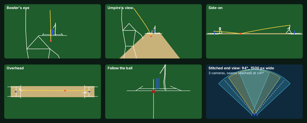
What we designed:
- One scene for every view. The pitch (3.05 m wide), the creases and the six stumps come from the CAD’s Law 6, 7 and 8 sizes (G11-1 to G11-3). The ball is its fitted 3D path at the tracking rate (180 points a second, the B1 plan’s mode). The batter and bowler are 17-point skeletons, the keypoints the pose model gives (COCO order, as MoveNet uses; G11-4, G11-5), 30 a second.
- Five viewpoints from the same data: bowler’s eye (behind the bowler’s stumps, 2.0 m up), the umpire’s view (1.6 m behind, eye at 1.65 m), side-on (26 m out at mid-pitch), overhead (30 m up) and follow the ball (2.5 m behind the ball after the bounce). The phone draws each one; switching view sends nothing new.
- The stitched end view: the three stump cameras at one end (70° lenses, the outer two turned 12°) give 94° and a 1,500 x 800 picture, with 58° of overlap. The seams sit at ±41°.
- A sample ball for the app team:
software/game-view/sample-ball.jsonis the same delivery as the phone decodes it (scene, ball points, skeletons, the call), so the app screen can be built before the stumps exist.
App screen (for the iemi-labs/app repo, built by the app session): a “3D replay” tab on the review screen. Five view buttons, a scrubber over the ball’s 0.57 s flight, the call banner from the stumps (“missing” in the sample), and an “End view” button that asks the brain stump for the three clips. The demo in demo.json keeps its current jobs; this is a viewer of data the review job already has.
How it was checked (29 checks every run):
- every fixed view shows the ball at release, at the bounce and at the striker’s stumps, both striker’s stumps top and bottom, and all 17 points of the batter;
- the follow view keeps the ball within 10 % of the frame centre with the stumps ahead;
- the stitched view spans 94°; the batter (widest point 17.4°), the pitch from 3 m out and the far wicket (widest 26.9°) all stay inside the middle camera, clear of the seams;
- the data checks below.
Data each view needs (measured from a real encoded packet):
| View | Sent to the phone | Size | Time on the stump Wi-Fi (20 Mbps est.) |
|---|---|---|---|
| All five 3D views | one packet per ball: 105 ball points, 90 pose frames for each player (changes only), the call | 7.1 kB (18.8 kB before compression) | 2.9 ms |
| The scene | pitch, creases and stumps, once per match | 0.2 kB | - |
| A whole match in 3D | T20 about 260 balls; 50-over about 640 | 1.89 MB; 4.65 MB | - |
| Stitched end view | three 6 s clips at 4 Mbps (Q6), stitched on the phone | 9 MB | 3.6 s |
So the 3D replay costs about 1,300 times less than the video. It is the default replay for every ball, and every phone at the ground can have it; the end view is fetched only when someone asks.
What we learned:
- The stitch is clean far away and doubles up close. The cameras are 95.3 mm apart, so at the seam a thing 1 m away shows twice, 65.7 px apart; at 5 m 13.1 px; at 20 m 3.3 px; at the boundary 1 px. It is clean (3 px or less) beyond about 22 m. The batter, the pitch and the far wicket never cross a seam, so the play itself is clean; only fielders inside about 22 m and near ±41° show a seam. Next step: move the seam round any close fielder, using the pose model’s position for that player.
- The umpire’s view needs a wide lens. At a normal 30° the umpire’s view loses the bowler’s hand at release (it is 10° above the umpire’s eye); at 52° it shows the whole delivery.
- Pose data is most of the packet. Two skeletons for 3 s are about 18 kB raw; sending only the change between frames brings the whole packet to 7.1 kB. A 29-point skeleton (the broadcast norm, Q6) would add about 70 % to the pose part (est.).
- No new parts. The view runs on the phone from data the stumps already send. Nothing in either order changes.
Changes since the order: none. Order 1 (chip and camera) and order 2 are unchanged.
What is next: run B1 on the real Pi when order 1 arrives (R1), then the app session builds the 3D replay tab from the sample ball; Q12 (B1 update for rev Q) and Q13 (shock proof) follow.
Sources: G11-1 MCC Law 6 The pitch, https://lawsofcricket.lords.org/laws-of-cricket/setting-up-the-game/the-pitch · G11-2 MCC Law 7 The creases, https://lawsofcricket.lords.org/laws-of-cricket/setting-up-the-game/the-creases · G11-3 MCC Law 8 The wickets, https://lawsofcricket.lords.org/laws-of-cricket/setting-up-the-game/the-wickets · G11-4 COCO keypoints (17 points), https://cocodataset.org/#keypoints-2020 · G11-5 MoveNet pose model, https://www.tensorflow.org/hub/tutorials/movenet
R4. STEP and DXF files for makers (31 Oct 2026, rev R row R4; build/cad/maker-files.mjs, build/cad/step/)
The tube shops and print bureaus in build/SHELL.md section 4 quote from CAD files, and some of them only take STEP or DXF, not STL. This run makes those files from the same numbers as the machining drawing and the drilling jig, so the drawing, the jig and the files can never disagree.
What we made (build/cad/step/):
- tube.step: the machined stump wall as a solid: a 38.1 × 31.75 × 651 mm tube with the front notch (4.4 × 3.5 mm), the camera hole (Ø10 at 616 mm), the M3 screw hole (Ø3.4 at 639 mm, back, 90° countersink to Ø6.5), both light slots (6 × 48 mm, z 256-304, front and back) and the lead hole (Ø6 at 300 mm, right).
- tube.dxf: the outside of the wall laid out flat, 119.69 mm (π × 38.1) by 651 mm, with every feature at its true place from the left pencil line (the same datum the jig uses), the end section and the shop notes. The vinyl wrap (row R7) will use the same flat pattern.
- cap-middle.step, cap-side.step, base.step: the printed ends, made from the P1 CAD’s own meshes.
- cap.dxf, base.dxf: the turned outlines through the axis, for a lathe or for the cast-top mould (row R6).
How it was checked (29 checks every run):
- the tube numbers match the machining drawing, the drilling jig and the P1 CAD’s tube;
- the cap’s tab (4 × 3 mm) fits the notch;
- the machined tube is one solid, and a probe finds each of the six features open at its drawing place;
- a Ø31.6 mm plug gauge passes the full length;
- each STEP file is read back from the text alone. Every one is a closed solid with no open edges (tube 3,116 faces, caps 5,258 and 4,738, base 1,868), and its size matches the CAD to 0.01 mm;
- the cap and base outlines match the printed parts’ meshes to 0.06 mm in height and radius.
What we learned: the cap’s highest point is 710.7 mm, not 711.2 mm. The bail groove (11 mm wide) cuts the dome’s crown, as on a wooden stump. The bails sit in that groove, so the wicket’s height under Law 8 is unchanged.
Limits: the STEP files are faceted (flat triangles), which every CAD and CAM program opens. A shop that wants true cylinders can redraw the tube from tube.dxf in minutes, because it is a plain tube with six features. We have not yet opened the files in a second CAD program; the first shop’s quote is that test.
Changes since the order: none. These are files only. Order 1 and order 2 are unchanged.
What is next: R6, the mould plan for the cast white top, starts from cap.dxf. R7, the vinyl wrap, starts from tube.dxf’s flat pattern.
R7. Vinyl wrap for the stump wall (31 Oct 2026, rev R row R7; build/cad/vinyl-wrap.mjs)
The rev R look is a blue stump with two cyan stripes and our name. This row turns it into a print-ready wrap any sign shop can print and cut, made from the same tube numbers as the machining drawing, the drilling jig and tube.dxf.
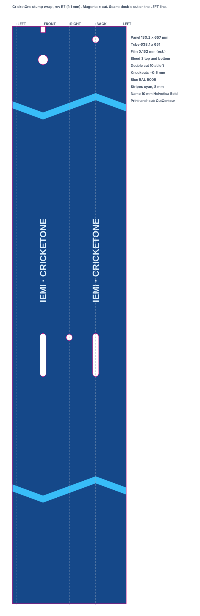
What we designed:
- One panel for all three stumps: 130.2 × 657 mm (0.92 sq ft). That is the tube’s circumference at the film’s mid-line (π × 38.25 = 120.2 mm), plus 10 mm for a double-cut seam on the left pencil line, plus 3 mm to trim at each end.
- Six cut-outs, each 0.5 mm bigger than its hole, so the film edge never sits on a drilled edge: the camera hole, both light slots, the lead hole, the screw countersink and the cap notch. The printer’s plotter cuts them (print-and-cut), so no knife goes near the camera window.
- Two cyan stripes, 8 mm wide, drawn as chevrons: lowest at the front and rising 22 mm round to the back. A straight slanted stripe would not meet itself at the seam; the chevron does, so the seam lands on plain blue.
- The name “IEMI · CRICKETONE” runs up the front and the back between the light slots and the upper stripe (letters 7.2 mm tall).
- Files:
build/cad/wrap/cricketone-wrap.pdf(1:1, CMYK art, cut lines in the CutContour spot colour that print-and-cut software expects) andcricketone-wrap.svg. - Film (est.): 3M IJ180Cv3 cast wrap film (2 mil) under 3M 8518 gloss laminate (2 mil) (R7-1, R7-2). With adhesive, est. 0.15 mm in all.
- How it goes on: drill the tube with the jig first, sand 320, wipe clean. Line the panel’s front line up with the camera hole, wrap both ways, overlap at the left line, cut through both layers on the line and press the butt seam. Trim both ends flush.
How it was checked (24 checks every run): the tube numbers match the drawing, the jig and tube.dxf; the panel is the film circumference plus the seam overlap; every cut-out clears its hole by 0.5 mm and none is near the seam; each stripe meets itself at the seam and misses every cut-out; the name misses the cut-outs and stripes; the PDF reads back with correct offsets, a 1:1 page and seven CutContour paths.
What we learned: a full wrap breaks Law 8.2 on a 1.5 in tube. MCC Law 8.2 allows a stump of 1.38 to 1.5 in (34.9 to 38.1 mm) above the ground (R7-3). Our G-10 tube is already 38.1 mm. The film adds about 0.15 mm a side (est.), so the wrapped P1 stump is 38.40 mm, 0.30 mm over. Paint plus a 2K clear coat adds a similar amount (est.).
- The first stump is a test stump for the lab, so this does not change its build or its tests.
- Production now asks for a tube of 37.6 ± 0.1 mm outside, so the finished stump is 37.80-38.00 mm (the script checks this). The pultruded tube makers in build/SHELL.md section 5 make custom sizes. A stock 1.5 in tube would need its outside sanded down by 0.25 mm, which cuts into the glass fibres (est., not chosen).
- The cap’s shoulder is Ø38.0, so the wrapped wall stands about 0.2 mm proud of it. That is a small step, within the film’s own thickness, not a new edge.
Cost (est.): printed and laminated wrap film runs about $8-15 a sq ft at a sign shop (est.). One stump uses 0.92 sq ft, so about $8-14 a stump, against $3-5 for spray paint and vinyl stripes. The wrap needs no spray booth and no 2K clear coat, and every stump looks the same.
Changes since the order: none. The first stump keeps the paint-and-stripes option in order 2; the wrap is an option.
What is next: wrap the G-10 and pultruded offcuts for the drop and ball tests (row R3) and check that the film stays on after ball strikes and does not lift at the cut-outs. Then the 3D game view (Q11).
Sources: R7-1 3M IJ180Cv3 (2 mil cast film), https://wensco.com/itemdetail/IJ180CV3105450 · R7-2 3M 8518 gloss laminate (2 mil cast), https://www.wensco.com/itemdetail/85185450 · R7-3 MCC Law 8 The wickets, https://lawsofcricket.lords.org/laws-of-cricket/setting-up-the-game/the-wickets
R6. Mould for the cast white top (31 Oct 2026, rev R row R6; build/cad/cap-mould.mjs)
The first stump keeps its printed PA12 caps (FIRST-STUMP.md is unchanged). For the later stumps the white top is cast in our own silicone mould, which brings a cap from a bureau print to about $1.50-2.50 of resin (build/SHELL.md section 5). This row designs that mould and the cast cap, so it can be printed and poured the day the first stump has passed its tests.
What we learned about the materials (Smooth-On’s data pages, sources R6-1 to R6-3):
- Mold Star 30 silicone: Shore 30A, 45 min pot life, 6 h cure, 1.12 g/cc; trial unit 0.91 kg ($37.31).
- Task 16 urethane: Shore 80A/30D, tough and impact resistant, 6 min pot life, 24 h cure, 1.08 g/cc, shrinks 0.25 %. We choose it for the cap: it should take a bail knock and a ball strike without cracking (to be tested).
- Smooth-Cast 65D is harder (65D) but sets in 2.5 min and shrinks 1 %, four times as much; it stays the option if Task 16 caps prove too soft in the bail groove.
- A urethane is a thermoset, so a heat-set insert cannot go in after casting. The M3 brass insert is cast in instead, held on an M3 screw through the mould wall.
What changed on the cap for casting (two things; the outside is identical):
- Hall wire path. The printed cap’s inside cross channel (22 x 3 x 6 mm at 664) cannot be moulded or drilled. Each Hall pocket now gets one straight Ø2.5 hole drilled at a slant from the pocket floor into the wire way: 13.9° for the two pockets of the middle stump’s cap, 6.3° for the outer stumps’ single pocket. A printed hall-drill-guide sits in the bail groove, held in place by end walls on the cap, and guides all three.
- Tab bridge. The tab that drops into the tube’s notch is joined to the spigot. It had a 0.34 mm gap that would have left a thin silicone fin to tear; the bridge sits inside the notch, so the tube still fits.
What we designed (six prints, PETG or PA12):
- cap-master-middle and cap-master-side (38.1 x 38.1 x 74.9 mm): the cast cap before drilling, 0.25 % oversize so the cast shrinks back to size (spigot Ø31.529 printed, Ø31.450 cast).
- mould-box-a and mould-box-b (32 x 84 x 88 mm each): the two halves of the box, bolted with 4 x M4, split across the bail groove (x = 0) so the silicone slides out along the groove.
- mould-lid (64 x 84 x 43 mm): the base under the master while the silicone is poured, then the lid on every cast. It carries the two cores (wire way Ø7.8 x 37.3, key socket 4.3 square for the 4.0 key post), a Ø6 pour hole and four vents: one over the face and three over the air traps (both sides of the shoulder and the tab tip), joined to them by Ø1.5 channels in the silicone.
- hall-drill-guide (44 x 11 x 30 mm): three slanted Ø2.7 guides, 15.5 mm long (6 x the drill).
How to make one: stand the master on the lid’s cores, bolt the box on, put the M3 screw through the back wall to the master, pour 239 g of Mold Star 30 over it and leave it 6 h. Take it apart, cut the silicone along the box seam with a knife and take the master out. To cast: screw a brass M3 insert onto the screw, close the box and lid, pour 78 g of white-tinted Task 16 through the pour hole until it shows in the vents, cure 24 h, unscrew the screw, open the box. Drill the Hall holes through the guide and trim the vent stubs on the shoulder.
How it was checked (45 checks every run): the script draws the P1 cap the same way as the P1 CAD and matches both STL files’ volumes within 0.5 %; the cast cap is one solid, differs from the printed cap by only 0.44 cm³, and fits the machined tube with its notch (no overlap); each Hall drill clears its pocket walls, opens a clear path from the pocket into the wire way and has wall all round; both silicone halves are single solids with at least 8 mm round the cavity; master, lid, box halves and silicone do not overlap in the pour set-up; the lid’s cores sit fully in the master’s holes; every print fits a 256 mm lab printer bed; one Mold Star 30 trial unit (477 g used) makes both moulds.
Cost (est.): the mould prints are about 270 cm³ (est. $8-12 in PETG). Silicone: $37.31 for both moulds. Task 16 per cap: 78 g, est. $1.50-2.50 of resin with the white tint (the trial price is not shown on the maker’s page; est.). Mould life est. 25-50 casts with urethane before the vents and the Hall pocket pins tear; a wicket pair needs 2 middle and 4 outer caps.
What is next: print the masters and box after the first stump’s tests, pour both moulds, cast three caps and check them against the P1 caps: spigot fit with the O-ring, the insert’s pull-out with the cap screw, the bails’ Hall readings through the cast top, and a ball strike on the dome.
Sources: R6-1 https://www.smooth-on.com/products/mold-star-30/ ; R6-2 https://www.smooth-on.com/products/task-16/ ; R6-3 https://www.smooth-on.com/products/smooth-cast-65d/
R5. Drilling jig for the stump wall (31 Oct 2026, rev R row R5; build/cad/drill-jig.mjs)
Every stump wall needs the same six features in the same places, or the camera will not line up with its hole and the lights will not line up with their slots. A printed jig does that without a machine shop, for the first stump and for the cheap pultruded tubes we cut ourselves (build/SHELL.md section 5).
What we designed (three prints, PETG on any printer or PA12):
- jig-top (54 x 54 x 59 mm): a split collar that slides on the top end and stops on the top edge. It guides the camera hole (Ø10 at 616 mm, front), the M3 screw hole (Ø3.4 at 639 mm, back) and the cap notch (4.4 x 3.5 mm in the top edge, front, filed to the jig’s window).
- jig-mid (90 x 60 x 54 mm): a split collar for the lights and the lead. It guides both light slots (6 x 48 mm, front and back, z 256-304: drill Ø6 at each end, then file to the window) and the lead hole (Ø6 at 300 mm, right).
- jig-foot (245 x 54 x 46 mm): a stop plate under the tube’s bottom end with a rail that plugs into jig-mid, so jig-mid sits at the right height. It fits a 256 mm printer bed.
- Each collar is tightened with two zip ties in its grooves. First draw one straight pencil line along the left side of the tube; both collars’ splits sit on that line, so all features lie on one line as the drawing asks. A 1 mm turn error is under 3°, well inside the soft case’s 9 mm light windows.
How it was checked (the script runs 22 checks every time): each print is one solid and fits both a 256 mm lab printer and a 400 x 350 x 350 bureau bed; no jig touches the tube; the top ring sits on the tube’s top edge and the foot plate under its bottom end; the rail reaches the socket floor; a probe through every guide finds it open exactly where the machining drawing puts the feature; each guide is 7.8 mm long, so the drill cannot wander. The positions are the same numbers as the machining drawing (build/figures/rev-r-figures.mjs).
Cost: about 191 cm³ of print (est. $6-10 in PETG on the lab printer, or about $25-40 at an SLS bureau, est.), plus 4 zip ties. Seven tubes do not wear PETG guides; a longer run gets brass inserts in the camera and screw guides.
What is next: print the jig with the first stump’s other prints (order 2) and drill the McMaster G-10 tube with it; check the first tube against the drawing (Ø31.6 plug gauge, features on one line) before the core goes in.
R1. Bench software for the chip and camera (31 Oct 2026, rev R row R1; software/, sim/track2d.mjs)
Order 1 brings only the Pi Zero 2 W and the OV9281 camera, so the first job is the software that answers bench test B1 the day they arrive. The B1 result itself comes from the real Pi; nothing here is a measured result yet.
What we wrote (products/cricketone/software):
setup.sh: camera overlay (dtoverlay=ov9281, auto-detect off), Picamera2 and numpy on Raspberry Pi OS Lite 64-bit.b1_bench.py: asks for 1280 × 800 at 120 fps, 0.1 ms exposure, and reads the sensor’s own time stamp on every frame, so the frame rate and every dropped frame (a gap over 1.5 frame times) come from the camera, not the program. Alongside it the Pi’s H.264 block records a 720p clip from every 4th frame (30 fps): 720p at 120 fps is beyond that block, which is rated about 1080p30 (est.). It logs CPU and SoC temperature each second and writesb1-result.json. Three runs: no clip, with the clip, and with the ball finder on every frame.live.py: a 640 × 400 live view in any browser over the stump’s Wi-Fi, to aim and focus the lens;--trackboxes the ball.track2d.py: the 2D ball finder, with a--selftestthat needs no camera.
The ball finder. A three-frame difference: a pixel counts only when it differs from both earlier frames. At 120 fps the ball moves 5-15 px a frame, more than its 2.9 px size, so it shows only where it is now, with no ghost where it was and no background to learn. The threshold follows the light: 4.5 × the noise, read from the median difference. The finder looks first in a 64 × 64 window where the ball should be, then searches the whole frame in 4 × 4 blocks, and takes only small isolated blobs: 2-20 pixels over the threshold (3 to start a track), with nothing round them, so a moving bowler, batter or bat is never taken for the ball. Our first versions had two faults, and the simulation found both: a learned background left ghost balls (up to 58 wrong fixes in 99 frames), and a 4 × 4 block test with too strict a neighbour rule missed a ball sitting across a block corner.
Simulation check (sim/track2d.mjs, synthetic frames: 1280 × 800 at 120 fps, grass texture, sensor noise, a 2.9 px ball on a 135 km/h delivery 20 m away, a bowler-sized moving block):
| Light | Found | Wrong fixes | Centre error (rms) |
|---|---|---|---|
| Bright day, white ball (contrast 90, noise 3) | 100 % of 99 frames | 0 | 0.048 px |
| Red ball, no filter (contrast 40, noise 3) | 100 % | 0 | 0.106 px |
| Red ball, dull light, high gain (contrast 30, noise 6) | 99 % | 1 | 0.457 px |
The P1 tracking simulation assumed 0.25 px. The finder meets it in good light; in dull light it is 0.457 px, which is what the light rule (P7) already handles by making those calls unsure. Synthetic frames are kinder than a real pitch (no shadows, shimmer or spinning seam), so B1.11 on real turf sets the true figure.
What B1 now decides on the first stump: 119 fps or more with no drops and the clip → keep the Pi Zero 2 W. Drops only with the clip → record clips between deliveries. Under 119 fps with no clip → 1280 × 720 or a 1280 × 400 band, and our RV1126B board (Q10) for production. Finder over 8 ms a frame in Python → move its two inner steps to C.
Nothing on the order changes: FIRST-STUMP.md order 1 and order 2 stay as they are.
Next: R2, print a TPU case sleeve and measure the pull force and rattle in a G-10 offcut.
First build: one stump (31 Oct 2026)
The owner lifted the ordering hold for one stump: the striker’s middle stump (stump-sm), built to rev Q, standing between two plain ICC ash stumps. The parts list, shop by shop, with what one stump can and cannot prove, is build/FIRST-STUMP.md (https://iemilabs.com/build/cricketone-first-stump).
- It can prove:
- bench test B1 (does the Pi Zero 2 W reach 120 fps with the OV9281 while encoding 720p);
- bail-off on both grooves;
- the call lights and tone through the G-10 slots;
- power and a 2-hour soak;
- tamper and signing;
- knock and drop;
- weight and balance against a real ash stump;
- live video to a phone;
- 2D ball tracking.
- It cannot prove: 3D ball tracking, LBW, height and bounce. These need the far-end cameras, so they wait for the other five stumps.
- Bought camera: it has a 79° lens, not the design’s 70°, so about 2.9 pixels on the ball at 20 m instead of 3.3 (est.); B1 measures it.
- Cost: about $1,390-1,480 with tools, $1,050-1,140 without (est.; carts filled 31 Oct 2026, the owner pays).
- Lab runs: every 30-minute run now refines CricketOne only, and writes any part change into FIRST-STUMP.md “Changes since the order”.
Rev Q (31 Oct 2026): owner review, the design made real
The owner reviewed P1 before paying and found real flaws. All ordering is on hold until they are fixed. Each finding, what we checked and what changed:
Q1. Can the camera see the ball out to the boundary? (sim/camera-pixels.mjs)
A 72 mm ball needs about 3 pixels across to be tracked, and about 2 to be seen at all.
| Camera (70° view unless noted) | Ball at 20 m | at 40 m | at 80 m | Tracks to | Shutter |
|---|---|---|---|---|---|
| OV9281 1 MP mono (P1) | 3.3 px | 1.6 px | 0.8 px | 22 m | global, 4 mm smear |
| AR0234 2.3 MP colour | 4.9 | 2.5 | 1.2 | 33 m | global |
| IMX708 12 MP colour (Camera Module 3, 66°) | 12.8 | 6.4 | 3.2 | 85 m | rolling, about 14 fps at 12 MP |
| IMX708 Wide (102°) | 6.7 | 3.4 | 1.7 | 45 m | rolling |
What we learned.
- No stump camera can track a 90 mph ball at 80 m. That would need about 4,700 pixels across a 70° view at 120+ fps with a global shutter. No small sensor does it, and none would fit a 38 mm stump.
- The bigger limit is direction. A stump camera looks along the pitch, so even a wide lens sees only 39-57 % of the boundary, and never square of the wicket.
- Every call the stumps make is at the wickets, within 22 m, where the 1 MP global-shutter camera tracks at 3-13 px with 4 mm of smear. So the tracking camera stays.
- Decision: the stumps make no boundary calls (four, six, catches near the rope). Those stay with the umpires and scorers, who can tap them in the app. The middle stumps get a colour scene camera (IMX708 Wide class) for viewers and the 3D game view (Q6). It sees a ball near the rope at about 2 px, which is good for watching but not for deciding.
Q2. How does a small board process high-quality video?
No board processes all six cameras. Each stump handles only its own camera:
- it finds the ball in a small window round where the ball should be, not in the whole frame;
- it runs the pose model a few times a second;
- it encodes its own video with the chip’s hardware encoder (H.264 at 720p30, about 3-5 Mbps).
The brain stump receives only points, times and calls (a few kB/s). Viewers’ video goes from one stump to the phones on request (Q6).
The pixel load for the tracking camera at 1280 × 720 × 180 fps is 166 Mpx/s. That rate is bench test B1’s main question on the Pi Zero 2 W: one Pi 4 user measured only about 30 fps with libcamera, while Arducam’s table claims 143 fps in RAW8.
Q3. Is clear polycarbonate right for a hard ball? (sim/shell.mjs)
No.
- A 38.1 mm polycarbonate tube with a 3.2 mm wall has 0.10× the bending stiffness of an ash stump, so it would whip and ring on every hit.
- Polycarbonate also crazes from isopropyl alcohol (critical strain 1.21 %) and from cyanoacrylate fumes, and it yellows in UV.
- MCC Law 8.1 requires wooden stumps and bails. No plastic or glass-fibre stump is legal for sanctioned matches, whatever its size.
| Wall | Stiffness vs ash | Wall mass | Law 8.1 | Use |
|---|---|---|---|---|
| Polycarbonate, 31.75 bore | 0.10 | 297 g | no | dropped |
| G-10/FR4 glass-epoxy, 31.75 bore (McMaster 6394A37) | 0.73 | 458 g | no | P1 lab build: same bore, so every print fits unchanged; radio-transparent |
| Ash, bored 28 mm | 0.71 | 252 g | yes | production: a real ash stump, bored; needs our 22 mm-wide board |
| Ash, bored 31.75 | 0.52 | 167 g | yes | rejected: a 3.2 mm wood wall is too thin to take a ball |
| 6061 aluminium | 2.97 | 669 g | no | rejected: blocks the radio, dents |
Decision.
- P1 lab build: a G-10 tube with three openings, all lined up with the camera by a tab on the cap that drops into a notch in the tube’s top edge:
- a Ø10 camera hole at 616 mm;
- two 6 × 48 mm light slots at 256-304 mm, filled with clear strips.
- Production: a turned English ash stump bored to 28 mm (a 5 mm wall), the same wood as match stumps. It is Law 8.1 legal and lighter than solid ash.
- It takes A123 26650 cells (Ø26) and our own board, at most 22 mm wide.
- The camera looks out through a toughened glass window set in the wood.
- The lights shine through small clear inserts.
Shock. A ball knocks a stump at about 10 m/s (9.4 N·s on about 0.9 kg).
- Soft mounts cannot soften a 10 m/s change in a 2-3 mm bore: stopping 10 m/s in 2 mm is 2,500 g, worse than rigid.
- So the parts are held solid and fully supported: boards bonded flat to the carriers, cells packed in their sleeve, no part hanging on its solder joints.
- A soft silicone layer (not hard epoxy) damps the wall’s ringing.
- Ratings, against about 1,000 g for 1 ms at the stump:
- cells: UN38.3 is 150 g for 6 ms, a similar 9 m/s change;
- industrial microSD: 1,500 g;
- camera connectors: 50 g for 11 ms.
- The ball-cannon test T1 is the proof. The camera connector is the weak point, so production solders the camera to the board.
Q4. A real stump: nothing underground, real size
- Owner rule: only the spike goes in the ground.
- Rev Q moves all three cells above the grass (z 34-234), in one stainless sleeve.
- The shell starts at the grass, and a solid 102 mm spike (no electronics) goes into the ground.
- Overall length: 711.2 above the ground (Law 8.2) + 102 = 813 mm. Retailers give match stumps as about 31-32 in (787-813 mm) overall.
- Diameter 38.0-38.1 mm, inside Law 8.2’s 35.0-38.1 mm.
- The P1 tube is cut 651 mm, from the grass to under the cap.
- The CAD checks both.
- The cost: the stump is heavier at the top. The mass table now puts the balance point at 279 mm (ash: 327 mm), at 938 g against about 470-580 g for ash. The ash shell (Q3) brings it down by about 200 g. (Row Q14, 1 Nov 2026: the rev R first stump is 1,012 g with its balance point at 295 mm; see “### Q14”.)
Q5. The umpire band is removed
- The band (pod, lid, keys, XIAO, e-paper, LiPo, motor) is in no use case.
- Calls now show on the stumps (lights and tones) and in the phone app. The umpire, scorer or captains get a buzz on their own smartwatch through the phone, and answer unsure calls in the app.
- The product is the six stumps and four bails, with no other part.
- The band’s CAD, BOM rows, wiring figure and test sketch are removed.
Q6. Video to the phone, and a 3D game view
How video moves:
- Recording. Every stump keeps the last 20 s of its own camera in memory and encodes 720p30 H.264 in hardware (3-5 Mbps).
- Live view. The phone picks one stump at a time over the stumps’ own Wi-Fi: one stream, not six.
- Replays. After each ball the brain stump has every point, time and call. Clips (6-10 s from each camera, about 3-6 MB each) come to the phone only when someone asks.
The 3D game view is rebuilt, not stitched: broadcast ball-tracking graphics work the same way.
- Ball: its real 3D path from the flight fit, to the mm.
- Players: batter and bowler as 3D figures, driven by the pose model’s keypoints from several stumps (29-point skeletons are the broadcast norm).
- Scene: the pitch, wickets and creases from the CAD.
- Viewpoints: the viewer chooses: bowler’s eye, umpire’s view, side-on, overhead, or follow the ball.
Stitched end view. The three cameras at each end overlap (each 70°, the outer two turned 12°), so their pictures stitch into one wide picture of about 94°. Because the cameras’ positions are known from self-calibration, the stitch is computed once and reused, so it is cheap. The middle stumps’ colour scene camera textures the 3D pitch.
What we will not claim. True free-viewpoint video, as Intel True View does with 38 cameras, cannot be built from six cameras near the ground at two ends. Research methods need wider, surrounding views. A cloud “highlight” version is a later option.
Q7. Which board, and why
| Board | For | Against | Verdict |
|---|---|---|---|
| Raspberry Pi Zero 2 W | OV9281, IMX708 and IMX296 work out of the box; hardware H.264 1080p30; fits 65 × 30; $15-19 list | no NPU (pose about 3/s est.); 512 MB; one camera port; out of stock at list price | P1 bench and lab build (owner decision, 30 Oct) |
| Radxa ZERO 3W (RK3566) | 0.8 TOPS NPU; H.264/H.265 encode | Radxa officially supports only OV5647 and IMX219 cameras, so OV9281 needs our own driver work; one camera port | comparison only in B1 |
| Raspberry Pi CM5 | fast; 2 camera ports | 55 × 40 mm, does not fit; no hardware video encoder | rejected |
| Rockchip RV1126B (camera SoC) | 3 TOPS NPU; two 4-lane camera ports; AI-ISP; H.264/H.265 encode up to 12 MP at 30 fps; made for smart cameras | no board narrow enough exists (the smallest module is 38 × 30), so we design our own 22 mm-wide board | production |
Why. P1 needs a board that works with our camera today, so it is the Pi Zero 2 W. Production needs two cameras (tracking and colour scene), a neural engine and a hardware encoder in a 22 mm-wide board that fits a bored ash stump. The RV1126B is the camera-class chip with all three.
Q8. What changes, and what is next
- CAD:
- rev P product CAD: shell from the grass, cells above it, solid 102 mm spike, no band;
- P1 CAD: tube from the grass (651 mm), G-10 tube, cap tab, carriers moved up.
- Simulations:
sim/camera-pixels.mjs(Q1) andsim/shell.mjs(Q3) are new. - Order, when the hold lifts:
- G-10 tubes instead of polycarbonate;
- band parts off;
- no IPA or CA on the tube;
- the 3D game view and live view go into the app plan.
- Next rows:
- Q9: the production ash stump: bore, window and wood checks, with a turning shop quote;
- Q10: the RV1126B 22 mm board outline;
- Q11: an app prototype of the 3D game view from the simulated tracks;
- Q12: B1, now including whether the Pi Zero reaches 120 fps with the OV9281.
Production ash stump (31 Oct 2026, row Q9; sim/ash-stump.mjs, CAD section “row Q9”)
MCC Law 8.1 says stumps are wooden, so production CricketOne is a real English ash stump with a 28 mm bore. The P1 G-10 tube stays the lab build for the first stump’s tests. All figures are calculated from the sources below; wood varies, so they are est. until the B1 wall coupons and the T1 ball cannon.
Wood (European ash, 12 % moisture). 710 kg/m³, bending strength 103.6 MPa, stiffness 12.3 GPa along the grain (W1). Across the grain ash is far weaker: compression 8.0 MPa, tension 6.5 MPa, stiffness about 7 % of the along-grain value (W2).
1. How to bore it.
| Method | Depth / bore | Wall | Verdict |
|---|---|---|---|
| Gun-drill from the top | 25 | the drill follows the grain: 1-2 mm drift over 700 mm (est.), wall 3-7 mm | only if the outside is turned on a bore mandrel afterwards |
| Drill from both ends, turn on a mandrel | 12.5 | a 0.3-1 mm step where the holes meet (est.) | rejected: it opens the bottom, and the spike must stay solid |
| Two bookmatched halves, half-channel cut, glued, turned on the bore | - | 5.05 ± 0.2 mm all round (est.) | chosen |
- Chosen method. Split one quarter-sawn ash billet, cut a Ø28 half-channel in each half, glue the halves, then turn the outside true to the bore.
- The bore is straight and blind: it runs from z 10 up to the crown, so the 102 mm spike stays solid ash and is the stump’s own pointed end.
- The window cup and light insert holes are cut before gluing.
- The glue line sits in the side plane, out of the line of front and back hits.
- Crown plug. A bonded ash crown plug (z 668-711) closes the top on an O-ring and carries the bail groove and the Hall sensors. The electronics stack slides in from the top, so the stump can be serviced.
2. Can a 5 mm ash wall take a 40 m/s ball? P4’s loads at 145 km/h are 9 kN mean and 14.8 kN peak, over a patch of about 30 × 18 mm.
| Case | 9 kN | 14.8 kN | Limit | Result |
|---|---|---|---|---|
| Whole stump bending | 0.71 × solid ash (398 N·m) | flies out of the ground, as solid ash does (P4) | same behaviour as a match stump | |
| Hollow wall (air or foam behind it), ring bending across the grain | 209 MPa | 344 MPa | 6.5 MPa across the grain | splits along the grain |
| Wall backed solid: face at the ball | 16.7 MPa | 27.4 MPa | 8.0 MPa | dents, exactly as a solid ash stump does |
| Wall backed solid: onto the core | 8.0 MPa | 13.1 MPa | PA12-GF about 70, filled epoxy about 100, PU foam about 1 | carrier or filled epoxy, never foam |
- What we learned. A bored wooden stump carries a ball in its weak direction, across the grain. A hollow wall would split on the first hard hit.
- The rule. The bore is full at every height: cells in their stainless sleeve, boards in a round PA12-GF carrier, and filled epoxy behind the window. Each is bonded to the wood with a 0.3 mm silicone layer.
- The silicone layer. It is thin and boxed in, so it acts almost solid in compression (about 1.4 GPa, est.). It squeezes only about 3 µm at the peak load, yet it still damps the wall’s ringing (Q3).
- This changes P6. P6’s foam-filled electronics bay is not used in the ash stump.
3. Camera window. The ball’s patch covers the whole Ø12 glass, about 2.2 kN at peak.
- An ash ledge crushes. Cut in the wood, the ledge carries 54 MPa across the grain, against a limit of 8.0.
- So the glass sits in a 316 stainless cup. The cup is Ø16, with a Ø9 aperture, bonded in the wall and backed by the epoxy ring behind it, so the core sees about 15 MPa.
- Below the surface. The glass sits 0.3 mm below the wood, so the cup and glass add no new hard edge.
4. Call light. Twelve clear Ø4 polycarbonate inserts, six on each side wall at z 262-302, take the place of the G-10 slots.
- Where they sit. The side walls are the neutral axis for front and back hits, so the inserts stay out of the most stressed wood. In the CAD they sit above the top cell and below the secure element.
- Bonding. Silicone only: polycarbonate crazes from CA glue and alcohol (Q3).
- Light area. The inserts have about 26 % of the slots’ light area. The first stump’s light test sets how bright the LEDs must be (est.).
5. Radio out through the wood (2.45 GHz, 5.05 mm wall; wood dielectric ranges from W3, est.):
| Wood | Loss in the wall | Reflection, both faces | Total |
|---|---|---|---|
| Dry, 8-12 % moisture | 0.18 dB | 0.45 dB | 0.63 dB |
| Damp after dew, about 18 % | 0.34 dB | 1.02 dB | 1.36 dB |
| Soaked surface, about 30 % | 0.62 dB | 1.84 dB | 2.45 dB |
Even a soaked stump costs 2.45 dB, against P8’s smallest link margin of 15.9 dB. So the radio works through the wood and needs no slot. The bore is sealed with oil so the wood’s moisture moves slowly.
6. In the CAD (node cad/cricketone-cad.mjs, writes sim/ash-stump-cad.json). The CAD draws the stump at its legal size:
- Ø38.1 and 711.2 mm above the ground, 813.2 mm overall;
- the blind bore from z 10 to 668;
- the cup seat;
- the 12 insert holes;
- the crown plug.
It checks:
- the wall is 5.05 mm all round;
- an A123 26650 cell fits in its sleeve and silicone layer (Ø28);
- a 22 mm board’s corners fit inside the Ø27 carrier;
- the window cup fits in the wall;
- the inserts clear the cells and the secure element.
Mass: the bored shell and crown plug weigh 324 g, against 613 g for a solid ash stump of the same shape. That is 134 g lighter than the G-10 wall, which helps Q14.
7. How to get a price (research only, no orders). Send the same request to three kinds of shop: a cricket stump or bat maker that already turns ash stumps, a CNC wood-turning shop, and a gun-drilling shop as the comparison. The request includes:
- the CAD drawing;
- Law 8 sizes;
- quarter-sawn English ash at 10-12 % moisture, with straight grain (slope no worse than 1 in 15);
- the bore method and a wall of 5.05 ± 0.2 mm;
- the window cup seat and the 12 insert holes;
- the crown plug;
- quantities 6, 60 and 600.
Ask for the price per stump, the tooling cost and the lead time. Price per stump at 60: about $25-60 (est., no quote yet). The spare ash stump in the first-stump order is for practising the half-channel cut.
Open questions for the owner:
- Should the governing bodies be asked early whether small clear light inserts and a glass window keep a stump “wooden” under Law 8.1? Until they agree, the stumps only assist in sanctioned matches.
- Should the bore surface get an oil seal, or a thin epoxy seal (better against moisture, harder to repair)?
- Should the glue line run in the side plane (chosen), or should a single-piece gun-drilled stump be tried as well?
Sources: W1 https://www.wood-database.com/european-ash/ · W2 USDA Forest Products Laboratory, Wood Handbook FPL-GTR-282, Tables 5-1 and 5-3b, https://www.fpl.fs.usda.gov/documnts/fplgtr/fpl_gtr282/fpl_gtr282.pdf · W3 Torgovnikov, Dielectric Properties of Wood and Wood-Based Materials (Springer 1993), https://link.springer.com/book/10.1007/978-3-642-77453-9 · MCC Law 8, https://lawsofcricket.lords.org/laws-of-cricket/setting-up-the-game/the-wickets · ball loads P4 (sim/impact-results.json), link margin P8 (sim/rf-results.json).
Our 22 mm stump board (31 Oct 2026, row Q10; sim/stump-board.mjs)
The production stump is bored English ash (Q9): a Ø28 bore, a round Ø27 carrier inside it, and a board no wider than 22 mm. The smallest RV1126B module we found is 34 x 30 mm (S4), and the Radxa ZERO 3W that P12 costed is 30 mm wide, so neither fits the ash bore. This row outlines our own board. It is research only: no quote was asked for and nothing was bought. node products/cricketone/sim/stump-board.mjs writes sim/stump-board-results.json.
The chip: RV1126B-P. Rockchip sells the RV1126B in two packages, both 14 x 14 mm (S1):
- RV1126B: FCCSP-491 with mixed 0.42 / 0.5 / 0.65 mm ball pitch, which needs a finer, dearer board;
- RV1126B-P: FCCSP-409, all 0.65 mm pitch (chosen). It keeps both 4-lane camera ports and the 32-bit memory bus (S2).
What is on the board (sizes from the datasheets; prices est. where no public price exists):
| Part | Size (mm) | Side | Job | Source |
|---|---|---|---|---|
| RV1126B-P: 4 x Cortex-A53, 3 TOPS NPU, ISP up to 12 MP at 30 fps, H.264/H.265 encode up to 12 MP at 30 fps | 14 x 14 x 1.1 | top | all of the stump’s work | S1, S2 |
| LPDDR4X 8 Gbit x32 (1 GB) | 10 x 14.5 x 1.0 | top | memory | S3 |
| RK809-class PMIC and its inductors | 7 x 7 chip, 10 x 14 zone | top | the chip’s power rails | S5 |
| AMPAK AP6256 Wi-Fi 5 + Bluetooth 5, pre-certified | 12 x 12 x 1.65 | top | the stumps’ own Wi-Fi and the phone link | S6 |
| chip antenna with a 6 mm keep-out at the board end | 6 x 20 | top | radio out through the wood (Q9: 2.45 dB worst) | est. |
| two camera flex lands | 6 x 18 | top | tracking OV9281; colour scene IMX708 class on the middle stumps | Q3, Q7 |
| eMMC 5.1 8 GB, industrial, 153-ball | 11.5 x 13 x 1.0 | bottom | software and the 20 s clip buffer overflow | S7 |
| buck-boost 2.5-3.6 V to 3.6 V, LiFePO4 charger | 8 x 10, 6 x 8 | bottom | power from the three A123 cells and the charge pads | est. |
| LSM6DSOX motion sensor, ATECC608B secure element | 2.5 x 3, 2 x 3 | bottom | stump knocked; signed calls (now chips on the board, not breakouts) | bom.csv |
| 12-channel constant-current light driver | 3 x 3 | bottom | the call lights behind the 12 clear inserts | est. |
| bail inputs: filters into the chip’s own 13-bit SARADC (3 x 8 channels, 2 MS/s) | 4 x 6 | bottom | bail-off timing (P18); no extra ADC needed | S1 |
| crystals and passives | 6 x 18 | bottom | clocks | est. |
1. Does it fit 22 mm? Yes.
- The widest part is the 14.5 mm memory, against 20 mm inside the 1 mm board edges.
- Packed end to end, the top side runs 67.5 mm and the bottom 58.5 mm, so the board is 22 x 68 x 1.0 mm (8 layers, one step of laser vias, est.).
- In the Ø27 carrier there is 7.3 mm of room above the board right at its edge. The tallest part (the 1.65 mm Wi-Fi module) clears the carrier by 7.1 mm, and the closest (the antenna end) by 3.4 mm.
- Above the chip there is about 9.9 mm to the carrier wall, room for the copper spreader P3’s heat model asks for.
- Where it sits: z 579-647, its top end 8 mm under the camera axis (z 655), so the camera flex folds straight up to the window. It is well above the light inserts (z 262-302) and below the crown plug (z 668).
2. Can it take both cameras?
| Camera | Pixels a second | Data | Share of a 2-lane link | Share of the ISP |
|---|---|---|---|---|
| Tracking OV9281, 1280 x 720 at 180 fps, RAW10 | 166 Mpx/s | 1.66 Gbps | 0.33 | together 0.71 of 12 MP at 30 fps |
| Colour scene IMX708 class, 2304 x 1296 at 30 fps (middle stumps) | 90 Mpx/s | 0.90 Gbps | 0.18 |
Each camera needs only two of its port’s four lanes, and together they use 71 % of what the ISP takes in. The 166 Mpx/s that bench test B1 must prove on the Pi Zero 2 W (Q2) is well inside this chip’s rating. The NPU (3 TOPS against the ZERO 3W’s 0.8) runs the pose model at full rate, not 3 a second.
3. Power (est., until the first board is measured).
- In a delivery: about 3.5 W (chip with NPU, ISP and encoder busy 1.8, memory 0.35, Wi-Fi sending 0.6, cameras 0.45, lights and the rest 0.3).
- Between balls: about 1.3 W.
- Average, with a ball live about 3 s in every 20 s: about 1.63 W, against rev P’s 1.5 W.
- The three A123 cells give about 12.3 h at that rate (10 % reserve, 90 % conversion). A 50-over day is about 8-9 h, so the margin is smaller than P15’s but still there; P15’s runs are re-done when the board is measured.
4. Cost per stump (est.). Parts, an 8-layer HDI board and two-sided assembly with X-ray:
| Build | 1 kit | 100 kits | 1,000 kits |
|---|---|---|---|
| Our RV1126B-P board (Q10) | $124 | $69 | $55 |
| P12 option B: ZERO 3W + our carrier (does not fit the ash bore) | $78 | $56 | $50 |
| P12 option C: our RK3566 board (one camera port, 0.8 TOPS) | $133 | $69 | $57 |
What we learned.
- The ash stump decides the board. Option B, the cheapest in P12, cannot go into a 28 mm bore because the ZERO 3W is 30 mm wide. So production needs a custom board whichever chip it uses.
- For about the same money as P12’s option C, the RV1126B-P gives two camera ports, 3.75 times the NPU and a camera-grade ISP. At 100 kits it costs about $13 a stump more than option B, about $78 a kit.
- The radio keeps a module grant. The AP6256 is pre-certified (FCC ID ZQ6-AP6256, P12 G9), so the product needs a host filing and the RED test set from P8, not a new radio approval.
- The risk is bring-up, not fit: the 32-bit LPDDR4X layout and its training, and the two camera drivers. The OV9281 driver work found in P2 is the same on this chip family.
Design houses and costs (research only, est.; nobody was asked).
| Kind of design house | One-off cost | Weeks | Note |
|---|---|---|---|
| An RV1126B module maker with a custom carrier or custom module service (S4) | $15,000-30,000 | 10-14 | has the reference layout, memory settings and Linux support; ask whether the layout files become ours |
| An independent embedded hardware design house with Rockchip experience | $25,000-50,000 | 12-20 | we own everything; memory bring-up is the risk |
| A freelance HDI layout engineer, from Rockchip’s reference schematics | $10,000-20,000 | 14-24 | cheapest; we carry the bring-up and the software |
Add two prototype rounds of about 10 boards each: about $3,000-6,000 (est.). Send every kind the same request: this outline, the parts table, the Ø27 carrier drawing, the camera modes above, quantities 6, 60 and 600, and a request for the price, the lead time and who owns the files.
The first stump is unchanged. P1 keeps the Pi Zero 2 W and the G-10 tube; nothing on the first-stump parts list changes. The board is designed only after the first stump passes B1 and T1.
Open questions for the owner:
- Which kind of design house should be asked first, and should owning the layout files be a must?
- 1 GB or 2 GB of memory? 1 GB is chosen (the 20 s clip buffer is about 12 MB); 2 GB adds about $4 a stump (est.).
- Should the colour scene camera go on all six stumps, so every board is the same, or only on the two middle stumps (chosen; the board has the second port either way)?
Sources:
- S1 Rockchip RV1126B Datasheet Rev 1.1 (package FCCSP-491 / FCCSP-409, 14 x 14 mm; 2 x 4-lane MIPI D-PHY 2.5 Gbps a lane; ISP 12M at 30 fps; encoder 12M at 30 fps; NPU 3 TOPS INT8; SARADC 3 x 8 channels, 13-bit, 2 MS/s): https://macrogroup.ru/upload/iblock/d7a/yay5h3kvj0rcd7y199bm2ie1a7gabcbm/RV1126B.pdf
- S2 CNX Software, RV1126B-P in a vision module (FCCSP-409, 0.65 mm pitch; 32-bit LPDDR4/4X; module 38 x 30): https://www.cnx-software.com/2025/09/02/rockchip-rv1126b-p-quad-core-cortex-a53-soc-shows-up-in-ai-vision-system-on-module/
- S3 DigiKey, Alliance Memory LPDDR4 200-FBGA (10 x 14.5): https://www.digikey.com/en/products/detail/alliance-memory-inc/AS4C128M16MD4-062BAN/13563586
- S4 CNX Software, Boardcon Tiny1126B, the smallest RV1126B module found, 34 x 30 mm, RK809 PMIC: https://www.cnx-software.com/2026/04/17/boardcon-tiny1126b-smaller-lighter-rockchip-rv1126b-system-on-module-yet-with-more-ios/
- S5 LCSC, Rockchip RK809-5 (QFN-68, 7 x 7): https://www.lcsc.com/product-detail/C2939628.html
- S6 LCSC, AMPAK AP6256 (12 x 12; SDIO Wi-Fi, UART Bluetooth): https://www.lcsc.com/product-detail/C5248079.html
- S7 ISSI IS21/22TF08G eMMC 5.1 datasheet (153 FBGA 11.5 x 13 x 1.0 mm, -40 to 85 °C): https://www.mouser.com/datasheet/2/198/ISSI_6_8_22_IS21_22TF08G__Rev_A_0426_2022-3132334.pdf
- P12 option prices: sim/board-cost-results.json; carrier and bore: sim/ash-stump-cad.json (Q9).
CAD review: 31 Oct 2026 (row Q10), no assembly change; the board outline is checked against the Q9 ash bore in sim/stump-board.mjs (fits 22 mm, clears the Ø27 carrier, z 579-647 between the light inserts and the crown plug); package sizes from datasheets S1-S7; no floating parts.
Phase 2 engineering, rev P (30 Oct 2026): accurate, safe and to standards
The owner chose CricketOne as IEMI’s first product and started phase 2 a day ahead of plan. Phase 2 makes the design accurate, safe and to standards before anything is built. The first review asked four questions. The answers, numbers, design changes and tests are below, and the product page shows the same content from engineering.json (“Engineering” section). Numbers marked est. are calculations, not test results.
What changed in rev P (CAD, bom.csv, integration.json, equipment.json):
-
The same build in all six stumps. Each stump has:
- a 1 MP global-shutter camera (OV9281 class, Arducam mini 24 x 25) behind a Ø12 window on a ledge;
- a Radxa ZERO 3W (RK3566, 0.8 TOPS NPU, 65 x 30; the Pi Zero 2 W is the same size and the fallback) behind a 6061 aluminium D-bar;
- our power board (TI BQ25070 LiFePO4 charger, TI TPS61023 boost, ST LSM6DSOX motion sensor, cell monitor) and an ATECC608;
- three A123 ANR26650M1-B LiFePO4 cells, the lowest at z -68.5 to -3.5 (below the grass);
- two flush 316 stainless charge pads;
- the rev O call light, sounder, tamper switch and Hall sensors.
Any stump can stand anywhere; the brain is a software role.
-
Removed: the Raspberry Pi AI Camera (IMX500), Pi Zero 2 W, PowerBoost 1000C, Samsung 18650 cells, XIAO nRF52840 Sense and XIAO ESP32-S3 Sense.
-
Stump body:
- the light slots have round R3 ends;
- the camera window is a Ø12 pocket with a Ø9 aperture, so the ledge takes a hit;
- two Ø6 charge-pad holes at the back;
- the spike plug is 24 mm (was 30), so the lowest cell fits below the grass.
Law 8 is still asserted: Ø38.0, top 710.7, wicket 228.6, bails rise 7.5. All fit checks pass, the assembly has no collisions, and the camera views pass
inView()for 13 targets, including the release point, the bounce at 2 m and 7 m, and pad impact. -
Cost and price:
- Parts are about $1,280 at qty 1 (about $1,469 after row P4’s glass-fibre tube and toughened windows; bom.csv; camera $25.99, Radxa ZERO 3W $29.99 and A123 cell $9.94 checked 30 Oct 2026, the rest est.). That is up from $992, because there are six cameras and computers instead of two cameras.
- Target price is $1,690 → $1,990 (extra pair $1,290 → $1,490). Confirmed by the owner on 30 Oct 2026; the phase 3 buyer review checks it with clubs.
- At volume, one long, thin carrier board of ours below the Radxa ZERO 3W and a bare camera module replace the dev boards (row P12: about $105 a kit at 100 kits, est.); the custom call-light strip saves about as much.
P1. Tracking a 90 mph ball
The question: at 80-90 mph the ball covers the 22 yards in under half a second. Frames come metres apart, so how is it tracked, and at what resolution?
The honest answer for rev O: it could not. The IMX500 AI camera runs at about 30 fps with a rolling shutter. A 40.2 m/s ball moves 1.34 m between frames, and is skewed by the rolling readout. That is fine for slow things (a planted front foot, the count, fielders) but not for a ball track. Rev O already rated LBW “not rated”, and rev P is what makes a rating possible.
| Quantity | Value | How |
|---|---|---|
| Ball speed | 90 mph = 40.2 m/s | |
| Release to the batter | about 0.44 s over 17.8 m | 17.8 / 40.2 |
| Distance per frame | 1.34 m at 30 fps, 0.34 m at 120 fps, 0.20 m at 200 fps | v / fps |
| Six stumps, shutters staggered at 200 fps | about 1,200 looks a second, one every 34 mm | 6 x 200, est. |
| Motion during a 0.1 ms exposure | 4 mm | global shutter, short exposure in daylight |
| Pixel scale (70° over 1280 px) | 4.8 mm/px at 5 m (ball 15 px), 19 mm/px at 20 m (ball 4 px) | |
| Length from the bounce (ground plane, camera at 655 mm) | about 2 mm at 2 m, 6 mm at 4 m, 13 mm at 6 m, 23 mm at 8 m for a quarter-pixel centroid | est. |
| Stereo depth across the three stumps (190.6 mm baseline) | about 6 mm at 2 m, 36 mm at 5 m, 0.14 m at 10 m | est. |
Why resolution is not the main lever. More pixels means fewer frames a second over the same link. A 1 MP global shutter at 120-200+ fps beats a 12 MP rolling shutter at 30 fps for a ball. The OV9281 is 1280 x 800 at 120 fps on 2 MIPI lanes (OmniVision product brief); the cropped band we read in a delivery (about 1280 x 400) must be measured on the real board (bench test B1).
How the track is built:
- Staggered shutters. Six cameras’ shutters are staggered, with clocks synced to about 0.05 ms (est.). The ball moves 2 mm in that time.
- Each stump finds the ball itself. It uses frame differencing in the cropped band, with the NPU confirming the object is a ball. It sends only (u, v, t) points, never video.
- One physical flight is fitted through all points. The model has gravity, quadratic drag, swing (a lateral term), the bounce (restitution and skid), and the impact. No single pixel decides a call, and the fit residual is the confidence.
- Where each axis comes from. The stump cameras look along the pitch. Line and height come straight from the image. Length comes from the bounce: at the bounce the ball’s height is zero, which fixes its distance by ground-plane geometry. The flight time and the three-stump stereo near each end also help.
- The main LBW view is from the bowler’s-end stumps. They see the ball from behind, so the batter cannot block them. The striker’s-end stumps add the bounce and the impact when the batter’s legs leave them a view.
- Self-calibration every match. Each camera finds the far stumps, whose size Law 8 fixes (228.6 x 711.2 mm), and the creases. The motion sensor measures each stump’s lean.
- Run-outs and stumpings take the bail-off time to the millisecond from the Hall sensors. The bat’s position is interpolated between frames: at 200 fps a bat at 6 m/s moves 30 mm per frame.
Targets (est., to be proven):
- line at the stumps within ±25 mm for impacts within 2.5 m;
- run-out bat gap within ±20 mm;
- the wide line within ±30 mm.
LBW stays evidence only until field tests rate it.
Tests:
- B1: the cropped frame rate on the Radxa ZERO 3W and on the Pi Zero 2 W.
- B2: 200 ball-machine deliveries at 145 km/h, tracked against a 1,000 fps reference camera.
- B3: 100 staged run-outs filmed side-on at 1,000 fps.
Limits:
- Floodlights and dusk need longer exposures, so LBW evidence is marked unsure.
- A low sun straight down the pitch blinds one end; the other end carries the track.
P1 simulation: ball tracking (30 Oct 2026, row P1)
node products/cricketone/sim/track-sim.mjs (seeded, no dependencies, about 7 minutes; full results in sim/track-sim-results.json). Every number below is simulated, not measured.
What it simulates.
- Deliveries: 200 at 120-150 km/h. Release 1.9-2.3 m high, up to 0.6 m either side of the stumps. Swing of ±3 m/s² that also changes during the flight (±4 m/s³), drag varied ±15 %. Bounce 2-8 m in front of the striker’s stumps, with restitution 0.45-0.60, skid 0.85-0.95 and a seam kick of 0.35 m/s.
- The pad: it stops the ball 0.4-2.5 m in front of the stumps.
- The batter: a body 0.4 m wide and 1.75 m tall in front of the stumps, which hides the ball from the striker’s-end cameras.
- Cameras: six, at the CAD positions (x = -95.3 / 0 / +95.3 mm, 655 mm up, 12° down, windows 19 mm in front of the stump centres, 20.12 m apart). Each is 70° wide (f = 914 px) and reads a 1280 x 400 band, set 5° above the axis so it sees both the release and a bounce 2 m away, at 200 fps. The shutters are staggered by 1/1200 s.
- Noise: 0.25 px on the ball centre, and each camera’s clock off by 0.05 ms (1 sigma). The fit does not know either.
- The fit: one physical flight with 11 numbers (release position and velocity, swing, drag, velocity after the bounce). It is fitted to every point by Levenberg-Marquardt on the image error. Its own covariance gives the uncertainty at the stumps.
- A call is “sure” only when two standard deviations are within 25 mm in line and in height, and the fit matches the points to camera noise (0.35 px). Every other call is “unsure”.
- Calibration: run again with every camera’s aim off by 0.01° and by 0.05° (1 sigma).
- Run-outs: 200 of them. The bat tip slides over the popping crease at 3-8 m/s, slowing, 0.3-0.9 m to the side of the stumps. The three striker’s-end cameras see it, and a quadratic through their looks gives the gap at the bail-off time the Hall sensors log to 1 ms.
| Result (simulated) | Ideal calibration (200) | Aim off 0.01° (100) | Aim off 0.05° (100) |
|---|---|---|---|
| Looks at the ball per delivery (after the bounce) | 224 (80) | 217 (76) | 216 (71) |
| Calls rated sure (pad within 1 m) | 51 % (67 %) | 46 % (45 %) | 0 % |
| Line at the stumps, sure calls: 95 % / worst | 6.3 / 12.5 mm | 9.7 / 28.6 mm | none sure |
| Height at the stumps, sure calls: 95 % / worst | 9.0 / 12.5 mm | 27 / 57 mm | none sure |
| Line, sure calls, pad within 1 m / 1-2.5 m (95 %) | 5.9 / 6.3 mm | 7.8 / 9.9 mm | none sure |
| Line, all calls incl. unsure (95 %) | 21 mm | 38 mm | 74 mm |
| Height, all calls incl. unsure (95 %) | 93 mm | 219 mm | 242 mm |
| Bounce length (95 %) | 44 mm | 107 mm | 366 mm |
| Speed (95 %) | 2.7 km/h | 6.3 km/h | 34 km/h |
| Fits that lost the ball | 3 of 200 | 0 | 10 of 100 |
| Run-out (simulated, 200) | Looks within ±12 ms of bail-off | Bat gap at bail-off: 95 % / worst |
|---|---|---|
| Band moved down to the crease, 200 fps | 14 | 3.1 / 4.0 mm |
| Full frame, 120 fps | 8 | 3.1 / 4.3 mm |
What we learned.
- The ±25 mm LBW target holds for sure calls. With good calibration, every sure call was within 12.5 mm in line and height at the stumps, whether the pad was within 1 m or up to 2.5 m away. The target stays at ±25 mm until B2 measures it.
- About half of deliveries are unsure, and the stumps say so. The batter hides the striker’s-end cameras, so most balls are seen only from the bowler’s end, 18-20 m away. From there the ball’s distance down the pitch is weak (a quarter pixel at the bounce is about 0.13 m of length). Height at the stumps is the hard axis: across all deliveries, sure or not, 95 % were within 93 mm. That is why sure is gated on the fit’s own uncertainty. The gate is still optimistic: 44 of 102 sure calls were outside their own two standard deviations (the fit’s swing model is simpler than the real ball’s), yet all were inside 12.5 mm. Next: add the leg-side and off-side looks past the batter’s legs, and a changing swing term, then re-run.
- Calibration is the biggest risk, not frame rate or pixels. An aiming error of 0.05° (0.8 px) makes no call sure and the bounce length wrong by up to 0.4 m. At 0.01° the sure calls stay inside ±25 mm in line, but height reaches 57 mm at worst. So each stump re-finds the far stumps every over, the motion sensor flags any knock at once, and B1 measures how far the aim drifts with heat and a hit. Our target is 0.01° (est.).
- Run-outs are limited by the 1 ms bail-off time, not the camera. At 6 m/s the bat moves 6 mm in a millisecond. Both 200 fps (band moved to the crease) and 120 fps full frame give ±3 mm, well inside the ±20 mm target. This assumes the bat tip is on the ground. A bat in the air over the line is a different call, for the umpire.
- The camera band: a 400-row band set 5° above the axis sees both the release (16.7° above it from the striker’s end) and a bounce 2 m away (6.1° below). After a hit, the striker’s-end stumps move the band down to the creases.
What changes in engineering.json: simulated numbers are added for looks, sure calls, LBW line and height, bounce, speed, run-outs and camera aim. The targets stay as targets, and the limit now says how many calls are sure.
Next: P2 checks that the OV9281 and its cropped 200 fps band really run on the Radxa ZERO 3W (bench test B1 plan), with the Pi Zero 2 W as the fallback. Done: see “B1 plan” below.
B1 plan: does the camera run on the stump computer? (30 Oct 2026, row P2)
The question: rev P puts a 1 MP global-shutter camera (OV9281) on a Radxa ZERO 3W (RK3566) in every stump and reads a 1280 x 400 band at 200 fps in a delivery. Does that camera have a working driver on that board, does the high-rate mode exist, and what do we lose on the Pi Zero 2 W fallback?
What we found (sources B1-B9 below):
- The OV9281 is not in Radxa’s camera list. Radxa’s own images support Raspberry Pi cameras (OV5647, IMX219) on the ZERO 3W, not the OV9281 (B1). But the Rockchip kernel has carried an
ov9281.cdriver since 2017: 2 MIPI lanes, 24 MHz clock, 800 Mbit/s a lane, 1280 x 800 at 120 fps 10-bit (B3). - Other people have it running on the ZERO 3W. One user got the sensor streaming in April 2025 after fixing the device tree (the power-down pin is active high) and making the driver’s reset and power-down pins optional (B1). In September 2026 another measured 1280 x 800 at about 120.65 fps with
v4l2-ctlon the ZERO 3W, and 120 fps on screen through GStreamer with the hardware JPEG encoder (B2). The same thread found the OV9282 driver in Rockchip’s 6.1 kernel broken and fixed it against the OV9281 one. Nobody has published a finished overlay: a user asked again on 21 Oct 2026 and had no answer (B1). So it works, but we must carry our own driver patch and overlay. - Mainline Linux has the faster modes. The upstream
ov9282driver also binds “ovti,ov9281”. It runs 2 lanes at 400 MHz, so 200 Mpixel/s at 8-bit and 160 Mpixel/s at 10-bit (B4). Its modes are 1280 x 800, 1280 x 720 and 640 x 400 (binned, full view). From its own line and blanking limits (a 1,456-pixel line, minimum vertical blanking):
| Mode (mainline ov9282 driver) | Max fps 8-bit | Max fps 10-bit | In the driver today |
|---|---|---|---|
| 1280 x 800 | 151 | 121 | yes |
| 1280 x 720 | 180 | 144 | yes |
| 640 x 400 binned (full view) | 325 | 260 | yes |
| 1280 x 400 band (rev P plan) | about 311 (est.) | about 249 (est.) | no: needs a new register table |
The Raspberry Pi kernel’s OV9281 rework gives the same picture: 120 fps at 10-bit and 144 fps at 8-bit for the full frame (B5).
- The Pi Zero 2 W has a supported path today. Raspberry Pi OS loads the sensor with
dtoverlay=ov9281,arducamandcamera_auto_detect=0, and Arducam lists the Zero 2 W (B6). It uses the same upstream driver, so the same modes. - The Pi has no NPU, and that is the real cost. On the RK3566’s NPU a pose model (yolov8n-pose, INT8, 640 x 640) runs at 22.6 per second, NPU only (B7). On a Pi 4’s CPU the small MoveNet model takes 95 ms (B8), and the Zero 2 W’s 1 GHz Cortex-A53 is slower again: about 3 per second (est.).
We re-ran the P1 simulation for each mode the drivers really offer. SIM_MODE=hd180 (or bin300, full120) node sim/track-sim.mjs: the same 200 deliveries and seed, results in sim/track-sim-
| Camera mode (all six stumps) | Looks a ball | Sure calls | Line at the stumps, sure (95 % / worst) | Height, sure (95 % / worst) | Bounce length 95 % | Run-out gap 95 % |
|---|---|---|---|---|---|---|
| 1280 x 400 band, 200 fps (rev P plan, new mode) | 224 | 51 % | 6.3 / 12.5 mm | 9.0 / 12.5 mm | 44 mm | 3.1 mm |
| 1280 x 720, 180 fps, 8-bit (mainline mode) | 224 | 47 % | 6.4 / 8.9 mm | 8.5 / 14.9 mm | 45 mm | 3.1 mm |
| 640 x 400 binned, 300 fps, 8-bit | 390 | 41 % | 6.2 / 18.1 mm | 7.0 / 23.8 mm | 63 mm | 2.9 mm |
| 1280 x 800, 120 fps, 10-bit (any driver) | 157 | 43 % | 6.7 / 11.8 mm | 11.9 / 23.1 mm | 54 mm | 3.1 mm |
All simulated. With 0.01° aiming error per camera, the 720p mode keeps 49 % sure, with 5.8 mm line and 10.5 mm height at 95 %.
What we learned.
- The cropped 200 fps band is not needed. The 1280 x 720 mode at 180 fps already exists in the upstream driver and tracks as well as the band (taller frames make up for fewer of them). That removes the riskiest kernel work from the plan. The band stays an option for later.
- Past about 180 fps, sharp pixels matter more than more frames. The binned 300 fps mode sees the ball 390 times but each look is half as sharp, so fewer calls are sure and the worst sure call reaches 24 mm.
- The plain 120 fps mode still works. Every driver has it, and every sure call stays within ±25 mm. So if every faster mode fails, the stumps still track, with about 43 % of deliveries sure.
- The Radxa ZERO 3W stays the stump computer. The Pi Zero 2 W runs the camera with no patch, but its pose model is about 7 times slower (est.). Ball calls (bowled, wide, LBW evidence, the run-out gap) use the ball and bat track, not the pose model, so they keep their accuracy. Calls that need body keypoints would be marked unsure more often on the Pi: hit wicket (balance), stumpings (glove holding the ball) and the front-foot landing check. The Pi would save about $15 a stump.
Decision (row P2):
- Mode: 1280 x 720 at 180 fps, 8-bit, global shutter, 0.1 ms exposure; 1280 x 800 at 120 fps is the floor.
- Board: Radxa ZERO 3W with our own ov9281 driver patch and overlay, kept in our repository, using the mainline driver’s modes.
- Fallback: Pi Zero 2 W with the upstream overlay. It costs about 7x in pose rate (est.), and the pose-based calls become assist-only.
B1 bench test steps (two of each board, three cameras; the pass marks are what the P1 simulation assumed):
| Step | What we do | Pass |
|---|---|---|
| B1.1 Probe | Radxa: build the ov9281 driver with the reset and power-down pins optional, load our overlay (I2C2, address 0x60, 24 MHz clock). Pi: dtoverlay=ov9281,arducam. Read the chip ID. |
ID 0x9281 on both boards, in 10 power cycles out of 10 |
| B1.2 Full frame | v4l2-ctl --stream-mmap --stream-count=6000 at 1280 x 800, 10-bit |
at least 119 fps, no dropped frames in 6,000 |
| B1.3 Fast mode | The same at 1280 x 720, 8-bit (port the mainline mode to Radxa’s 6.1 kernel) | at least 178 fps, no drops in 60 s |
| B1.4 Raw path | Capture straight from the camera interface (VICAP on the RK3566), skipping the colour ISP and its tuning file; frame differencing on a 64 x 64 window round the predicted ball | frames reach our program unchanged; one CPU core under 50 % at 180 fps |
| B1.5 Short exposure | Manual exposure 0.1 ms (14 lines of 7.3 µs) on a spinning disc with a dot at 40 m/s | dot blur under 1.2 px; exposure steps of one line |
| B1.6 Time stamps | The sensors’ STROBE pins and the frame time stamps on one logic analyser; three boards synced over Wi-Fi by the P16 filtered sync on a PREEMPT_RT kernel, heated and cooled over 8 hours; shutters staggered by trimming the frame length | 99 % of frame times within 0.03 ms; the boards’ own sync estimate never says good when the analyser says bad; the stagger holds all day |
| B1.14 Light-flash check (P16) | Two boards 20 m apart; one flashes its LEDs in 10 µs steps across the other’s 0.1 ms exposure; a 30 µs Wi-Fi delay difference set in software | the check finds it to within 10 µs |
| B1.15 Self-calibration (P17) | One camera on a rotation stage, a printed far wicket and creases 20 m away in a sports hall; steps of 0.01-0.5°, then 100 still windows | each step found within 0.005°, repeat 0.005° (1 sd) |
| B1.7 Pose rate | yolov8n-pose INT8 on the NPU (Radxa) and MoveNet on the CPU (Pi), while capturing at 180 fps | Radxa at least 15 a second; the Pi’s rate written down |
| B1.8 Aim drift | Camera fixed on a printed far-stumps chart 20 m away, 30 min at 180 fps from cold, then in a 40 °C box | image shift under 0.16 px (0.01°) after the self-calibration step |
| B1.11 Ball against grass (added in P7) | Red, pink and white balls on real turf at 1,000, 5,000 and 50,000 lx, with and without a 600-680 nm band-pass on the lens | ball centre noise within 0.25 px at the exposure the light rule picks; decides whether the filter is fitted |
| B1.12 Radio out of the stump (added in P8) | A stump computer inside a lined, potted tube coupon, with and without a 41 x 6 mm slot in the lining over its antenna, Wi-Fi capped at 4.5 dBm; received signal at 20 m and 75 m on grass | at least 10 dB of margin at 75 m with the slot; decides the slot before the CAD change in P10 |
| B1.13 Lens and window (added in P13) | Calipers on the board, holder and lens; camera in a lined glass-fibre tube coupon with the window, filming a chart | no dark corners at 1280 x 720; lens front reaches 15.0 mm from the axis |
| B1.10 Hot picture (added in P3) | Camera and board in a 60 °C box at 180 fps, 0.1 ms exposure; ball-sized dot on the chart | dark noise and ball centroid noise within 0.25 px (the P1 assumption); aim shift under 0.16 px |
| B1.9 Power | Board and camera current at 180 fps with the NPU running | within the power budget per stump |
If B1 fails: B1.3 fails → run 1280 x 800 at 120 fps (43 % of deliveries sure, simulated). B1.1 or B1.2 fails on the Radxa after two days of driver work → the Pi Zero 2 W fallback. B1.8 fails → a stiffer camera mount (P5) before any field test.
Bench kit for B1 (research only, nothing bought): 2 x Radxa ZERO 3W ($29.99 each), 2 x Raspberry Pi Zero 2 W ($15 each), 3 x Arducam mini OV9281 ($25.99 each), 2 x Pi Zero camera cables, a USB logic analyser and a 40 °C box: about $200 in all (est.). The owner decides when to buy it.
What changes in engineering.json: the camera line now says 1280 x 720 at 180 fps on the mainline driver mode; the simulated numbers for each mode are added; the B1 test line lists the steps and the fallback.
Next: P3, the heat model (sim/thermal.mjs).
Sources (B1 plan):
- B1. Radxa forum, “Support for OV9281 camera” (Mar-Apr 2025, Oct 2026): https://forum.radxa.com/t/support-for-ov9281-camera/26386
- B2. Radxa forum, “IMX290 / IMX519 / IMX708 / IMX477 on zero 3W” (OV9281 1280 x 800 at about 120.65 fps, Sep 2026): https://forum.radxa.com/t/imx290-imx519-imx708-imx477-on-zero-3w/31353
- B3. Rockchip kernel, drivers/media/i2c/ov9281.c: https://github.com/rockchip-linux/kernel/blob/develop-4.4/drivers/media/i2c/ov9281.c
- B4. Mainline Linux, drivers/media/i2c/ov9282.c (modes, 400 MHz link, 2 lanes, “ovti,ov9281”): https://github.com/torvalds/linux/blob/master/drivers/media/i2c/ov9282.c
- B5. Raspberry Pi kernel OV9281 rework (120 fps 10-bit, 144 fps 8-bit): https://github.com/raspberrypi/linux/pull/3968/files
- B6. Arducam docs, 1MP OV9281 on Raspberry Pi (overlay, Zero 2 W supported): https://arducam-doc.pages.dev/Raspberry-Pi-Camera/Native-camera/Global-Shutter/1MP-OV9281-OV9282
- B7. Seeed SenseCraft RKNN benchmark (yolov8n-pose 22.6 fps on RK3566, NPU only): https://sensecraft.seeed.cc/ai-lab/en/tutorials/rk/benchmark/cv
- B8. TensorFlow blog, MoveNet on a Raspberry Pi 4 (95 ms, INT8 Lightning): https://blog.tensorflow.org/2021/08/pose-estimation-and-classification-on-edge-devices-with-MoveNet-and-TensorFlow-Lite.html
- B9. VEYE camera drivers for Radxa RK356x boards (a reference for our overlay): https://wiki.veye.cc/index.php/MV_Camera_on_Radxa_Boards
P2. A hard ball at 90 mph
| Quantity | Value | How |
|---|---|---|
| Ball energy | 126 J at 90 mph, 156 J at 100 mph | ½ x 0.156 kg x v² |
| Impulse on the stump | about 9.4 N·s | m x Δv, restitution about 0.5, est. |
| Mean force | about 9 kN over a 1 ms contact | est. |
| Rigid-body shock if the stump could not move | about 1,300 g | 9.4 kN / 0.75 kg, est.; mounts and potting cut what the boards feel, measured in T1 |
| Energy of a knocked stump towards the keeper | about a third less at 700 g than a 450 g ash stump | J² / 2m, est. |
Most of the 126 J goes into deforming the ball and launching the stump; the parts see only what is left.
The design:
- Shell: a 3 mm wall in tough, UV-stable polycarbonate or PA12 for the ball-test units (SLS PA12 for the first fit units). The light slots have round R3 ends, so no crack starts at a sharp corner. Polycarbonate fails without sharp shards.
- Window: 1.5 mm hard-coated polycarbonate on a ledge. A hit pushes it into the wall, never into the lens, and it is a replaceable part.
- Electronics: potted on silicone mounts, with an aluminium D-bar in front of the computer.
- Cells: LiFePO4, the safest common lithium chemistry when damaged. The lowest cell is below the grass, out of reach, and the two above are in a 0.5 mm stainless sleeve. After every hit the cell monitor checks voltage and temperature. If either jumps, the stump locks and the app says “do not charge, send for check”.
- Bails: plain wooden bails with a 3 mm magnet, nothing else.
Tests (no stump impact standard exists, so these are ours, and all results will be published):
- T1: 500 ball-cannon hits per stump at 145 km/h and 20 at 160 km/h, at six heights, including the window and the light slot. Run at 5 °C and at 40 °C, with a shock logger inside.
- T2: 50 drops from 1.5 m, and 100 bat and keeper-glove pendulum hits.
- T3: a ball hit on the cell zone with the cells logged. The cells themselves are bought with IEC 62133-2 and UN 38.3 certificates.
Impact calculations (30 Oct 2026, row P4)
node products/cricketone/sim/impact.mjs (no dependencies, instant) works through the hand formulas below and writes sim/impact-results.json. A ball from the bowler’s side bends the stump about its x axis, so the front and back walls carry the most stress, and rev P put the light slots, charge pads and sounder holes exactly there. Every number is est. (hand formulas, handbook values) until the coupon tests and T1-T3.
1. The load (156 g ball, restitution 0.5 on the stump, 1 ms half-sine contact, est.):
| Ball | Stump | Impulse | Mean force | Peak force |
|---|---|---|---|---|
| 145 km/h | held rigid | 9.4 N·s | 9.4 kN | 14.8 kN |
| 145 km/h | free, 0.70 kg | 7.7 N·s | 7.7 kN | 12.1 kN |
| 160 km/h | held rigid | 10.4 N·s | 10.4 kN | 16.3 kN |
| 160 km/h | free, 0.70 kg | 8.5 N·s | 8.5 kN | 13.4 kN |
No published peak-force figure for a cricket ball on a rigid plate was found in this run (search below); Loughborough’s neck-guard work measures exactly this and is the source to get for the coupon test (I1).
2. Bending: we design to beat an ash stump. If the stump were held rigidly in hard ground, a 9 kN hit 0.3 m up would put 2,700 N·m on the ground line, five times what breaks a solid ash stump. Ash stumps survive almost every hit because the soil gives way and the stump flies, so that rigid case is an upper bound, not the design load. The field record of ash is the better yardstick: our stump must be at least as strong in bending as a Ø38 ash stump (bending strength 103.6 MPa, I2, so about 560 N·m).
| Shell | Wall | Bore | Breaks at | vs ash | Shell mass (est.) | Radio |
|---|---|---|---|---|---|---|
| PC tube (rev P option) | 3 mm | 32 | 166 N·m | 0.30x | 281 g | clear |
| PA12 SLS (rev P fit units) | 3 mm | 32 | 129 N·m | 0.23x | 223 g | clear |
| PA12 MJF | 3 mm | 32 | 129 N·m | 0.23x | 237 g | clear |
| PC + 0.5 mm 6061 lining (z 400-700, from P3) | 3 + 0.5 | 31 | 136 N·m (lining yields first) | 0.24x | clear | |
| Glass fibre / epoxy | 2 mm | 34 | 580 N·m | 1.04x | 314 g | clear |
| Glass fibre / epoxy (chosen) | 2.5 mm | 33 | 697 N·m | 1.25x | 387 g | clear |
| Glass fibre / epoxy | 3 mm | 32 | 803 N·m | 1.44x | 457 g | clear |
| Carbon fibre / epoxy | 2.5 mm | 33 | 1,162 N·m | 2.08x | 307 g | blocks Wi-Fi |
Stiffness (deflection) for the same hit, EI against ash (1.26 kN·m², est.): PC tube 0.12 kN·m² (0.09x: it would bend about ten times as far as wood), PA12 0.08-0.09 kN·m², glass fibre 2.5 mm 1.10 kN·m² (0.88x: it springs back about as wood does). Local wall: where the D-bar backs the wall the bearing stress is about 20 MPa (9 kN on 18 x 25 mm), well inside every material; unbacked, the tube’s ring bending is what the coupon ball shots measure.
Design strengths (est.): PC 62 MPa, PA12 48 MPa (I3), 6061-T6 yield 276 MPa, glass fibre / epoxy 300 MPa (a cautious value for a wrapped 0/90 tube), carbon fibre 500 MPa.
3. Light slot and holes. The two 6 mm slots cut 21 % of the section modulus at z 280, and their R3 ends add a stress concentration of about 1.4 (obround slot along the stress, Peterson, est.): together about 1.8 times the plain-tube stress. A square-cornered slot would be well over 4, so the R3 ends were right, but a slot on the most stressed fibre is still wrong. The Ø6 charge-pad holes and Ø1.5 sounder holes on the back (tension side) each triple the stress beside them (Kt 3).
4. Camera window and ledge. The ball’s contact patch on a Ø38 stump (about 30 x 18 mm at 9 kN) covers the whole Ø12 window; mean pressure about 20 MPa (range 10-25, est.). A simply supported disc over the Ø9 aperture, 1.5 mm thick:
| Window | Stress at 10 MPa | at 20 MPa | Strength | Margin at 20 MPa |
|---|---|---|---|---|
| Polycarbonate (rev P) | 114 MPa | 228 MPa | 62 MPa | 0.27: fails |
| Chemically toughened glass | 109 | 217 | about 500 | 2.3 |
| Sapphire | 110 | 221 | about 400 | 1.8 |
The window passes about 2.3 kN to its ledge. A 1 mm PC ledge alone would shear at about 80 MPa, but the 0.5 mm aluminium lining from P3 sits right behind it (z 400-700 covers the camera at z 655): together they hold about 4.1 kN, a margin of 1.8.
5. The shock the boards feel. The stump takes the impulse and leaves at about 11 m/s: about 1,100 g on average and 1,800 g at the peak for 1 ms. A soft mount can only cut that peak if it can move further than about 7 mm (dV² / a); the bore leaves about 1 mm, so the mount would have to be stiffer than about 1.75 kHz and passes the pulse through. Soft mounts do not help here: the parts are potted solid and chosen for about 2,000 g. Known limits: the LSM6DSOX takes 10,000 g for 0.2 ms (I4); cells are certified to the UN 38.3 T.4 shock of 150 g for 6 ms, about half our velocity change, so T3 is essential. The camera’s 0.01° aim (P1) cannot survive a hit by any mount.
What we designed (rev P4; CAD in row P5 with the seals):
- Ball-test shell: glass fibre / epoxy tube, Ø38 x 2.5 mm, bore 33, 1.25x ash in bending (est.), clear to radio, +about 160 g against PA12 (row P6 balances the mass). PC and PA12 stay for fit units and the P1 hand build. Carbon fibre is out because it blocks the stumps’ Wi-Fi.
- No light slot. The call light shines through an unpainted band of the glass-fibre wall (translucency checked on coupons; fallback: a slot with a bonded glass-fibre doubler).
- Charge pads and sounder holes move to the sides (x = ±19), on the neutral axis for a ball from either end.
- Camera window: 1.5 mm chemically toughened glass, sapphire tested side by side; ledge backed by the lining.
- Potted solid, no soft mounts; parts chosen for about 2,000 g.
- Re-aim after every knock. Any shock over 50 g on the motion sensor marks that stump’s camera “re-aim”: it re-fits its pose from the crease lines and the other five stumps before its calls count as sure again (the umpire band shows it).
- Parts at qty 1 rise from about $1,283 to about $1,469 (bom.csv: tube and prints $45 → $70 per stump, windows $1 → $4, est.); the $1,990 price is kept.
Ball-test material chosen: glass fibre / epoxy. First, coupons (I1): four-point bending of the tube against ash stumps, light through the band, and ball-cannon shots on window coupons, before any full stump is made. The owner decides when to order coupons (about $300-600 for tubes, windows and a bureau ball-cannon day, est.; not ordered).
Sources (P4):
- I1. Loughborough University, cricket neck guards, testing methods (ball against a rigid plate, force over time): https://vufind.lboro.ac.uk/Record/rr-article-9545762/Details ; Sheffield Hallam, impact of a non-homogeneous sphere (cricket ball) on a rigid surface: https://shura.shu.ac.uk/657
- I2. European ash: modulus of rupture 103.6 MPa, elastic modulus 12.31 GPa, 680 kg/m³ (Wood Database): https://www.wood-database.com/european-ash/
- I3. EOS PA 2200 (PA12 SLS) material data sheet: https://www.eos.info/en-us/polymer-solutions/polymer-materials/data-sheets/mds-pa-2200
- I4. ST LSM6DSOX datasheet (absolute maximum 10,000 g for 0.2 ms): https://www.st.com/en/mems-and-sensors/lsm6dsox.html
- PC, 6061-T6, glass and carbon fibre tube, toughened glass and sapphire strengths, the plate and Kt formulas (Roark, Peterson) and the UN 38.3 T.4 shock are handbook values, marked est.
Seals in the CAD (30 Oct 2026, row P5)
node products/cricketone/cad/cricketone-cad.mjs now draws the P3 and P4 changes and every seal, and checks them. Law 8 still passes (stump Ø38.0 mm, top 710.7 mm, wicket 228.6 mm, bails rise 7.5 mm), every bought part passes its fit check, and node scripts/check-assembly.mjs cricketone finds no problems.
| What | In the CAD now | How it is checked |
|---|---|---|
| Shell | Glass fibre / epoxy tube Ø38 x 2.5 mm, bore 33 (was 3 mm PA12, bore 32), with the domed and grooved crown | Law 8 check on the CAD; fit checks at the new bore |
| Heat lining (P3) | 0.5 mm 6061 lining bonded in, z 400-688 (the bore ceiling), bore Ø32 there; drawn as a step in the bore because it is bonded, not loose | Radxa ZERO 3W, D-bar, camera, power board and secure element all fit inside it |
| Spike seal | AS568-122 O-ring, ID 28.24 x 2.62 mm (S1), in a groove on the spike plug: groove Ø28.7 x 3.6 wide, 7 mm below the plug top, above the M33 x 1.5 thread on the lower 14 mm. The plug grows to Ø32.8 for the new bore | The script checks 18 % squeeze (12-30 % allowed), 1.6 % stretch (0-5 %) and groove width at least 1.3x the section, from the static radial gland table (S2) |
| Camera window | 1.5 mm chemically toughened glass, Ø12, in a Ø12.4 pocket cut through the tube wall (0.2 mm bond line round it); its back rests on the lining, the ledge, round the Ø9 aperture. A flat Ø12 window on a Ø38 round has a 0.97 mm sagitta, so its face sits 1.0 mm below the round face at the centre and level with it at the rim | The script throws if the window stands proud; fit check: inside the profile |
| Light | No slot: the call light shines through an unpainted band of the wall at z 256-304 (light through the band is a coupon test, I1) | Nothing to seal |
| Charge pads | Two 316 stainless pads Ø6 bonded into Ø6.4 holes on the off side (x = +19, z 175 and 195), on the neutral axis | Fit check |
| Sounder | Three Ø1.5 holes on the leg side (x = -19, z 212-228); the sounder sits behind them (Ø11.9, facing out) and is bonded round its rim so the holes are sealed by the sounder face | Fit check |
| Vent | Gore VE80308 adhesive ePTFE vent (Ø8 outer, Ø3 vent area, inside mount, IP67, S3) on the bore ceiling at z 688, with a Ø2 path up 7 mm and out of the off side under the crown, high and away from standing water | Fit check; thickness drawn as 0.4 mm until the Gore drawing is read |
Shell mass from the CAD (glass fibre / epoxy 1.9 g/cm³, est.): about 484 g for a middle stump body with its crown, against 387 g for the bare tube in P4. Row P6 weighs it against ash.
What we learned while drawing it:
- Ledge. With a flat window on a round stump, the window’s back reaches the lining, so the ledge is the 0.5 mm lining backed by the potting, not the 1 mm plastic ledge P4 assumed. Bearing on the Ø9-Ø12 ring: 2.3 kN on 49.5 mm² = 46 MPa, against about 85 MPa for a filled epoxy potting in compression (est.): a margin of about 1.8, the same as P4’s. The coupon ball shots (I1) test it.
- Camera view through the aperture (new finding). The camera’s fit envelope (24 x 14 x 25 mm) puts its lens front about 8.5 mm behind the Ø9 aperture. From there the aperture passes only about ±22° across, but the 70° lens needs ±35°. As drawn, the window would cut the sides of the picture. The fix is to bring the lens into the aperture (an M8 lens about Ø8, or a shorter holder) so it sits within about 3.5 mm of the glass. This needs the real lens and holder sizes, so it is added to bench test B1 (calipers on the Arducam board), and the CAD camera moves when they are measured.
- The sides are the right place for openings. Pads, sounder and vent all sit at x = ±19, where a ball from either end puts almost no bending stress; the front and back walls now have only the window.
Sources (P5):
- S1. AS568 sizes, -122: ID 28.24 ± 0.25 mm, cross-section 2.62 ± 0.08 mm: https://www.sealanddesign.com/o-ring-sizes
- S2. Parker O-Ring Handbook ORD 5700, static radial (piston) gland design for the 2.62 mm (-1xx) section: https://www.parker.com/content/dam/Parker-com/Literature/O-Ring-Division-Literature/ORD-5700.pdf
- S3. Gore adhesive vents, VE8 series (VE80308; inside mount, IP64 or IP67): https://www.gore.com/products/venting/adhesive-vents ; the part code gives vent and outer diameter, as RS lists VE80814 at 8.0 x 14.0 mm: https://au.rs-online.com/web/p/enclosure-ventilation/2836175
CAD review: 30 Oct 2026 (row P5), all bought-part sizes from datasheets or product pages, our own parts marked “our part”, no floating parts, no collisions, Law 8 and the seal checks pass.
Mass and balance (30 Oct 2026, row P6)
node products/cricketone/cad/cricketone-cad.mjs now weighs a stump from the CAD and writes products/cricketone/sim/mass-results.json. The stump and spike solids are cut into 10 mm slices (glass fibre / epoxy 1.9 g/cm³, the bonded 6061 lining 2.7, PA12-GF spike 1.25, est.), and every bought part is a point mass at its CAD height. The ash stump is the same Law 8 outer shape (round, domed, grooved, with a wooden spike), solid. “Turning inertia” is about the ground line, where a struck stump pivots on its spike: for the same ball push at the same height, the stump’s top moves at (ash inertia / our inertia) times the speed of ash.
| Build | Mass | Balance point above the grass | Turning inertia | Top speed when clipped, vs ash |
|---|---|---|---|---|
| Ash 600 kg/m³ (light ash), solid | 573 g | 285 mm | 0.081 kg·m² | 1.13x |
| Ash 680 kg/m³ (M1), solid | 650 g | 285 mm | 0.091 kg·m² | 1.00x |
| Ash 710 kg/m³, solid | 678 g | 285 mm | 0.095 kg·m² | 0.96x |
| CricketOne after P5 (potted solid with filled epoxy) | 1,231 g | 309 mm | 0.201 kg·m² | 0.45x |
| Option: syntactic potting 0.7 g/cm³ | 1,065 g | 272 mm | 0.152 kg·m² | 0.60x |
| CricketOne P6 design (PA12-GF crown, epoxy ring behind the window, foam bay) | 953 g | 239 mm | 0.117 kg·m² | 0.78x |
| Option: P6 with two cells (9.4 h, 8.0 h at 5 °C) | 852 g | 252 mm | 0.116 kg·m² | 0.79x |
| Glass fibre shell, lining and spike alone | 572 g | 285 mm | 0.090 kg·m² | 1.02x |
All CricketOne rows are est.; the part masses are in mass-results.json (cells 76 g each from the A123 datasheet; the Radxa board, camera and small parts est.).
What we learned:
- The earlier “about 700 g” was wrong. As drawn after P5, a stump weighed about 1.23 kg, nearly twice solid ash, and the P4 board-shock numbers used 0.70 kg. A heavier stump feels less shock (good for the parts), but it plays differently: for a ball that just clips the top, the stump would swing at under half the speed of ash, so the bails could stay on where a wooden wicket loses them. That is a fairness problem under Law 29, so it is the number we design to.
- The empty stump already plays like wood. The 2.5 mm glass-fibre shell, the lining and the spike come to 572 g and 1.02x ash. Everything extra is the electronics and how they are held.
- Height matters more than grams. The three cells (228 g) sit below 125 mm and move the result by only 1 %: a two-cell build saves 100 g but gains almost nothing, so the runtime is kept. The solid potting (294 g centred at 549 mm) caused most of the gap, and the solid crown (49 g at 700 mm) the next.
- The P6 design stops filling the stump: the computer and power boards are bonded to the D-bar and the lining, which already carry them against the 1,800 g knock (P4: soft mounts cannot help, so rigid bonding does the same job as potting); an 8 cm³ ring of filled epoxy backs the camera window ledge (P5 point 1); the rest of the bay is closed-cell PU foam at about 0.1 g/cm³ (est.) that stops wires and parts moving; and the crown above the bay becomes a bonded PA12-GF plug. Result: 953 g and 0.78x ash (est.).
- What is left of the gap. The target is within 15 % of ash (0.85x or better). A 2.0 mm glass-fibre wall (1.04x ash in bending in P4) would add about 0.06; the coupon bending tests decide whether the strength margin allows it. Until T8, a very faint touch is the known limit, and the stumps never give “out” without a bail leaving its groove (the Hall sensors see that).
- The CAD still draws one stump body. The crown plug joint, the epoxy ring and the foam fill are drawn when the bench parts are measured (B1); the mass section already uses their densities.
Tests added: weigh and knife-edge balance every bench stump against three ash stumps (bought with the bench kit, when the owner orders it); T8 glancing-hit pendulum at 20, 40 and 80 km/h, ash and smart stumps side by side at 1,000 fps, bail fall compared; umpires and keepers asked in phase 3.
Sources (P6):
- M1. European ash, 680 kg/m³ at 12 % moisture (The Wood Database figure, republished): https://www.materialhub.de/en/materials/the-wood-database-european-ash ; 650-687 kg/m³ oven-dry in the literature: https://bioresources.cnr.ncsu.edu/resources/tree-ring-width-and-variation-of-wood-density-in-fraxinus-excelsior-l-and-quercus-robur-l-growing-in-floodplain-forests/
- M2. A retail ash stump set listed at about 2.5 kg a set (about 420 g a stump if that is six stumps; the listing does not say, so we use our calculation and weigh real stumps): https://cricketstoreonline.com/products/accessories-kookaburra-pro-cricket-stumps
- M3. A123 ANR26650M1-B, 76 g: https://www.nkon.nl/en/a123-systems-anr26650m1b-a-grade-3-3v-a-grade.html
- M4. MCC Law 8 (stump shape and size) and Law 29 (wicket down needs a bail removed): https://lawsofcricket.lords.org/laws-of-cricket/setting-up-the-game/the-wickets
Light and low sun (30 Oct 2026, row P7)
node products/cricketone/sim/light.mjs (and node products/cricketone/sim/light.mjs red for the filtered camera) works out how much light a stump camera needs to see the ball, and writes sim/light-results.json and sim/light-results-red.json. Every number in this section is est.: it is a calculation from the camera’s pixel size and lens, not a measurement.
How it is worked out.
- Camera: 3 µm pixels (OmniVision brief, L1), f/1.8 lens (90 % through the lens and 92 % through the glass window, est.), 1280 x 720, 70° wide, aimed 12° down, so the top of its view is 9.5° above the horizon.
- Sensor response: OmniVision publishes the OV9281’s sensitivity only in the near infrared (13,000 mV per µW/cm²·s at 850 nm, L1), not in lux. So we use about 35 % quantum efficiency in visible light, 4 electrons of read noise, and 1.13 x 10^16 photons a second per square metre per lux for white light (all est.).
- What “seen” means: the ball must differ from what is behind it by a signal-to-noise of 10 per pixel. That is what P1 assumed when it used a 0.25 px centre error on a 4 px ball at 20 m (est.).
- Ball and background, as the mono camera sees them (est.): red ball 0.20, pink 0.40, white 0.70; outfield grass 0.10; worn pitch 0.25. With a 600-680 nm red band-pass filter: red ball 0.40, pink 0.55, white 0.70, grass 0.05 (grass absorbs red light), pitch 0.30, with about a third of the light passed.
- How much smear each call can take: LBW track and bounce 10 mm (0.25 ms at 90 mph); bowled and edges near the stumps 30 mm (0.75 ms); run-out and stumping, bat or gloves 12 mm (2 ms at 6 m/s); front-foot landing 10 mm (3.3 ms at 3 m/s).
- Light on the ball (vertical lux): bright sun 50,000; overcast 5,000; dull light 1,000 (L2); professional floodlights 750 and club floodlights 200 (vertical, L3); training lights 100 (L4).
Light needed for the planned 0.1 ms exposure (vertical lux on the ball):
| Ball, against grass | No filter | Red 600-680 nm filter |
|---|---|---|
| Red ball | 13,600 lx | 5,700 lx |
| Pink ball | 2,700 lx | 3,800 lx |
| White ball | 1,100 lx | 2,800 lx |
Which calls stay sure (the exposure the light needs, and the calls it leaves unsure):
| Light | Ball | No filter | Red filter |
|---|---|---|---|
| Bright sun, 50,000 lx | red | 0.03 ms, all sure | 0.01 ms, all sure |
| Overcast, 5,000 lx | red | 0.27 ms, LBW unsure | 0.11 ms, all sure |
| Overcast, 5,000 lx | white | 0.02 ms, all sure | 0.06 ms, all sure |
| Dull light, 1,000 lx | red | 1.4 ms, LBW and bowled unsure | 0.58 ms, LBW unsure |
| Dull light, 1,000 lx | white | 0.11 ms, all sure | 0.28 ms, LBW unsure |
| Pro floodlights, 750 lx | white | 0.15 ms, all sure | 0.38 ms, LBW unsure |
| Pro floodlights, 750 lx | pink | 0.36 ms, LBW unsure | 0.52 ms, LBW unsure |
| Club floodlights, 200 lx | white | 0.57 ms, LBW unsure | 1.4 ms, LBW and bowled unsure |
| Club floodlights, 200 lx | red | 6.9 ms, nothing sure | 2.9 ms, only front-foot no-balls sure |
| Training lights, 100 lx | white | 1.1 ms, only run-outs and no-balls sure | 2.9 ms, only no-balls sure |
Low sun. A camera is blinded when the sun is inside its view or within 5° of it (flare): below 14.5° above the horizon and within 40° of the direction it looks along the pitch. Minutes of play (11:00-20:30 sun time) with one end blinded:
| Where | Season | Pitch north-south | Pitch at 45° | Pitch east-west |
|---|---|---|---|---|
| England, 52° N | midsummer | 0 | 0 | 108 |
| England, 52° N | equinox | 0 | 79 | 96 |
| Sydney / Cape Town, 34° S | midsummer | 0 | 77 | 77 |
| Mumbai, 19° N | equinox | 0 | 14 | 61 |
Both ends were never blinded at once in any case.
What we learned:
- Daylight is plenty for every call, except a red ball on a dull day. To a camera without colour, a red ball and green grass look almost equally dark, so the red ball needs about 13,600 lx at 0.1 ms. On an overcast day that pushes the exposure to 0.27 ms and the LBW track goes unsure.
- A red filter is the cheapest fix for the red ball, and it costs the white ball. Grass absorbs red light and red leather reflects it, so a 600-680 nm band-pass in front of the lens more than doubles the red ball’s contrast and makes every overcast red-ball call sure. It passes only a third of the light, so the white ball under floodlights loses its LBW track. Most club cricket is played by day, so the filter wins on paper, but it is a choice for the bench: B1.11 (new) films red, pink and white balls on grass with and without it. A filter on the M12 lens needs no extra room in the stump (est. $8 a stump; not in bom.csv until B1.11 decides).
- Club floodlights are too dim for a sure LBW track. At about 200 lx on the ball, even a white ball needs about 0.6 ms without the filter: 24 mm of smear. Bowled, run-outs, stumpings and no-balls stay sure with a white ball; LBW evidence is marked unsure. Under professional floodlights (750 lx and up) a white ball is tracked fully without the filter.
- Low sun depends on which way the pitch points. North-south pitches, the direction groundsmen already prefer, are never blinded in our cases. An east-west pitch loses one end for up to about 1 h 50 min on a midsummer evening in England. The sun never blinds both ends at once, so the other end carries run-outs and no-balls, but the LBW track loses its main view whenever the bowler’s-end cameras face the sun.
- Infrared lights inside the stump do not help. Lighting a ball 20 m away would take far more than the stump’s 3.3 W budget (est.), and the extra heat would undo the P3 heat fix.
The rule for “unsure” (the stumps apply it every ball):
- Each camera measures the ball-to-background contrast in its own frames and sets the shortest exposure that gives the signal it needs. That exposure, not a light meter, decides which calls can be sure: LBW track and bounce up to 0.25 ms; bowled and edges up to 0.75 ms; run-outs and stumpings up to 2 ms; front-foot no-balls up to 3.3 ms. A call that needs a shorter exposure than the light allows is marked unsure, and the band says why (“light: LBW evidence unsure”).
- Sun (replaced by R137: the looks are kept and only those in the sun’s own clip are dropped; see “### R137”): when the sun is within 14.5° of the horizon and within 40° of a camera’s look direction (from the date, the time and the pitch direction the phone records at setup), or when its frames show sun flare, that camera’s looks are dropped. LBW evidence from that end is marked unsure; the other calls carry on from the other end.
- Both ends lose the light: every call is unsure and the band says “light: umpires’ call”, the moment the umpires would judge the light themselves (MCC Law 2, L5).
Tests added: B1.11 (bench): red, pink and white balls on real turf at 1,000, 5,000 and 50,000 lx, with and without the filter, ball centre noise within 0.25 px at the exposure the rule picks. B4 (field, under club floodlights): measure the vertical lux on the ball at the popping crease and repeat B2 with a white ball.
Sources (P7):
- L1. OmniVision OV9281 product brief (3 µm pixel, global shutter, 1280 x 800 at 120 fps): https://www.ovt.com/wp-content/uploads/2024/05/OV9281-PB-v1.4-WEB.pdf ; the NIR sensitivity figure (13,000 mV per µW/cm²·s at 850 nm) as listed by GoPhotonics: https://gophotonics.com/products/cmos-image-sensors/omnivision-technologies/21-118-ov9281
- L2. Daylight levels (direct sun 32,000-100,000 lx, overcast about 1,000, very dark overcast about 100): https://en.wikipedia.org/wiki/Lux
- L3. Cricket floodlight levels by class (club and district 200-500 lx horizontal and 150-300 lx vertical; international 1,500+ and 750-1,000+): https://www.wiprolighting.com/blog/lux-levels-floodlight-wattage-design-guide-for-cricket-ground-lighting-in-india
- L4. Cricket training at about 100 lx and match practice at about 300 lx in an Australian council’s sports lighting report (from a search summary; the PDF text did not extract, so treat it as est.): https://www.darwin.nt.gov.au/sites/default/files/old_7_publications_files/gardens_oval_sports_lighting_report.pdf
- L5. MCC Law 2, the umpires decide whether the light is fit for play: https://lawsofcricket.lords.org/laws-of-cricket/the-players-umpires-and-scorers/the-umpires
Certification plan (30 Oct 2026, row P8)
node products/cricketone/sim/rf.mjs checks the radio exposure at the stump surface, the links with a capped power and what the rev P5 aluminium lining does to the radio, and writes sim/rf-results.json. Numbers marked est. are our calculation; certificate numbers and powers are from the documents in the sources (C1-C12). Nothing was booked or bought.
What the radios already hold.
| Radio | US | UK and EU | Notes |
|---|---|---|---|
| Radxa ZERO 3W stump computer (every stump) | FCC ID 2BC6T-ZERO3W, single modular grants of 6 May 2024 (C2): 15C Wi-Fi 2,412-2,462 MHz 16.11 mW and Bluetooth 2,402-2,480 MHz 2.37 mW; 15E Wi-Fi 5,150-5,250 MHz 6.65 mW and 5,725-5,850 MHz 10.81 mW (conducted). The board also has a Part 15B supplier’s declaration (C3) | RED test verification BCTC2403181159C, April 2024 (C4): EN 62368-1, EN 62479, EN 50663, EN 301 489-1/-3/-17, EN 300 328, EN 301 893, EN 300 440. Japan TELEC reports too (C1) | Grant conditions: the antenna at least 20 cm from all persons, not co-located with another transmitter, and only the tested antenna or a similar one of equal or lower gain |
| Seeed XIAO ESP32-C3 in the umpire band | FCC ID Z4T-XIAOESP32C3 is listed on fcc.report (C5; the grant page sits behind a bot check, so it is read in full before a filing) | Distributor data lists CE, UK DoC, RoHS, REACH and TELEC (C6) | Worn by the umpire, so it is a portable radio |
What that means for CricketOne.
- The 20 cm condition. A stump is touched by a keeper’s glove, a bat and a hand when it is pulled, and the antenna sits about 4 mm inside the wall (the 30 mm board in the 32 mm bore of a 38 mm tube, est.; measured in B1). So the module’s grant cannot be used as it is. The FCC rule (47 CFR 1.1307(b)(3)(i), C7) exempts a radio from a body (SAR) test below a power that depends on distance and frequency, and below 1 mW at any distance. At 0.5 cm, the formula’s closest point:
| Radio | Our power (ERP, est., 2 dBi antenna) | Exempt up to | Result |
|---|---|---|---|
| Wi-Fi 2.4 GHz | 15.6 mW | 2.8 mW | not exempt as granted; exempt if capped at 4.5 dBm (about 2.8 mW conducted) |
| Wi-Fi 5.2 GHz | 6.4 mW | 1.5 mW | would need a 1.9 dBm cap; not used |
| Wi-Fi 5.8 GHz | 10.5 mW | 1.4 mW | would need a 1.5 dBm cap; not used |
| Bluetooth LE | 2.3 mW | 2.8 mW | exempt as granted |
| Band, XIAO ESP32-C3 Bluetooth | capped at 0 dBm (1 mW) | 1 mW at any distance | exempt |
Without a cap the antenna would need to be 12-13 mm from the surface, which a 38 mm stump cannot give with a 30 mm board. Decision: firmware locks the stumps to 2.4 GHz Wi-Fi at 4.5 dBm or less, inside the signed firmware (the app cannot raise it), and caps the band at 0 dBm. The module grant is then extended to portable use through a Class II permissive change by Radxa, or our own FCC ID with Radxa’s authorisation (a “change in ID”), both filed with this exemption calculation (FCC KDB 996369, C8). If Radxa supports neither, a different pre-certified module with a portable grant is the fallback. 2. Range with the cap (free space, 2 dBi each end, est.): wicket to wicket at 20.1 m -58 dBm (27 dB of margin over -85 dBm), wicket to scorer at 75 m -69 dBm (16 dB), stump to umpire band at 30 m -66 dBm (19 dB). Grass, players and the stump wall take part of that margin; bench step B1.12 measures it. 3. A problem in our own design: the lining is a shield. The 0.5 mm 6061 lining added in P3/P5 runs z 400-688 all round the stump computer (z 557.5-622.5). Aluminium 0.5 mm thick is about 250 skin depths at 2.4 GHz (2.0 µm), so the wall stops the radio completely. The signal leaves only by the Ø9 camera hole (about 17 dB of loss at 2.4 GHz) and the bore ends; the potted Ø32 bore is below its 2.9 GHz cutoff, so the 65 mm to the top of the lining costs another 37 dB at 2.4 GHz. That would eat the scorer link. Fix: a 41 x 6 mm half-wave slot in the lining over the antenna end of the board, on the off side away from the camera (41 mm is half a wavelength at 2.4 GHz in the potted bore, est.). It removes about 6 % of the lining’s circumference beside the board; the heat model is re-run with it in P10, when the slot goes into the CAD. 4. UK and EU. Every stump radio is below the 20 mW low-power level of EN 62479, so no body test is needed there. The module’s RED reports are reused; the kit needs its own EU declaration of conformity with EMC (EN 301 489-1/-17) and safety (EN 62368-1) on the finished stump and the charging case. Great Britain recognises CE marking for radio equipment indefinitely (C9), so one test set covers both; UKCA remains an option. 5. India and Australia, the largest club cricket markets after the UK: the 2.4 GHz band is licence-exempt in India, where the importer registers an Equipment Type Approval by self-declaration on the government portal (est., C10); Australia needs an RCM registration using the EN radio and EMC reports (est.).
Test plan and typical lab costs (research only, est.; ranges from published lab guides C11-C12, real quotes needed):
| Test | What it covers | Units | Typical cost (est.) | Time (est.) |
|---|---|---|---|---|
| EMC pre-scan | Stump and charging case with the capped firmware, before formal tests | 2 stumps, 1 case | $1,500-3,000 | 1 day |
| FCC Part 15B SDoC (host) + Class II permissive change or change in ID | US: emissions of the finished stump and case; RF exposure exemption report | 2 stumps, 1 case | $5,000-10,000 | 3-6 weeks |
| EU RED / UK: EN 301 489-1/-17, EN 62368-1, EN 62479, EN 300 328 spot check | UK and EU declaration of conformity | 2 stumps, 1 case | $8,000-15,000 | 4-6 weeks |
| IEC 60529 IP67 | Water and dust (our T5) | 2 stumps | $1,500-3,000 | 1 week |
| IEC 60068-2-1, -2-2, -2-14, -2-30, -2-27, -2-5 | Cold, heat, temperature change, damp heat, shock, sun (our T1, T4, T6) | 3 stumps | $8,000-15,000 | 3-5 weeks |
| IEC 62133-2 and UN 38.3 | The stump’s LiFePO4 pack (the cells are certified alone; the pack in a stump is a battery and is tested as one) | about 20 packs | $10,000-18,000 | 6-8 weeks |
| India ETA, Australia RCM | Registrations using the reports above | - | $1,500-5,000 | 2-4 weeks |
| Total, first market set | US, UK, EU, India, Australia | about 6 stumps, 1 case, 20 packs | about $35,000-70,000 | 10-16 weeks (run in parallel) |
New bench step B1.12: a stump computer inside a lined, potted tube coupon, with and without the 41 mm slot: received signal at 20 m and 75 m on grass, with the 4.5 dBm cap. Pass: at least 10 dB of margin at 75 m with the slot.
What the owner decides (nothing bought or booked):
- Ask Radxa whether it will file the Class II permissive change for portable use, or authorise a change in ID (no cost to ask).
- Which markets go first: the US, the UK and EU, India or Australia; the first market set above assumes all five.
- When to ask two accredited labs for quotes for the table above.
Sources (row P8):
- C1 Radxa ZERO 3W compliance folder (FCC ID, FCC SDoC, CE RED, TELEC): https://dl.radxa.com/zero3/compliance/3w/
- C2 FCC grants 2BC6T-ZERO3W, DTS and NII, 6 May 2024: https://dl.radxa.com/zero3/compliance/3w/FCC_ID/DTS-TC330759.pdf, https://dl.radxa.com/zero3/compliance/3w/FCC_ID/NII-TC798103.pdf
- C3 FCC supplier’s declaration, Part 15B: https://dl.radxa.com/zero3/compliance/3w/FCC_sDoC/radxa_zero_3w_FCC_sDoC_Cert.pdf
- C4 RED test verification BCTC2403181159C: https://dl.radxa.com/zero3/compliance/3w/CE_RED/radxa_zero_3w_RED_Cert.pdf
- C5 FCC ID Z4T-XIAOESP32C3 filing: https://fcc.report/FCC-ID/Z4T-XIAOESP32C3/
- C6 XIAO ESP32C3 distributor data sheet (certifications list): https://www.electrokit.com/upload/quick/a6/27/00e9_41024000-tds.pdf
- C7 47 CFR 1.1307(b)(3), RF exposure exemptions: https://www.ecfr.gov/current/title-47/chapter-I/subchapter-A/part-1/subpart-I/section-1.1307
- C8 FCC KDB 996369, modular transmitter integration: https://apps.fcc.gov/oetcf/kdb/forms/FTSSearchResultPage.cfm?switch=P&id=44637
- C9 Radio Equipment Regulations 2017, Great Britain guidance (CE recognised indefinitely): https://www.gov.uk/government/publications/radio-equipment-regulations-2017/radio-equipment-regulations-2017-great-britain
- C10 India Saral Sanchar portal (ETA): https://saralsanchar.gov.in/
- C11 FCC certification cost guide: https://compliancetesting.com/fcc-certification-faqs/fcc-certification-cost/
- C12 FCC certification cost with pre-certified modules: https://markready.pages.dev/guides/fcc-certification-cost
Phase 3 review kit (30 Oct 2026, row P9)
The full kit is products/BUYER-REVIEW.md “## CricketOne phase 3”. It turns the engineering.json limits into eight topics for buyers (E1 weight and swing, E2 unsure calls, E3 light, E4 heat and battery, E5 strength and window, E6 lights and sound, E7 price, E8 first market), ten conversations with five kinds of role (3 club chairs or ground leads, 2 league secretaries or appointment officers, 2 club umpires through a county officials’ association, 2 wicket-keepers or a keepers’ coach, 1 nets coach), questions per group, a five-question anonymous survey, and a table of what each answer changes in the design.
What we learned while writing it:
- Three numbers need the umpires and keepers, not more engineering: how close to ash a clipped stump must swing (0.78x now, target 0.85x), how many “unsure” calls a match is acceptable (about half of deliveries give a sure track, simulated), and whether lights in the stumps help or distract. Each has a design answer ready (two-cell build and 2.0 mm wall; sell the calls that are sure most often first; lights only after the ball is dead).
- The product page tiers still showed the rev O prices ($1,690 and $1,290) while the pricing block said $1,990. Fixed to the owner-confirmed $1,990 and $1,490 an extra pair, and the C5 questions in BUYER-REVIEW.md point to the new kit.
- The review needs a prop: umpires and keepers can only judge E1 by feel, so the kit asks the owner whether to bring a printed mock-up stump at the P6 weight and balance (no electronics, never used in a match).
The owner decides when phase 3 starts, which country’s clubs come first (this also sets the first certification market), and whether to make the mock-up.
Phase 2 review (30 Oct 2026, row P10)
node products/cricketone/sim/review.mjs (no dependencies, instant; run the other sims first) re-checks 14 key numbers in engineering.json against the result files the phase 2 sims write (track-sim, thermal, impact, mass from the CAD, light, rf) and fails if the page’s text no longer carries the sim’s value. It writes sim/review-results.json.
| Row | Number | Sim result | engineering.json |
|---|---|---|---|
| P1/P2 | Sure calls at 1280 x 720, 180 fps | 47 % | matches |
| P1/P2 | Line / height at 95 %, 180 fps | 6.4 / 8.5 mm | matches |
| P1/P2 | Worst sure call, 200 fps band | 12.5 mm | matches (“13 mm”) |
| P1/P2 | Worst sure call, 180 fps (the chosen mode) | 14.9 mm | was “13 mm”; corrected to 15 mm |
| P1 | Looks at the ball per delivery | 224 | matches |
| P3/P10 | Every call, white, still air | 38 °C | matches |
| P10 | Radio slot in the lining | 38 °C, computer under +0.1 K | was missing; added |
| P4 | Mean / peak load at 145 km/h | 9.4 / 14.8 kN | matches (“15 kN”) |
| P4 | Glass fibre 38 x 2.5 tube against ash | 1.25x | matches |
| P6 | P6 stump mass and swing | 953 g, 0.78x | matches (“about 950 g”) |
| P7 | Red ball on grass at 0.1 ms | 13,645 lx | matches (“13,600”) |
| P8 | Wicket to scorer at 75 m / wicket to wicket | 15.9 / 27.4 dB | matches |
| P8 | Half-wave slot in the potted bore | 41 mm | matches |
What the review changed:
- Worst sure call. P1 reported “every sure call within 13 mm” for the 1280 x 400 band at 200 fps. P2 then chose 1280 x 720 at 180 fps, where one sure height call in 93 was 14.9 mm off (track-sim-hd180.json). engineering.json now says 13 mm in the band and 15 mm at 180 fps. A few sure calls therefore fall just outside the ±12.5 mm the sure rule aims for, so bench test B1 tunes the fit-quality test (open item 13).
- Radio slot in the CAD (from P8). cad/cricketone-cad.mjs cuts a 41 x 6 mm slot through the lining only, on the off side (+x) at z 584.5-625.5, beside the top end of the stump computer (z 557.5-622.5). The script checks that the slot stays on the lining, beside the board and below the camera window (z 649). The glass-fibre wall over it is radio-clear (P4). It takes 0.33 g of aluminium out (mass table unchanged at 953 g).
check-assemblyis clean. - Heat with the slot. sim/thermal.mjs gains builds B2 (the lining split into a front half on the D-bar and a back half, joined round both sides of the bore) and C (B2 with the slot cutting the off-side path over 41 mm and its area). The aluminium path round the other side carries the heat: the computer is under 0.1 °C warmer at 30, 40 and 45 °C, and the rating stays every call to 38 °C in still air, 40 °C with the heat guard (est.). The split itself changes the lumped result by 0.1 °C, so the P3 lumped model was fair.
CAD review: 30 Oct 2026 (P10), Law 8 checks, seal checks and the new slot checks pass, no collisions, no floating parts; the camera holder depth and the board height are still “not yet measured” (calipers in B1).
Phase 2 closes with: a design that agrees with itself on paper (rev P after P10), the B1 bench plan, the T1-T8 test plan, the certification plan and the phase 3 review kit. Nothing in it is a test result yet. Open items for the owner and the bench are in “Open items for phase 2” below (1-13); the first build step is the B1 bench kit (about $200, est.) and glass-fibre coupons, when the owner decides.
Keeper’s gloves view check (30 Oct 2026, open item 8)
The rule. MCC Laws 2026, Law 27.3.1 (in force 1 October 2026): a keeper may have the gloves in front of the stumps during the bowler’s run-up, but they must be wholly behind the stumps when the ball is released, or it is a no-ball. The older part is unchanged: the keeper may not come in front to take the ball before it has passed the striker’s wicket or touched the bat or batter (sources K1-K3).
The check. node products/cricketone/cad/cricketone-cad.mjs now tests 1,440 glove positions of a keeper standing up to a spinner (10-150 mm in front of the stump line, up to 350 mm either side, 150-700 mm high, est.) against the six cameras at their CAD positions, the 70° x 46° view and the 12° tilt. The far-end cameras look past a right-handed batter in stance, modelled as a box at the popping crease (x -250 to +200 mm, up to 1.6 m high, est.). It writes sim/keeper-view-results.json.
| Result | Value |
|---|---|
| Glove positions seen by a striker’s-end stump camera | 6 % |
| How far ahead a glove must be to be seen from the striker’s end (at 400 mm high) | about 300-350 mm |
| Glove positions seen by a far-end camera past the batter | 33 % |
| Far-end stereo depth (off and leg cameras 191 mm apart, 20.1 m, 0.25 px) | about ±580 mm |
| Needed for the call | in front or behind to about ±20 mm at release (est.) |
What it means. The striker’s-end cameras look down the pitch, so a glove just ahead of the stumps is beside them, outside their view. The far-end cameras can see a glove a third of the time, but from 20 m they cannot tell 50 mm in front from 50 mm behind. The stumps cannot make this call, so it is not added: it is a gap in equipment.json and the umpire keeps it. Rev O does not allow a camera anywhere else to get it.
Possible later assist (not designed). A keeper taking the ball 0.35 m or more in front of the stumps before it passes them is inside the striker’s-end view, and the ball track already knows when it passes the wicket. Bench B1 film of a keeper standing up shows whether it is worth adding as an assist call.
Sources:
- K1 Wisden, the 2026 Laws changes: https://wisden.com/cricket-news/updated-laws-of-cricket-mcc-tighten-definition-of-control-over-the-ball-wicket-in-final-over-to-no-longer-end-days-play
- K2 Deccan Herald, what the 2026 Laws change: https://www.deccanherald.com/sports/cricket/mcc-updates-laws-of-cricket-whats-new-and-what-it-means-for-the-game-3884919
- K3 MyKhel, the 73 changes explained: https://www.mykhel.com/cricket/mcc-laws-of-cricket-2026-73-changes-explained-from-final-over-wickets-to-boundary-catches-455035.html
CAD review: 30 Oct 2026 (keeper view check), the new check only reads the CAD positions; Law 8, seal, slot and fit checks unchanged and passing, no floating parts.
Stump board cost study (30 Oct 2026, row P12, open item 7)
The question. Open item 7 said a custom long, thin camera and compute board would be the main cost step at volume. Is it, and which custom board? We used public prices only: no supplier was asked for a quote and nothing was bought. node products/cricketone/sim/board-cost.mjs writes sim/board-cost-results.json.
The options (electronics inside one stump; one kit is six stumps).
- A, dev boards (rev P as drawn): Radxa ZERO 3W, Arducam B0411 camera board, our power board and an ATECC608 breakout, joined by leads.
- B, keep the ZERO 3W, add one long thin carrier of ours: a 4-layer board 26 x 120 mm below the ZERO 3W carries the charger, boost, motion sensor, the ATECC608B as a chip, the bail Hall inputs and the call-light driver; a bare OV9281 module on a flex replaces the Arducam board.
- C, all custom: RK3566, LPDDR4, eMMC and a pre-certified AP6256 Wi-Fi module on one 8-layer board 26 mm wide (the RK3566 package is 15.5 x 14.4 mm, so it fits the 32 mm bore).
- D, a smaller camera chip (RV1106, Luckfox Pico class): checked for headroom only.
| Option | Per stump, 1 / 100 / 1,000 kits | Per kit | Saves a kit (100 / 1,000 kits) | One-off design cost (est.) | Pays back after | Radio certification |
|---|---|---|---|---|---|---|
| A dev boards | $78 / $74 / $72 | $468 / $444 / $432 | - | none | - | ZERO 3W grant, P8 plan |
| B ZERO 3W + our carrier | $78 / $56 / $50 | $466 / $339 / $299 | $105 / $133 | $6,000-12,000 | about 50-90 kits | unchanged (same module) |
| C all custom | $133 / $69 / $57 | $799 / $413 / $341 | $31 / $91 | $30,000-60,000 | about 330-660 kits | new filing and RED test set |
| D RV1106 per stump | - | - | - | - | - | its ISP is rated 150 Mpx/s against the 166 Mpx/s our 1280 x 720 at 180 fps mode needs (0.9x), with 256 MB of memory: not taken |
All B and C prices at 100 and 1,000 kits are est.; A uses list prices because the ZERO 3W and Arducam have no public bulk price.
What it means.
- The board is not the main cost step. Option B takes about $105 off a kit at 100 kits, about 15 % of the parts (about $720 at 100 kits, est.). The custom call-light flex strip saves about as much. The “main cost step” line in this file is corrected.
- Option B is recommended for the first market. A $29.99 ZERO 3W costs less than its own chips bought one by one at our volumes (option C’s RK3566, memory, eMMC and Wi-Fi alone are about $31-36 a stump before the board), and it keeps the FCC ID 2BC6T-ZERO3W grant and RED certificate the P8 plan rests on. One carrier replaces three small boards and their leads, so there are fewer joints to pot and fewer to break when a ball hits (P4 board shock).
- Option C waits. It saves less than B up to about 1,000 kits, needs an 8-layer board with BGA X-ray inspection, and a new radio module means a new portable-use filing and RED test set (part of the P8 $35,000-70,000 again, est.).
- Fit is checked against the CAD today: the carrier is the same 26 mm width as the rev P power board (26 x 60) and runs below the ZERO 3W in the 33 mm bore; the next CAD change draws it when the owner chooses B. bom.csv stays on the dev boards for the B1 bench kit.
For the owner to decide: whether to design the option B carrier after B1 passes (about $6,000-12,000 est., two prototype rounds), and whether to ask Radxa for a bulk price (their store offers it on request, G2), which would lower A and B alike.
Sources:
- G1 Arace (Radxa store), Radxa ZERO 3W: https://arace.tech/products/radxa-zero-3w
- G2 Ameridroid, Radxa ZERO 3W ($43.95, bulk on request): https://ameridroid.com/products/radxa-zero-3w
- G3 Arducam, mini OV9281 for Pi: https://www.arducam.com/blog/product/mini-ov9281-mono-global-shutter-for-pi/
- G4 Alibaba, 1MP global shutter OV9281 MIPI module (tiered price): https://www.alibaba.co.uk/product-detail/Eye-Tracking-1MP-Mipi-OV9281-Monochrome_1601403048366.html
- G5 Vision Components, MIPI camera modules thousand price (May 2024): https://www.vision-components.com/wp-content/uploads/2024/05/Flyer-VC-MIPI-Camera-modules-thousand-price-EN.pdf
- G6 JLCPCB, 6-layer and multilayer boards: https://jlcpcb.com/resources/6-layer-pcbs
- G7 JLCPCB / LCSC, RK3566 C2943786 (BGA-565, X-ray inspection required): https://jlcpcb.com/partdetail/RK3566/C2943786
- G8 Future Electronics, AS4C128M16MD4-062BAN LPDDR4: https://futureelectronics.com/p/semiconductors--memory--RAM--dram--component-dram/as4c128m16md4-062ban-alliance-memory-4135264
- G9 LCSC, AMPAK AP6256 (FCC ID ZQ6-AP6256: https://fccid.io/ZQ6AP6256/Letter/Modular-Approval-Letter-7318636): https://www.lcsc.com/product-detail/C5248079.html
- G10 Luckfox Pico Pro / Max (RV1106, ISP 5 MP at 30 fps): https://www.luckfox.com/EN-Luckfox-Pico-Pro?tag=RV1106
CAD review: 30 Oct 2026 (board cost study), no CAD change; Law 8, seal, slot, keeper-view and fit checks unchanged and passing, no floating parts.
Lens and window view (30 Oct 2026, row P13, open item 10)
The question. Row P5 found that the camera’s lens sat about 8.5 mm behind the Ø9 hole in the lining, so the window would cut the sides of the picture. Every call in the CAD view check assumes the camera sees 70° across and 46° up and down, aimed 12° down. How close must the lens be, and does it fit?
The check. node products/cricketone/sim/lens-view.mjs traces the edge of the needed view from every point of the lens pupil (EFL / f-number) through the three things that can cut it: the Ø9 hole in the 0.5 mm lining (checked at both faces, at the ray’s own radius on the curved lining), the 1.5 mm toughened glass (refracted, n = 1.52; clear Ø11.6 inside the bond line) and the Ø12.4 pocket, whose side wall runs out to the round Ø38 face. It keeps 0.2 mm clear of every edge (est.) and writes sim/lens-view-results.json. Two lenses: the Arducam mini OV9281 stock lens (EFL 2.35 mm, f/2.0, 89.5° diagonal, V1) and an M8 board lens of about 2.7 mm, f/2.0 (est.).
| Result | Stock 2.35 mm lens | 2.7 mm M8 lens (est.) |
|---|---|---|
| Width at 1,280 pixels | 78.5° | 70.8° |
| Pixels per degree in the 70° view (P1 assumed 18.3) | 15.7 | 18.0 |
| Old position (pupil 7.5 mm from the axis): whole view that passes | 23.4° across | 22.6° across |
| Pupil distance for the whole 70° x 46° view | 12.2 mm or more | 12.3 mm or more |
| Height band that passes with the pupil at 14 mm | -1.5 to +2.7 mm | -1.4 to +2.6 mm |
What it means.
- The P5 layout would have cut two thirds of the picture. Only about 23° across passed whole, so the wides, the far side of the run-out crease and part of the LBW view were lost. The camera must move.
- The fix fits inside the stump. The Ø8 lens barrel comes up to the lining: its front is at 15.0 mm from the axis (0.48 mm clear of the lining at its edge, checked in the CAD), the pupil about 1 mm behind it at 14.0 mm (est.), so the whole view passes with 1.7 mm to spare. The board and lens holder (24 x 9 x 25 drawn) stay in the bore. The lens sits 0.6 mm above the window centre: the 12° tilt sends the picture downwards, and the band that passes is about 4 mm tall, so normal build tolerance is fine.
- The stock lens is too wide for the tracking numbers. At 78.5° it puts about 14 % fewer pixels on the ball than P1 assumed, which would widen the sure-call errors by about as much (est.). So the product uses a lens of about 2.7 mm (70.8°); the bench kit can start on the stock lens, which still passes the window.
- Nothing else changes. The window, the lining hole, the seals, the stump’s outside, the radio slot and the mass table are as before.
CAD change. cad/cricketone-cad.mjs splits the camera into a board and holder block (24 x 9 x 25, y 1.5-10.5) and a Ø8 lens barrel (y 10.5-15.0), 0.6 mm above the window centre in all six stumps. The script reads sim/lens-view-results.json and throws if the pupil moves back past 12.3 mm, leaves the height band, or touches the lining. sim/review.mjs gains check 16 (16/16 match).
New bench step B1.13 (lens and window): calipers on the camera board, holder and lens; then the camera in a lined glass-fibre tube coupon with the window, filming a chart. Pass: no dark corners in the 1280 x 720 picture, and the lens front can reach 15.0 mm from the axis.
Sources:
- V1 Arducam mini OV9281 for Pi (board 25 x 24, EFL 2.35 mm, f/2.0, 89.5° diagonal): https://www.arducam.com/mini-ov9281-mono-global-shutter-for-pi.html
- V2 OmniVision OV9281 product brief (3 µm pixels, 1280 x 800): https://www.ovt.com/wp-content/uploads/2024/05/OV9281-PB-v1.4-WEB.pdf
- V3 S-mount and M8 board lens threads: https://en.wikipedia.org/wiki/S-mount_(CCTV_lens)
CAD review: 30 Oct 2026 (P13 lens position), camera split into board block and lens barrel inside the bore, fit checks and Law 8 passing, no collisions, no floating parts; board and barrel depths drawn until B1.13 measures them.
Sure-call rule check (30 Oct 2026, row P14, open item 13)
The question. The brain calls LBW only when it is sure, and leaves the rest to the umpire. The P1 rule called a delivery sure when two standard deviations (sd) of the fit’s own uncertainty at the stumps were within 25 mm, and the fit matched the points to camera noise (rms ≤ 0.35 px). At 180 fps the P10 review found one sure call 14.9 mm out, beyond the ±12.5 mm the rule aims for. What rule keeps every sure call inside ±12.5 mm, and what does it cost?
The check. products/cricketone/sim/track-sim.mjs gains SIM_SEED and SIM_DUMP: it writes every ideal-calibration delivery (errors, the fit’s sd, residual, pad distance, which end saw it) at 1280 x 720, 180 fps to sim/track-sim-hd180-deliveries.json (the P1 seed, the tuning set) and sim/track-sim-hd180-s20261114-deliveries.json (200 new deliveries, the fresh set, never used for tuning). node products/cricketone/sim/sure-gate.mjs applies four rules to both sets and writes sim/sure-gate-results.json. The track-sim results files and the P1/P2 tables are unchanged.
| Rule (plus rms ≤ 0.35 px) | Tuning set: sure / 95 % / worst / outside ±12.5 | Fresh set: sure / 95 % / worst / outside ±12.5 |
|---|---|---|
| P1: 2 sd within 25 mm | 47 % / 8.5 / 14.9 mm / 3 | 46 % / 11.7 / 22.1 mm / 4 |
| P1, and pad within 1 m when only the far end sees the ball | 35 % / 6.7 / 8.5 mm / 0 | 36 % / 9.2 / 12.3 mm / 0 |
| 2 sd within 20 mm line, 16 mm height, same 1 m condition | 32 % / 6.0 / 8.5 mm / 0 | 33 % / 6.0 / 11.7 mm / 0 |
| P14: 2 sd within 12.5 mm | 31 % / 6.0 / 6.7 mm / 0 | 30 % / 5.1 / 6.4 mm / 0 |
All simulated, 198 and 197 tracked deliveries, ideal camera aim, 0.25 px centroid noise, 0.05 ms clock error.
What we learned.
- The P1 rule was not safe, and fresh balls showed it. On new deliveries the P1 rule let a call 22 mm out through. The fit’s own sd knows the pixel noise, but not the clock error or that the real ball’s swing changes in flight and its bounce scatters; real errors reached about 10 times the sd (8.9x in the tuning set, 10.9x in the fresh set).
- The P14 rule: two sd within ±12.5 mm in both line and height. Every sure call in both sets was within 6.7 mm, about half the limit, and the 95 % error fell to 5-6 mm. We chose the plain rule over the looser rules with extra conditions, because they came within 0.2 mm of the limit on the fresh set and were tuned on 200 balls.
- The cost is fewer sure calls. About 3 in 10 deliveries are sure (half when the pad is within 1 m), instead of about half. The rest go to the umpire with the clip and the track, as before. The sure share is the number the phase 3 umpires should judge (BUYER-REVIEW E2).
- Next. B2 (ball machine, 1,000 fps reference camera) checks the rule on real balls; if a sure call lands outside ±12.5 mm there, the rule is tightened again before any match use. A fuller flight model (changing swing, bounce spin) could make the sd honest and win back sure calls; that is a later sim row, not needed for safety.
Sources: the P1 and P2 simulation inputs (sources B1-B9 above); no new external sources. Everything in this section is simulated.
P3. Heat from the cameras and the AI board
| Quantity | Value |
|---|---|
| Electronics | about 1.5 W average, 3.3 W during a delivery (about 3 s of every 40) (est.) |
| Sun falling on one stump (1,000 W/m² on 0.027 m²) | about 27 W; a white shell absorbs about 7 W, a black one about 24 W (est.) |
| Stump surface | 0.085 m²; about 11 °C above air in a breeze (h = 10), about 21 °C in still air (h = 5) (est.) |
Where the heat goes: from the SoC through a thermal pad into the 80 mm aluminium D-bar, then through the bonded wall, then out along the stump’s whole surface. There is no fan or opening, so the stump stays sealed.
Other measures:
- Colour: the stump is white because the sun is the bigger load.
- Layout: the camera sits 65 mm above the board, which keeps its picture noise down.
- Duty cycle: full rate only while a ball is live.
- Cells: they sit low, and the soil keeps the lowest one cooler than the air.
- Heat guard:
- First the pose model rate drops.
- Then the nets and fielder features stop.
- The calls in play go last, and the band says so.
- Charging: only between 0 and 45 °C, in the case.
P3 heat model (30 Oct 2026, row P3)
node products/cricketone/sim/thermal.mjs (no dependencies, a few seconds) steps 8 hours of play through a lumped thermal network of one stump and writes sim/thermal-results.json. Inputs (all est., handbook values): electronics 1.35 W between balls and 3.3 W for the 3 s of each 40 s ball (1.5 W mean; SoC 2.4 W, camera 0.3 W, power board 0.6 W in a delivery); sun 1,000 W/m² on the 38 x 711 mm side, absorptance 0.25 white and 0.90 black; outside coefficient h = 5 (still air), 10 or 15 W/m²K (a breeze), convection and radiation together; PA12 wall k = 0.20 W/mK; SoC to D-bar 6 K/W through the pad; soil at 5 cm as hot as the air (bare pitch, conservative). Peak of the last ball after 8 hours, °C:
| Air | Build | Shell | h | SoC | Camera | Upper cells | Lowest cell |
|---|---|---|---|---|---|---|---|
| 30 | A: rev P as drawn | white | 5 | 78 | 64 | 44 | 31 |
| 30 | A | white | 10 | 64 | 52 | 37 | 31 |
| 40 | A | white | 5 | 88 | 74 | 54 | 41 |
| 40 | A | white | 10 | 74 | 62 | 47 | 41 |
| 40 | A | black | 10 | 95 | 82 | 67 | 42 |
| 45 | A | white | 10 | 79 | 67 | 52 | 46 |
| 30 | B: + aluminium lining | white | 5 | 62 | 58 | 44 | 31 |
| 30 | B | white | 10 | 50 | 47 | 37 | 31 |
| 40 | B | white | 5 | 72 | 68 | 54 | 41 |
| 40 | B | white | 10 | 60 | 57 | 47 | 41 |
| 40 | B | white | 15 | 56 | 53 | 45 | 40 |
| 40 | B | black | 5 | 113 | 110 | 91 | 43 |
| 40 | B | black | 10 | 81 | 77 | 67 | 42 |
| 45 | B | white | 5 | 77 | 73 | 59 | 46 |
| 45 | B | white | 10 | 65 | 62 | 52 | 46 |
| 45 | B | white | 15 | 61 | 58 | 50 | 45 |
All 36 rows (both builds, both colours, h = 5/10/15, 30/40/45 °C) are in the results file.
Limits we rate against: the RK3566 slows down (passive trips) at 70 and 75 °C and shuts down at 95 °C (mainline Linux rk356x-base.dtsi, H1); the OV9281 works to 85 °C and gives its specified clean picture from 0 to 50 °C junction (H2); the A123 cell works from -30 to 55 °C (H3); we charge only from 0 to 45 °C.
What we learned:
- Rev P’s heat path was too short. The plastic wall conducts so poorly (k 0.20) that heat spreads only about 8 mm sideways in it (thin-fin length, √(k·t/h)). The 80 mm D-bar therefore sheds its heat through one strip of wall about 4 x 10 cm, and the SoC reaches 88 °C at 40 °C air in still air: over the 70 °C slow-down point. The earlier “11 °C above the air” estimate assumed the whole stump surface took the heat.
- The fix: a 0.5 mm 6061 aluminium lining bonded inside the bore from z 400 to 700, with the D-bar bonded to it. It spreads the heat round the bore and along about 23 cm (fin efficiency in the script), and cuts the SoC by about 16 °C: 60 °C at 40 °C air in a breeze. It costs about 0.5 mm of bore radius: the Radxa board’s corners (r 15.3 mm) still clear the lining’s inside (r 15.5 mm). It goes into the CAD with the seals in row P5. Added mass about 40 g (est.).
- White stays. A black stump runs about 41 °C hotter in still air.
- The camera runs above its clean-picture range on hot days (about 57 °C at 40 °C air in a breeze). At a 0.1 ms exposure the dark noise should stay small (est.), so B1 adds a step: picture noise, ball centroid noise and aim drift at 60 °C.
- The upper cells follow the sunlit wall (47 °C at 40 °C air in a breeze, 59 °C at 45 °C in still air, above the cell’s 55 °C). The lowest cell stays within about 1 °C of the soil, which on a bare pitch is not cooler than the air (we assumed it is as hot). The heat guard watches the cells as well as the SoC.
Heat rating (est., until T4), build B, white, full sun:
- every call up to 38 °C air in still air, and up to 45 °C in a light breeze (h ≥ 10);
- between those, the heat guard drops features first (pose rate, then nets and fielders) and the calls go unsure only if the SoC reaches 85 °C; with the guard the model holds the SoC under 85 °C to 40 °C in still air;
- above 45 °C air, not rated.
The earlier rating (every call to 40 °C) is replaced. T4 now runs with still air and with a fan, and compares each logged point with the model.
Sources (P3):
- H1. Mainline Linux, arch/arm64/boot/dts/rockchip/rk356x-base.dtsi (cpu_alert0 70 °C, cpu_alert1 75 °C, cpu_crit 95 °C): https://github.com/torvalds/linux/blob/master/arch/arm64/boot/dts/rockchip/rk356x-base.dtsi
- H2. OmniVision OV9281 product brief (operating -30 to +85 °C junction, stable image 0 to +50 °C junction): https://www.ovt.com/wp-content/uploads/2024/05/OV9281-PB-v1.4-WEB.pdf
- H3. A123 ANR26650M1-B datasheet (operating -30 to 55 °C, storage -40 to 60 °C): https://bto.pl/files/Karty%20katalogowe/a123%20datasheet_26650m1b.pdf
- Material and coefficient values (PA12 and PC k about 0.2 W/mK, 6061 k 167 W/mK, white paint absorptance about 0.25) are handbook values, marked est.
P4. Hot, cold and rain
- Hot (>38 °C): as in P3 (heat model). Cells are LiFePO4, and the lowest one is in the soil.
- Cold (<10 °C):
- LiFePO4 keeps about 85 % at 5 °C (est.), so a stump runs about 12 h instead of 14 h.
- No charging below 0 °C; the case checks first.
- An anti-fog inner coat, a desiccant and an ePTFE vent stop the windows fogging when a stump is carried from a warm clubhouse into a cold morning.
- The band’s e-paper slows below 0 °C, and no call needs it.
- Rain and dew:
- IP67 target (IEC 60529): bonded windows and light strips, an O-ring on the spike thread, and no open port, because flush charge pads replace the USB lead.
- The ePTFE vent stops the seals being pumped as the stump warms and cools.
- The windows have a water-shedding outer coat.
- Each camera checks its own view. If it is wet or muddy, the band says “wipe the off stump window”, and if the view stays poor, the calls that need it are marked unsure.
- Cricket stops in real rain and for lightning, so the design aims at drizzle, dew and wet outfields.
Tests:
- T5: IP67, 1 m of water for 30 minutes, then a full match of calls.
- T6: IEC 60068 climate: cold -10 °C, dry heat 55 °C storage, temperature change, damp heat cycles.
- T7: ball-machine deliveries under a rain bar and with dew on the windows.
Standards it is designed to
| Area | Standard | Status |
|---|---|---|
| Wicket size | MCC Law 8 | Met in the CAD |
| The calls | MCC Laws 21, 22, 29, 32, 35, 36, 38, 39 (2026) | Each call follows its Law; LBW evidence only |
| Water and dust | IEC 60529 IP67 | Target, T5 |
| Climate and shock | IEC 60068-2-1, -2-2, -2-14, -2-30, -2-27, -2-5 | Plan, T1, T4, T6 |
| Cells | IEC 62133-2, UN 38.3 | Certified cells; T3 adds a ball hit |
| Radio | FCC Part 15 C/E and 47 CFR 1.1307; RED / UK RER 2017 (EN 300 328, EN 301 489, EN 62479); India ETA; Australia RCM | Stump computer holds FCC ID 2BC6T-ZERO3W and a RED test certificate; 2.4 GHz only at 4.5 dBm or less; portable use by a Class II permissive change or change in ID (row P8) |
| Electrical safety, EMC | IEC 62368-1 (charging case); EN 55032, EN 55035 | Plan |
| Materials | RoHS, REACH, WEEE | Compliant suppliers |
| Players’ data | UK GDPR, COPPA, UK Age Appropriate Design Code | Clips stay in the stumps for 30 days; junior consent; no face recognition |
| Stump impact | none exists | Our T1-T3, published |
Fix found while ordering the P1 parts (30 Oct 2026)
- Bail-off sensor: the TI DRV5032 is a low-power Hall switch that samples at only 5 Hz (FB variant), so a bail-off could be seen up to 200 ms late. That breaks the millisecond run-out timing. It is replaced by the TI DRV5033AJ (same SOT-23, omnipolar, up to 30 kHz bandwidth, 2.5-38 V; https://www.ti.com/product/DRV5033). It draws 2.7 mA per sensor, which is negligible next to the stump computer.
- P1 build: a 711 mm stump does not fit a print bed, so the first hand-built set uses a clear polycarbonate tube with five small prints per stump (build/cad/cricketone-p1-cad.mjs, build/PRINT.md, build/ASSEMBLY.md).
Battery and power budget (30 Oct 2026, row P15)
The question. The heat model (P3) gave each stump about 1.5 W on average, and the page said “about 14 h at 20 °C”. Nobody had checked a real club day against it: setup and the tea break, a cold morning, cells a few years old, the call lights, the charger and the boost converter. node products/cricketone/sim/power.mjs (no dependencies, instant) steps one stump through four days and writes sim/power-results.json.
Inputs (est. unless a source is given). Three A123 ANR26650M1-B cells in parallel, 3 x 8.25 Wh (P1); 10 % kept back so a stump can always lock, sign and store its log; TPS61023 boost about 90 % efficient, 3.7 A switch limit (P3); BQ25070 linear charger, 1 A at most, 3.5 V (P2); loads at the 5 V rail from P3: 3.3 W for the 3 s of each delivery, 1.35 W between balls, 0.9 W armed but not tracking (setup, tea; the older Radxa Zero idles at about 0.9 W, P5, as no measured ZERO 3W figure was found), 5 mW asleep; 16 WS2812-type call LEDs at about 1 mA each even when dark (P6) and 1.6 W for a 2 s lit call about every fifth ball; LiFePO4 at 85 % at 5 °C and 80 % when old.
| Day (three cells) | Switched on | Used | Left above reserve: new, 20 °C | new, 5 °C | old, 5 °C |
|---|---|---|---|---|---|
| T20 evening | 3.5 h, 260 balls | 5.4 Wh | 76 % | 72 % | 65 % |
| 40-over Sunday | 6.0 h, 500 balls | 9.5 Wh | 57 % | 50 % | 37 % |
| 50-over Saturday | 8.7 h, 620 balls | 13.7 Wh | 39 % | 28 % | 10 % |
| Nets, a ball every 20 s | 2.0 h, 360 balls | 3.7 Wh | 83 % | 80 % | 75 % |
(Lights switched off between calls; with the rev P always-powered lights each day uses about 0.1-0.8 Wh more.)
| Check | Result |
|---|---|
| Run time at a 50-over rate | about 14.2 h new at 20 °C, 9.6 h old at 5 °C |
| Two cells (the P6 lighter option) | 50-over day at 5 °C fails: 8 % short with new cells, 36 % short with old |
| 50-over Saturday then 40-over Sunday, no charging | about 23.3 Wh needed against 22.3 Wh usable even new at 20 °C: fails |
| Charging after a 50-over day, 1 A | about 4.6 h (7.3 h from empty); 1.7 W of charger heat inside the stump |
| Boost input at 3.0 V, delivery and a lit call together | 1.84 A against the 3.7 A limit (2x); about 0.6 A a cell |
| Asleep in the kit bag | about 140 days before a full stump reaches its reserve |
What we learned.
- Three cells last every club day, with a thin margin at the worst case. A 50-over Saturday with old cells on a 5 °C morning ends with 10 % above the reserve. The page’s “about 14 h at 20 °C” and “about 12 h at 5 °C” hold (14.2 and 12.0 h).
- The lighter two-cell stump is dropped. P6 offered it (852 g instead of 953 g, 0.79x ash instead of 0.78x); it saves little in play and fails a cold 50-over day, so three cells stay.
- The call lights need a switch. WS2812-type LEDs draw about 1 mA each even when dark: 0.08 W, 0.77 Wh over a long day and 0.08 W of heat for nothing. The power board (and the carrier, if the owner chooses it in P12) gets a load switch on the light rail, on only for a call (about $0.30, est.).
- The kit charges every night after a match. No battery that fits the stump lasts a weekend of a 50-over and a 40-over game. The app reminds the scorer to put the kit in the case; a stump that reaches its reserve locks, signs and stores its log, and its calls go to the umpire.
- The linear charger is fine overnight but warm. 4.6 h after a full day fits overnight. It puts 1.7 W into the sealed stump, about half the delivery load, in a case out of the sun, so P3’s limits cover it. The case charges only between 0 and 45 °C, so after a hot day (upper cells about 47 °C in P3) it waits for them to cool. A switch-mode charger would halve the time and the heat; it is not needed for the first market.
- The boost converter has 2x margin at the lowest cell voltage with a delivery and a lit call at once, and each cell gives about 0.6 A, far inside its rating.
What changes: engineering.json gains the “power” question (8 numbers, 4 design changes, 2 tests); sim/review.mjs checks 21 numbers, all matching; new bench test T9 (a full 50-over day at 5 °C on three aged cells); B1.9 measures the real loads and the script is re-run with them.
Sources:
- P1 A123 ANR26650M1-B datasheet (3.3 V, 2.5 Ah, operating -30 to 55 °C): https://bto.pl/files/Karty%20katalogowe/a123%20datasheet_26650m1b.pdf
- P2 TI BQ25070, 1 A single-cell LiFePO4 linear charger, 3.5 V regulation: https://www.ti.com/product/BQ25070
- P3 TI TPS61023 boost converter (3.7 A switch current limit, efficiency curves): https://www.ti.com/product/TPS61023
- P4 Radxa ZERO 3W product brief (5 V supply, clock lowered at idle): https://dl2.radxa.com/zero3/docs/hw/3w/radxa_zero_3w_product_brief.pdf
- P5 Radxa forum, energy use of the Radxa Zero (about 0.9 W idle cited; older board): https://forum.radxa.com/t/energy-consumption/12404
- P6 Adafruit NeoPixel Uberguide, current draw: https://learn.adafruit.com/adafruit-neopixel-uberguide/powering-neopixels
CAD review: 30 Oct 2026 (power budget), no CAD change in this row (the load switch goes on the board when it is drawn); Law 8, seal, slot, lens and fit checks unchanged and passing, no floating parts.
Clock sync between the stumps (30 Oct 2026, row P16)
The question. The tracking simulation (P1) assumed each camera knows when its picture was taken to within 0.05 ms (1 sd): a 145 km/h ball moves 2 mm in that time. But the six stumps are six separate computers on Wi-Fi. Each frame time depends on the stump’s own crystal (which drifts as the stump warms), a Wi-Fi time exchange with the master stump, and how long Linux takes to notice the camera’s frame-start pin. Nothing had checked that the 0.05 ms is reachable. node products/cricketone/sim/clock-sync.mjs (no dependencies, a few seconds) steps 4,000 frame times through an 8-hour match day and writes sim/clock-sync-results.json.
Inputs (est.). Crystal ±20 ppm, about 0.3 ppm per °C; the board warms about 1.5 °C in each 3 s delivery and 25 °C over a sunny morning (P3). Wi-Fi one-way delay 150 µs, a fixed difference between the two directions of up to ±30 µs (a two-way exchange cannot see it), software timestamp scatter (median 25 µs) and one exchange in ten held up by other traffic (mean 1.5 ms), power saving off (T1, T2). Frame-start interrupt: a standard kernel about 60 µs with 2 % of frames 0.5-2 ms late; a real-time (PREEMPT_RT) kernel 4-72 µs (T3, T4). Off-the-shelf Wi-Fi chips give no hardware time stamps (T5), so everything here is software.
| Way of syncing | 1 sd | 95 % | 99 % | Worst | Meets 0.05 ms |
|---|---|---|---|---|---|
| A plain: 1 exchange a second, standard kernel, each frame its own interrupt | 0.512 ms | 1.142 | 2.516 | 5.046 | no |
| B filtered: 16 a second, fastest kept, 8 s drift fit, real-time kernel, frame times fitted to the frame rate | 0.018 ms | 0.03 | 0.034 | 0.039 | yes |
| C: B plus the light-flash check | 0.005 ms | 0.01 | 0.013 | 0.019 | yes |
Simulated, 4,000 frame times each, seed 20261116.
What the error does to the calls. sim/track-sim.mjs gains SIM_CLOCK_MS (results go to track-sim-hd180-clk<ms>.json; the main results files are unchanged, and the 0.05 ms run reproduces track-sim-hd180.json exactly). 200 deliveries at 1280 x 720, 180 fps, ideal aim, P1 sure rule:
| Clock error (1 sd) | Sure | Line 95 % / worst | Height 95 % / worst | Run-out bat gap 95 %, 120 fps |
|---|---|---|---|---|
| 0.02 ms (about B) | 50 % | 6.2 / 8.9 mm | 12.9 / 19.1 mm | 3.3 mm |
| 0.05 ms (P1 assumption) | 47 % | 6.4 / 8.9 mm | 8.5 / 14.9 mm | 3.2 mm |
| 0.2 ms | 48 % | 7.0 / 9.4 mm | 12.7 / 22.1 mm | 3.5 mm |
| 0.5 ms (about A) | 26 % | 8.0 / 13.2 mm | 14.4 / 30.8 mm | 5.1 mm, one 4.1 m outlier |
Below 0.2 ms the differences are within the scatter of about 100 sure deliveries (the P14 rule, two sd within ±12.5 mm, keeps those calls inside the limit). At 0.5 ms the sure share falls from 47 % to 26 %, sure calls reach 31 mm and a run-out loses the bat.
What we learned.
- Plain Wi-Fi sync is not good enough. One exchange a second on a standard kernel misses by about 0.512 ms (1 sd), ten times the P1 assumption, mostly from the slow exchanges and the late frame interrupts.
- Careful software sync holds it with room to spare. Keeping the fastest of 16 exchanges each second, fitting the drift over 8 s, a real-time kernel and frame times fitted to the camera’s steady 180 fps give about 0.018 ms. What is left is the fixed difference between the two Wi-Fi directions.
- The light-flash check removes that last error. At setup and at each drinks and innings break, each wicket’s call lights flash at a set moment and the far-end cameras find the flash in their frames (the flash is stepped in 10 µs steps across the 0.1 ms exposure). That brings the sync to about 0.005 ms (0.013 ms at 99 %), the ball moving about 0.2 mm. It needs no new part: the call lights and cameras are already in the stumps.
- A stump that loses sync says so. If a stump’s own estimate passes 0.03 ms, calls that need both wickets go unsure and the band says “clocks re-syncing”; run-outs and bowled calls at one wicket, which use that wicket’s own cameras and bails, carry on.
What changes: engineering.json gains the “clock” question (5 numbers, 4 design changes, 2 tests); sim/review.mjs checks 24 numbers, all matching; B1.6 now runs 8 hours with three boards heated and cooled and passes at 0.03 ms for 99 % of frames; new bench step B1.14 tests the light-flash check. No CAD, BOM or price change (the real-time kernel and the sync are software).
Sources:
- T1 Chen et al., Understanding Precision Time Protocol in Today’s Wi-Fi Networks, USENIX ATC 2021 (software PTP over Wi-Fi with tuning and calibration): https://www.usenix.org/conference/atc21/presentation/chen
- T2 PTP over Wi-Fi on Raspberry Pi boards (about 50-80 µs software only; power management off helps): https://arxiv.org/abs/2309.01006
- T3 Interrupt isolation on Linux (PREEMPT_RT GPIO response 4.1 µs best, 72 µs worst): https://arxiv.org/abs/2509.03855
- T4 PREEMPT_RT on Raspberry Pi 3 and BeagleBone Black (worst cases a few tens of µs): https://www.mdpi.com/2073-431X/10/5/64
- T5 linux-wireless list, Wi-Fi cards without hardware time stamps: https://lore.kernel.org/linux-wireless/[email protected]/T/
- Crystal tolerance and temperature drift are typical values, marked est.
CAD review: 30 Oct 2026 (clock sync), no CAD change in this row; Law 8, seal, slot, lens and fit checks unchanged and passing, no floating parts.
Camera self-calibration (30 Oct 2026, row P17)
Why. P1 finding 3 made camera aim the biggest risk: 0.01° per camera (1 sd) keeps the sure calls in line, 0.05° makes none sure. The design said each stump “re-finds the far stumps every over”, but how well that works had never been checked, and a stump is knocked, pulled out and pitched again many times in a match.
The check. products/cricketone/sim/self-cal.mjs (writes sim/self-cal-results.json, about 30 s) places the three striker’s-end cameras at their CAD positions (655 mm up, 12° down, 1280 x 720, f = 914 px; the bowler’s end is the mirror image). Each camera sees what the Laws already put on the pitch: the three far stumps (centrelines, 50-711 mm, Law 8, source K1), the bail tops, and the far popping, bowling and return creases and the near popping crease (Law 7, source K2), sampled at 1 px spacing. It fits its yaw, pitch and roll by weighted least squares over 0.5 s of frames (90), with a free offset for every crease line (painted lines are never exactly where the Law puts them, and the ground is not flat). Each of 2,000 trials per case draws: edge noise per point per frame (0.25 px, est.), lens distortion left after the factory lens step (0.05 px per feature, est.), heat shimmer (0.02 px per frame, est., from the angle-of-arrival formula for a 2 mm lens over 20 m, source K3), each far stump’s lean as its motion sensor reports it (0.1° after a per-unit calibration, est.; 1.15° out of the box, the LSM6DSOX ±20 mg typical zero-g offset, source K4), the outer stumps’ spacing (2 mm, est.), the bail top height (1.5 mm, est.) and each crease’s position and ground height (5 mm, est.). The worst of the three cameras is reported.
| Case (simulated) | Yaw sd ° | Pitch sd ° | Roll sd ° | Worst yaw or pitch ° | Meets 0.01° |
|---|---|---|---|---|---|
| A. Between deliveries: 0.5 s, all features (the design) | 0.0031 | 0.0053 | 0.0009 | 0.0202 | yes |
| B. Dull light: edges 0.5 px | 0.0032 | 0.0053 | 0.001 | 0.0196 | yes |
| C. One frame only (re-check in the run-up) | 0.0039 | 0.007 | 0.0018 | 0.0261 | yes |
| D. Far wicket only (creases worn or covered) | 0.0125 | 0.0053 | 0.0683 | 0.0496 | no |
| E. Creases only (far wicket down, before it is re-pitched) | 0.0044 | 2.247 | 0.0013 | 9.2879 | no |
| F. Motion sensor not calibrated per unit (lean 1.15°) | 0.014 | 0.0052 | 0.004 | 0.0649 | no |
| G. Poor lens calibration (distortion left 0.2 px) | 0.0084 | 0.013 | 0.0024 | 0.0497 | no |
What we learned.
- The 0.01° target is reachable from what is already on the pitch. Half a second between deliveries gives about 0.003° in yaw, 0.005° in pitch and 0.001° in roll (1 sd). Even a single frame meets the target, so a camera can re-check its aim during the bowler’s run-up.
- Yaw and pitch come from the far wicket, roll from the creases, and both are needed. With only the stumps, roll is about 0.07° out; with only the creases (their offsets free), pitch is lost. Because the far wicket is the LBW target itself, where the groundsman pitched it cancels out: the camera is aimed at the real target, not at a drawing of the pitch.
- The fixed errors set the result, not the light. Doubling the edge noise (dull light) changes nothing, because 90 frames average it away. Bail height and lens distortion set the pitch error; the far stumps’ lean sets the yaw error.
- Two factory steps are essential. Out of the box the motion sensor’s lean error (about 1.15°) moves yaw to about 0.014° (fails), so each stump gets a six-position sensor calibration at assembly. A lens calibration leaving 0.2 px moves pitch to about 0.013° (fails), so each camera’s lens step must leave 0.05 px or less.
- When a stump is knocked or the far wicket is down. A camera whose own stump did not move keeps its last aim. A stump pitched again re-aims in the first still half-second, before the next ball; if the far wicket is down at the same time, its calls go unsure until both are up.
What changes. engineering.json gets the “calibration” question (design, tests B1.15 and B1.8, limits); review.mjs checks two of its numbers (26 of 26 match). Software and factory steps only: no CAD, BOM or price change.
Next: B1.15 measures the self-calibration on a rotation stage with a printed far wicket and creases 20 m away, and B1.8 runs the aim-drift test with the correction on. The owner decides when the bench kit is bought.
Sources (P17):
- K1 MCC Law 8, the wickets: https://lawsofcricket.lords.org/laws-of-cricket/setting-up-the-game/the-wickets
- K2 MCC Law 7, the creases: https://lawsofcricket.lords.org/laws-of-cricket/setting-up-the-game/the-creases
- K3 Camera resectioning (finding a camera’s pose from known points): https://en.wikipedia.org/wiki/Camera_resectioning ; angle-of-arrival shimmer from astronomical seeing: https://en.wikipedia.org/wiki/Astronomical_seeing
- K4 ST LSM6DSOX (zero-g level offset, datasheet): https://www.st.com/en/mems-and-sensors/lsm6dsox.html
Bail-off timing (30 Oct 2026, row P18)
Why. P1 took the run-out instant from the bail sensors “to 1 ms” and found the bat gap is limited by that time (6 mm of bat per ms at 6 m/s). That assumption had never been checked against the sensor. The ICC replay protocol takes the instant the wicket is put down as the first frame in which a bail has lost all contact with the top of the stumps, provided it is then seen completely removed; a disturbance that re-seats is not a removal (source W1).
The check. node products/cricketone/sim/bail-off.mjs (writes sim/bail-off-results.json) runs 20,000 bail-offs. Geometry from the CAD: sensor die about 1.2 mm under the groove floor, a Ø3 x 3 mm N42 magnet in each spigot with 0.5 mm of wood under it (seated gap 1.7 ± 0.2 mm, est.), field on the magnet axis. Lift-off speed 0.2-3 m/s (est.), the second spigot leaving 0-3 ms after the first; the wicket is down when the last spigot of a bail has left.
| Bail sensor | Seated field | Lift before it reacts (95 %) | Late: median / 95 % / worst | Bat travel at 6 m/s (95 % / worst) |
|---|---|---|---|---|
| TI DRV5033AJ switch (as drawn; release point 1-6.9 mT, W2) | 110-159 mT | 12.46 mm | 10.75 / 39.568 / 65.287 ms | 237.4 / 391.7 mm |
| TI DRV5055A4 linear sensor + TI ADS7142 window ADC, alert 5 % below seated (W3, W4) | same, inside the ±169 mT range | 0.06 mm | 0.093 / 0.278 / 0.331 ms | 1.7 / 2 mm |
Findings.
- The switch as drawn would have spoiled every close run-out. A switch only lets go when the field falls below its release point, and the strong magnet keeps the field above 1-7 mT until the bail has lifted several millimetres, often more than the 4.5 mm groove depth. Slow lifts were up to 65.287 ms late; 237.4 mm of bat at 95 % is many times the ±20 mm target. A weaker magnet does not cure it: the release point spreads 1-6.9 mT from part to part, so some switch always lets go late.
- A linear sensor in the same place fixes it. The DRV5055A4 is the same SOT-23 package under the groove (CAD unchanged in size, renamed), and it reports the field itself. One ADS7142 per stump (1.5 x 2 mm, on the power board) watches two sensors at 140 kSPS on its own and raises its ALERT line when a field falls 5 % below the seated value, about 0.06 mm of lift. The stump computer timestamps the alert on the synced clock (P16). Result: within 0.278 ms at 95 %, worst 0.331 ms, inside P1’s 1 ms; the P1 run-out bat gap results stand.
- Disturbance is not removal. The time is when the last spigot of a bail falls through its threshold. The stump calls the wicket down only if that bail stays off for 0.3 s (est.) and the far camera sees it off; a bail that wobbles and settles is logged as a disturbance and its clip kept. The threshold sits 27x above the sensor’s peak-to-peak noise and is re-learned whenever a bail has sat still for a second, so slow drift with heat does not move it.
- Cost and power. About +$13 a kit (8 sensors at $0.80, 6 ADCs at $1.90, est.); the DRV5055 draws about the same as the switch, so the P15 power budget stands.
- What is left. A bail that slides along the groove instead of lifting changes the field less. Bench step B1.16 (a solenoid lift at 0.2-3 m/s beside a 1,000 fps camera, plus sideways slides; pass within 0.5 ms over 200 lifts) and field test T10 (500 direct and 500 glancing hits; no bail-off missed and no re-seated bail called down) check it. A stump struck out of the ground (Law 29.1) is timed by its motion sensor.
Changed: cad/cricketone-cad.mjs (sensor renamed DRV5055, datasheet source), bom.csv and buy.json (DRV5055A4QDBZR, new ADS7142IRUGR), integration.json (bail sensors part and match), engineering.json new “bails” question, review.mjs 28/28, product page spec and FAQ.
Sources (P18):
- W1. ICC Men’s ODI Appendix D, DRS and third umpire protocol: https://www.icc-cricket.com/news/mens-odi-match-appendix-d-decision-review-system-drs-and-third-umpire-protocol-4-interpretation-of-playing-conditions
- W2. TI DRV5033 datasheet (AJ: BOP 3-12 mT, BRP from 1 mT, 13-25 µs delay): https://www.ti.com/lit/ds/symlink/drv5033.pdf
- W3. TI DRV5055 datasheet (A4: 12.5 mV/mT at 5 V, 7.5 at 3.3 V, ±169 mT, 20 kHz): https://www.ti.com/lit/ds/symlink/drv5055.pdf
- W4. TI ADS7142 datasheet (2 channels, 140 kSPS, per-channel thresholds, ALERT, 1.5 x 2 mm): https://www.ti.com/lit/ds/symlink/ads7142.pdf
Front-foot no-ball check (30 Oct 2026, row P19)
Why. equipment.json rated the front-foot no-ball at about ±15 mm (est.) on the idea that a planted foot is still, so frame rate does not matter. MCC Law 21.5.2 asks something else: in the delivery stride the front foot must land with some part of it, grounded or raised, behind the popping crease, whose back edge is the crease (Law 7.2, 1.22 m in front of the stumps; sources N1, N2). A fast bowler’s foot often slides on after it lands, so where it stops is not where it landed.
The check. node products/cricketone/sim/front-foot.mjs (writes sim/front-foot-results.json) runs 20,000 landings seen by the three bowler’s-end stump cameras at their CAD positions (655 mm up, 12° down, 70° x 46°, 180 fps). Heel lands 1,100-1,320 mm from the stumps, 0-700 mm either side of middle (85 %) or 700-1,300 mm wide of the crease (15 %); heel speed at touchdown 0.5-3 m/s forward and 0.5-2 m/s down, slide 0-40 mm, 20 % land heel-raised 5-40 mm; the bowler’s back leg and front shin can hide the heel (all est.: there is no public dataset for club bowlers). Heel edge to 0.5 px, crease line to 0.1 px (est.).
| Way of reading the foot | Error median / 95 % / worst | Wrong calls |
|---|---|---|
| A. Where the foot stops (as rated) | 19.9 / 38.1 / 40 mm | 9.1 % |
| B. First frame with the heel down | 3.3 / 9.9 / 14.6 mm | 1.7 % |
| C. Landing fit in 3D from two cameras (design) | 2.7 / 10.7 / 60.5 mm | 0 sure calls wrong (sure on 86.7 % of seen landings at 3 sd) |
Findings.
- The rating was built on the wrong moment. Reading the stopped foot got 9.1 % of calls wrong: a heel that lands just behind the line and slides over is a fair ball, and the stopped foot calls it a no-ball. The first frame down is better (1.7 % wrong) but still misses by up to 14.6 mm, because the heel slides up to a frame (5.6 ms) before it is seen.
- The design now fits the landing. The heel’s 3D track over the five frames before touchdown, from two of the three bowler’s-end cameras, is extended to the ground. That gives the landing spot to ± 10.7 mm at 95 % (median 2.7 mm), and a raised heel counts by the spot below it, as the Law says. The rated ±15 mm is replaced by ± 10.7 mm (simulated).
- Sure needs 3 sd here, not 2. With the P14 rule (2 sd) about 1 in 40 close landings came out wrong in this script, because a heel coming down steeply forward has a much larger landing-time error. At 3 sd there were no wrong sure calls; 37.3 % of landings within 20 mm of the line are still sure, the rest go to the umpire.
- Wide of the crease is a gap. Two cameras see the heel on 99.2 % of landings within 700 mm of middle stump but only 24.1 % when the bowler lands wide of the crease (a heel 1 m out is 39° off the middle camera’s axis, outside its 35° half view). Overall 87.7 % are seen by two cameras, 3 % by one and 9.2 % are hidden by the bowler’s legs. Unseen landings are unsure (white light), and the umpire keeps them. No camera is added to the field (rev O rule).
- What is left. Club bowler foot speeds, slides and strides are estimates; spiked boots may dig in rather than slide. Bench step B1.17 (a shoe rig stepping onto a painted crease at 0.5-3 m/s with and without slide, a 1,000 fps side camera as the reference; pass within 11 mm at 95 % over 200 steps) and field test T11 (300 landings from club bowlers in nets, no wrong sure call) check it.
Changed: sim/front-foot.mjs and front-foot-results.json; equipment.json front-foot call (sensors, model, accuracy, fallback); engineering.json new “frontfoot” question; review.mjs 30/30; CAD view check notes the wide-of-crease gap; product page capability and FAQ; demo scene now says the foot lands over the line (dragging it over after a fair landing is legal).
Sources (P19):
- N1. MCC Law 21 No ball (21.5.2, front foot): https://lawsofcricket.lords.org/laws-of-cricket/the-over-scoring-runs-dead-ball-and-extras/no-ball
- N2. MCC Law 7 The creases (7.2, popping crease back edge 1.22 m from the stumps): https://lawsofcricket.lords.org/laws-of-cricket/setting-up-the-game/the-creases
- N3. ICC Men’s ODI Appendix D, third umpire protocol (front-foot no-balls checked by the TV umpire from replay): https://www.icc-cricket.com/news/mens-odi-match-appendix-d-decision-review-system-drs-and-third-umpire-protocol-4-interpretation-of-playing-conditions
Off-side wide check (30 Oct 2026, row P20)
Why. equipment.json rated the wide call at about ±50 mm (est.) and nobody had checked it. Limited-overs playing conditions, which most club leagues copy, mark an off-side wide guideline 17 in (431.8 mm) inside the return crease; the return crease is 1.32 m from middle stump, so the line is about 888 mm from middle (derived from the two figures, est.; sources D1-D3). A ball that passes the popping crease outside it is a wide, unless the striker moves to bring it within reach or it touches the bat or the batter (MCC Law 22).
The check. node products/cricketone/sim/wide.mjs (writes sim/wide-results.json) flies 400 deliveries (100-145 km/h, bounce 2-8 m from the striker’s stumps, crossing the crease 0.55-1.25 m off side, drag and a lateral drift after the bounce that the fit does not know exactly) past the six stump cameras at their CAD positions (70° x 46°, 180 fps, staggered shutters, 0.25 px centroid from P1, 0.005 ms clock from P16, the P17 aim errors) and a striker’s body that can hide the ball. The fit uses only the flight after the bounce, with the bounce spot known to 28 mm from the P1 track, and gives where the ball crosses the popping crease and how sure it is.
| Track used | Error at the crease median / 95 % / worst | Sure (3 sd) | Sure within 50 mm of the line | Wrong sure calls |
|---|---|---|---|---|
| A. Up to the popping crease | 0.7 / 2.5 / 5 mm | 99.0 % | 90.0 % | 0 |
| B. On to 1 m past the stumps (design) | 0.6 / 1.6 / 2.6 mm | 99.8 % | 97.5 % | 0 |
| C. B, bowler’s-end cameras only (striker’s end hidden) | 3.5 / 21.4 / 39.8 mm | 96.8 % | 67.5 % | 0 |
Findings.
- The ball track is far better than the ±50 mm rating. With the design track (B) the crossing point was within 1.6 mm at 95 % and 2.6 mm at worst (simulated). The striker’s-end cameras see an off-side wide ball from 1-3 m away for most of its flight after the bounce, which pins its side position.
- Following the ball past the stumps helps. The call waits about 0.1 s longer, but the stated uncertainty halves and 97.5 % of balls within 50 mm of the line are sure, against 90.0 % when the track stops at the crease.
- The far end alone still works, less surely. When the batter or a shuffle hides the striker’s-end cameras (C), the bowler’s-end cameras 19 m away still give 21.4 mm at 95 % (39.8 mm worst), but their poor depth makes only 67.5 % of the close ones sure; the rest are unsure, never wrong.
- The limits of the call are now the Law, not the track. Whether the striker moved to bring the ball within reach, and whether the ball touched the bat or the batter, decide close wides. The pose model and the edge check (a bend in the ball track) make those; when either is below its confidence the wide is unsure. Leg-side wides depend on where the batter stands, not on a painted line, so they stay with the pose model (est.) and are not rated here.
- What is left. Ball speed loss, drift and the striker’s shape are estimates; the painted guideline is found by the cameras like the crease (P17), and a mis-painted line is the league’s to fix. Bench step B1.18 (a ball launched past a painted guideline with two bench cameras at the stump positions and a 1,000 fps overhead reference) and field test T12 (300 off-side balls in nets with an overhead reference) check it.
Changed: sim/wide.mjs and wide-results.json; equipment.json wide call (model, time, accuracy, fallback); engineering.json new “wide” question; DESIGN.md “### Makes the call” table; product page Engineering. No CAD change: the cameras already sit where this call needs them.
Sources (P20):
- D1. MCC Law 22 Wide ball (judging a wide; when a ball is not a wide): https://lawsofcricket.lords.org/laws-of-cricket/the-over-scoring-runs-dead-ball-and-extras/wide-ball
- D2. ICC Men’s ODI Playing Conditions clause 7, the creases (return crease 1.32 m from middle stump; off-side wide guideline marked as a guide to umpires): https://www.icc-cricket.com/news/mens-odi-match-clause-7-the-creases
- D3. Wisden, the wide guideline 17 in inside the return crease and the leg-side marker trial: https://www.wisden.com/series/india-tour-of-australia-2025/cricket-news/explained-what-the-markers-between-the-wide-lines-and-stumps-are-for-aus-vs-ind
Back-foot no-ball check (30 Oct 2026, row P21)
Why. equipment.json rated the back-foot no-ball at about ±40 mm at 20 m (est.) and nobody had checked it. MCC Law 21.5.1: the bowler’s back foot must land within and not touching the return crease for the stated mode of delivery. Law 7.4 puts the inner edge of each return crease 1.32 m either side of the line through the middle stumps, marked from the popping crease to at least 2.44 m behind it and treated as unlimited in length (sources N1, R1). The foot lands beside the bowler’s own stumps.
The check. node products/cricketone/sim/back-foot.mjs (writes sim/back-foot-results.json) runs 20,000 landings against the six stump cameras at their CAD positions (655 mm up, 12° down, 70° x 46°, 180 fps). Outer edge of the back foot 950-1,250 mm from middle (70 %) or 1,250-1,400 mm (30 %, near or over the line), from 500 mm behind to 300 mm in front of the stumps, over or round the wicket. The striker (right- or left-handed) stands 1.0-1.6 m in front of the far stumps with the pads 100-350 mm to the leg side; the bowler’s front leg is in the air beside the back foot. Shoe edge and ground row to 0.3 px a frame plus 0.2 px fixed for the landing, line fit 0.1 px, aim 0.005° (P17), sole edge 0-10 mm off the ground, pivot 0-30 mm over 0.1 s (all est.: there is no public dataset for club bowlers’ back feet). At 20 m one pixel is 21.9 mm.
| Way of reading the foot | Error median / 95 % / worst | Wrong calls | Sure calls |
|---|---|---|---|
| A. One frame, one camera (as rated) | 14.1 / 41.1 / 84.5 mm | 3.6 %; 14 wrong when sure beyond 40 mm | 84.4 % of seen landings |
| B. Landing fit, every far camera that sees it, 5 frames, sole corrected (design) | 8.6 / 25.3 / 54.1 mm | 0 sure calls wrong at 3.5 sd | 82.6 % of seen landings; 1.1 % of those within 20 mm of the line |
Findings.
- Only the far stumps can make this call. The bowler’s-end cameras look down the pitch and a foot beside or behind them is 60-90° off their axis: they saw 0 % of back-foot landings. The three striker’s-end cameras saw 92.2 %.
- The striker is the gap. The pads hid the foot on 15.6 % of landings on the striker’s leg side (84.4 % seen) and never on the off side (100 %). Those are unsure (white light) and the umpire keeps them. No camera is added to the field (rev O rule).
- No depth is needed, so 20 m is enough. The call is across the camera’s view: the foot’s outermost edge is compared with the painted line at the image row where that part of the shoe meets the ground, so the range error cancels. The line runs towards the camera and slopes about 2 px across per px down, so the ground row matters as much as the edge.
- The ±40 mm rating was about right, its sure rule was not. One frame from one camera gave 41.1 mm at 95 %, and calling it sure beyond 40 mm made 14 wrong sure calls. The design averages the first 5 frames after touchdown (28 ms, before most of the pivot) from every far camera that sees it and takes a nominal 4 mm sole height off: ± 25.3 mm at 95 % (simulated). Sure needs 3.5 sd here (3 sd let one wrong call through), so nearly every foot within 20 mm of the line goes to the umpire.
- What is left. Shoe edges, sole height, pivot and the striker’s shape are estimates; a worn or wet return crease is harder to fit, and a crease the cameras cannot find makes the call unsure. Bench step B1.19 (a shoe placed 0-60 mm either side of a painted return crease, flat and on its sole edge, two bench cameras 20 m away at stump height; pass within 25 mm at 95 % over 200 placements, never wrong when sure) and field test T13 (300 back-foot landings in nets with a batter in the far crease and an overhead 1,000 fps reference; no wrong sure call) check it.
Changed: sim/back-foot.mjs and back-foot-results.json; equipment.json back-foot call (sensors, model, accuracy, fallback); engineering.json new “backfoot” question; review.mjs 33/33; DESIGN.md “### Makes the call” table (front-foot and back-foot rows, the front-foot row still showed the old ±15 mm); product page capability and FAQ. No CAD change: the far cameras already sit where this call needs them.
Sources (P21):
- R1. MCC Law 7 The creases (7.4, return creases 1.32 m either side of the middle-stump line, marked to at least 2.44 m behind the popping crease, unlimited in length): https://lawsofcricket.lords.org/laws-of-cricket/setting-up-the-game/the-creases
- R2. MCC Law 21 No ball (21.5.1, back foot within and not touching the return crease): https://lawsofcricket.lords.org/laws-of-cricket/the-over-scoring-runs-dead-ball-and-extras/no-ball
Run-out and stumped check (30 Oct 2026, row P22)
Why. equipment.json rated run-outs and stumpings at about ±20 mm at the crease (est.) and nobody had checked it. P1 found run-outs limited by the bail-off time to ±3 mm, but only for a bat sliding on the ground, and P18 then showed the bail sensor as drawn was 10 ms late. MCC Law 30.1.2: a batter is in when some part of the bat (held) or body is grounded behind the popping crease, and one who has grounded behind it and then loses contact while running or diving on stays in. Law 29.1: the wicket is down when a bail is completely removed (P18 times the moment it loses all contact). Law 7.2: the back edge of the popping crease is 1.22 m in front of the stumps (sources O1-O3). So the call is a race: the first moment bat or foot is grounded behind the line, against the bail-off moment.
The check. node products/cricketone/sim/run-out.mjs (writes sim/run-out-results.json) runs 20,000 run-outs and 20,000 stumpings against the three stump cameras at that end at their CAD positions (655 mm up, 12° down, 70° x 46°, 180 fps, shutters staggered a third of a frame). Run-outs: bat toe 3-8 m/s, slowing up to 30 m/s², 55 % sliding in grounded, 45 % in the air at the line and landing up to 300 mm either side; batter 150-1,000 mm to either side of middle; at the bowler’s end a fielder stands in front of the stumps 60 % of the time. Stumpings: back foot or bat 0.5-2 m/s, half lifted. The bail comes off within 40 ms of the safe moment (close calls only), seen 0.278 ms late at 95 % (P18) with 0.005 ms of clock error (P16). Per look the three views fix the toe to about 4.1 mm along the pitch and 2.2 mm in height (1 sd, est., from the 190.6 mm camera spacing at 1.38 m), with range and height errors linked. All est.: there is no public dataset of club run-outs.
| Case | Way of reading it | Error median / 95 % / worst | Wrong calls | Sure calls |
|---|---|---|---|---|
| Run-out | A. Last frame before bail-off (as rated) | 13.7 / 35.1 / 70.6 mm | 6.0 %; 510 wrong when sure beyond 30 mm | 85.3 % |
| Run-out | B. Track fit, two or more cameras, 3 sd (design) | 1.3 / 6.5 / 102.1 mm | 0.5 %; 0 wrong when sure | 74.7 % of seen |
| Stumped | A. Last frame before bail-off (as rated) | 4 / 11.4 / 23.7 mm | 5.8 %; 143 wrong when sure beyond 30 mm | 37.1 % |
| Stumped | B. Track fit (design) | 0.9 / 2.8 / 17.8 mm | 1.2 %; 0 wrong when sure | 83.6 % |
Findings.
- One frame is too coarse for a run-out. At 180 fps a bat at 3-8 m/s moves 17-44 mm between frames, so the last frame before bail-off left the bat 35.1 mm out at 95 %, and calling it sure beyond 30 mm made 510 wrong sure calls in 20,000. The ±20 mm rating was not met by the method it described.
- The track fit is several times better. Following the toe through every look from all three staggered cameras (540 a second) and fitting when it crosses the line and when it touches down gives ± 6.5 mm at 95 % for run-outs and ± 2.8 mm for stumpings (simulated). The bail sensor (0.278 ms, about 2 mm of bat) is now a large part of what is left.
- Two cameras or unsure. With one camera a toe in the air looks like a toe further away; the only wrong sure calls (2 at 3 sd, still 1 at 4 sd) were one-camera views with the bat in the air. Sure now needs two or more cameras, so run-outs are sure on 74.7 % of seen events, and on 37.4 % of those within 20 mm of the line; the rest go to the umpire. Rare fits that go wrong (worst 102.1 mm) were all among the unsure.
- The gaps. A batter running more than about 0.75 m wide of the stumps is outside the cameras’ 70° view at the crease (8.0 % of simulated run-outs), and a bowler or fielder standing in front of the stumps hid the bat from every camera on 1.8 %. Both are unsure; no camera is added to the field (rev O rule). Stumpings were always in view (the keeper stands behind the cameras).
- What is left. Bat speeds, drops and running lines are estimates, and whether the ball was held in the hand that broke the wicket is a separate far-camera check, not rated here. Bench step B1.20 (a bat on a pendulum swept over a painted crease at 3-8 m/s, sliding and dropping, a solenoid pulling the bail at known times; pass within 7 mm at 95 % over 200 sweeps, never wrong when sure) and field test T14 (200 run-out dives and 100 stumpings in nets, side camera at 1,000 fps on the bail’s clock; no wrong sure call) check it.
Changed: sim/run-out.mjs and run-out-results.json; equipment.json run-out and stumped calls (sensors, model, accuracy, fallback); engineering.json new “runout” question; review.mjs; DESIGN.md “### Makes the call” table; product page capability and FAQ. No CAD change: the stump cameras already sit where this call needs them.
Sources (P22):
- O1. MCC Law 30 Batter out of his/her ground (30.1.2, grounded behind the popping crease; continuing forward motion after grounding): https://lawsofcricket.lords.org/laws-of-cricket/the-game/batter-out-of-his-her-ground
- O2. MCC Law 29 The wicket is down (29.1, a bail completely removed): https://lawsofcricket.lords.org/laws-of-cricket/the-game/the-wicket-is-down
- O3. MCC Law 7 The creases (7.2, popping crease 1.22 m in front of the stumps): https://lawsofcricket.lords.org/laws-of-cricket/setting-up-the-game/the-creases
Bowled check (30 Oct 2026, row P23)
Why. equipment.json rated bowled at about 99 % (est.) and nobody had checked it. MCC Law 32.1: the striker is out bowled when the wicket is put down by a ball delivered by the bowler, even if it first touches the striker’s bat or person. Law 29.1: the wicket is down only when a bail is completely removed, so a ball that hits the stumps and leaves both bails on is not out. A ball that touches the keeper before breaking the wicket is not bowled (it can be a stumping or run-out, P22). Sources B1-B2 below. So the stumps must answer three things: did a bail come off and stay off, did the ball do it, and did the ball come straight from the bowler or off the striker.
The check. node products/cricketone/sim/bowled.mjs (writes sim/bowled-results.json) runs 20,000 deliveries that end within 150 mm of the wicket’s Law 8 outline (228.6 x 711.2 mm, bails 12.7 mm above; ball about 72 mm), the only ones that matter here. Est. behaviour (no public dataset of club dismissals): 10 % of hits played on; a stump hit knocks a bail off 97 % of the time (a glancing hit under 10 mm of overlap 60 %), a bail-only clip 85 %; a bail that lifts and reseats is not off; bail-off 2-15 ms after a stump hit, 0.5-3 ms after a bail clip. On misses the keeper stands up a quarter of the time: 30 % of those try a stumping (wicket broken 150-1,500 ms after the ball passes), 0.5 % brush a bail off gathering, and 1 in 500 misses rebounds off the keeper’s pad onto the stumps. Evidence: the bail sensor (0.278 ms at 95 %, P18), the motion sensor in each stump (LSM6DSOX, 16 g range: a ball strike, about 1,800 g at the wall in P4, clips it; a graze under 3 mm, a glove or a kicked bail gives a few g to tens of g, est.), and the ball track’s crossing and arrival time (two-ended 3.2 / 4.6 mm line / height, bowler’s end only 8 / 12 mm, arrival 0.7 ms, 1 sd; played-on balls twice that, est.).
| Way of reading it | Bowled balls called sure | Not-bowled called sure | Unsure | Wrong calls |
|---|---|---|---|---|
| A. Bail off and stays off (as rated) | all | all | 0 | 877 (9.9 % of wickets down) |
| B. Fused: bail-off at the track’s arrival + hard hit or a clear bail clip (design) | 97.5 % | 95.8 % | 3.5 % of close deliveries | 0 wrong sure calls |
Findings.
- The bail alone is not enough. 877 of the 8,858 wickets down in the simulation were not bowled: 843 keepers breaking the wicket for a stumping, 20 balls off the keeper’s pad and 14 bails brushed off. Read from the bail alone they would all be called bowled, about 1 in 10.
- Timing does most of the work. A ball that hits the stumps knocks the bail off within 15 ms of the track’s arrival; the keeper and a rebound come 50 ms or more later. Calling bowled only inside -1 to +25 ms of the arrival, and only with a hard hit on the struck stump (or a track that clearly crosses the bail zone for a bail-only clip), made no wrong sure calls.
- Grazes go to the umpire. The 2.5 % of bowled balls left unsure are grazes that barely move the stump and do not clear the bail zone by 3 sd. They keep their clip; in a game with no umpire the captains decide in the app.
- Played on still counts (Law 32.1). The bowler’s-end cameras follow the ball from the bat to the stumps; the simulation gives those tracks twice the noise and they are inside the 97.5 %.
- What is left. How hard a graze shakes a stump, and the keeper’s timing, are estimates. Bench step B1.21 (ball cannon at a bench wicket: 100 hits, 20 bail-only clips, 20 grazes, and a glove knocking the bails 100-1,500 ms after a miss; pass if every sure call is right) and field test T15 (300 deliveries at the stumps in nets with a keeper standing up, side camera at 1,000 fps; no wrong sure call) check it. Bails blown off by wind between deliveries are a dead ball for the umpire (Law 20), not judged here.
Changed: sim/bowled.mjs and bowled-results.json; equipment.json bowled call (sensors, model, accuracy, fallback); engineering.json new “bowled” question; review.mjs 38/38; the call table above; product page capability and FAQ. No CAD change: the bail sensors, the stump motion sensors and the cameras are already in place.
Sources (P23):
- B1. MCC Law 32 Bowled (32.1, out bowled even if the ball first touches the bat or person): https://lawsofcricket.lords.org/laws-of-cricket/the-game/bowled
- B2. MCC Law 29 The wicket is down (29.1, a bail completely removed): https://lawsofcricket.lords.org/laws-of-cricket/the-game/the-wicket-is-down
Hit wicket check (30 Oct 2026, row P24)
Why. equipment.json rated hit wicket at about 95 % (est.) and nobody had checked it. MCC Law 35.1: the striker is out hit wicket when their bat or person breaks the wicket while preparing to receive or receiving the ball, setting off for a first run straight after, or lawfully playing a second stroke to guard the wicket; Law 29.1 counts kit that falls off, such as a helmet. The 2026 Laws add a striker who falls or steps onto the stumps while still off balance from the shot (one who had regained balance first is not out). Not out: making ground or avoiding a throw (Law 35.2), pushed by a fielder, and never off a no-ball (Law 21.18). Sources H1-H3 below. The hard part: the striker’s own stump cameras face up the pitch and cannot see their own stumps; only the three bowler’s-end cameras, 20 m away, see the striker, and the striker’s body is between them and the back of the stumps.
The check. node products/cricketone/sim/hit-wicket.mjs (writes sim/hit-wicket-results.json) runs 20,000 times the striker’s wicket is broken with the striker within 1.5 m and not by the ball (bowled is P23). Est. mix (no public dataset of club hit wickets): out, bat in the stroke 20 %, foot or pad 18 %, kit falling 4 %, off balance after the shot 10 %; not out, balance regained first 8 %, pushed by a fielder 3 %, off a no-ball 3 %, making ground 10 %, the keeper breaking it with the striker near 24 %. Each bowler’s-end camera sees the contact past the striker’s body with est. 85 % for a bat, 55 % for a foot or pad, 80 % for kit, 50 % for a keeper’s glove; positions from there to 1 sd 13 mm (P21); balance regained timed to 1 sd 120 ms from two or more views, 180 ms from one (est.); the no-ball checks sure on about 92 % of deliveries (P19, P21, est.).
| Way of reading it | Hit wickets called sure | Not-out cases called sure | Unsure | Wrong calls |
|---|---|---|---|---|
| A. Stump-hit classifier + one view of balance (as rated) | all | all | 0 | 2,405 (12.0 %) |
| B. Fused: who is nearest the struck stump, before balance, sure fair ball, no fielder near (design) | 47.8 % | 55.9 % | 48.3 % of cases | 0 wrong sure calls |
Findings.
- The rated method was wrong about 1 in 8 times. Every hit wicket off a no-ball (589 of 627) and nearly every fielder’s push (535 of 579) was called out, plus keepers’ gloves read as the striker’s body and late balance calls.
- Four checks must agree. Out only when the bowler’s-end cameras place the striker’s bat, body or fallen kit nearest the struck stump at bail-off (two views when the keeper stands up, one when the keeper stands back and nothing else can be there), the contact is 3 sd before balance is regained, the ball is a sure fair delivery and no fielder was within 1 m of the striker in the last second. That made no wrong sure calls.
- About half of real hit wickets go to the umpire. A back foot or pad behind the stumps is hidden by the striker’s own body from 20 m (45 % of foot or pad hit wickets were sure, 25 % of off-balance falls). This is a view gap, not a sensor fault: nothing can be added to the field to see behind the striker (EQUIPMENT-SCHEMA rule 9), so the clip goes to the umpire or captains. The bat in the stroke (59 % sure) and a falling helmet (58 %) are the easier cases.
- A push is always unsure. Whether a fielder touched the striker cannot be ruled out from one end, so any fielder within 1 m in the last second sends it to the umpire.
- What is left. The views past the striker’s body and the balance timing are estimates. Bench step B1.22 (a bench wicket with a swung bat, a pad and a dropped helmet against a glove knocking the bails, filmed from 20 m; pass if every sure call names the right breaker) and field test T16 (200 staged hit wickets and near misses in nets, keeper up and back, side camera at 1,000 fps; no wrong sure call) check it. equipment.json now rates it “sure on 47.8 %” instead of “about 95 %”.
Changed: sim/hit-wicket.mjs and hit-wicket-results.json; equipment.json hit-wicket call (sensors, model, accuracy, fallback); engineering.json new “hitwicket” question; review.mjs 40/40; the call table above; product page capability and FAQ. No CAD change: the bail sensors, stump motion sensors and bowler’s-end cameras are already in place.
Sources (P24):
- H1. MCC Law 35 Hit wicket (35.1 out, 35.2 not out): https://lawsofcricket.lords.org/laws-of-cricket/the-game/hit-wicket
- H2. MCC Law 29 The wicket is down (29.1, by the bat or person, including kit that comes off): https://lawsofcricket.lords.org/laws-of-cricket/the-game/the-wicket-is-down
- H3. MCC Law 21 No ball (21.18, a striker cannot be out hit wicket off a no-ball): https://lawsofcricket.lords.org/laws-of-cricket/the-over-scoring-runs-dead-ball-and-extras/no-ball
Over count check (30 Oct 2026, row P25)
Why. equipment.json rated “over complete” at about 99.5 % (est.) and nobody had checked it. MCC Law 17.3: only valid balls count towards the six. A ball does not count when it was never delivered (17.3.1; a run-out try at the non-striker before release, Law 38.3), when it is called dead before the striker had a chance to play it (17.3.2.1; Law 20.4.2: a bail falls first, the striker is not ready or is distracted), or when it is a no-ball or a wide. A dropped ball or a throw at the striker’s end before the delivery stride is dead too (Law 20.4.2.8, 20.4.2.9). So the over light is only as good as every wide, no-ball and dead-ball call under it. Sources V1-V3 below.
The check. node products/cricketone/sim/over-count.mjs (writes sim/over-count-results.json) bowls 20,000 overs (133,551 balls). Est. club mix per ball run up (no public dataset): wides 5 % (half leg side), front-foot no-balls 2 %, back-foot 0.1 %, waist-high full tosses 0.4 %, dead before the striker could play 0.8 %, run-ups pulled out 1.5 %, dropped balls 0.2 %, run-out tries 0.1 %, throws before the stride 0.05 %. The checks under it come from the earlier rows: front foot P19 (two cameras on 87.7 %, hidden 9.2 %), back foot P21, off-side wide P20; leg-side wides were not rated yet (rated in P26, see below); the bail sensors (P18) see a bail fall before the ball.
| Way of counting | Overs with the light on the right ball | Answers needed an over | Wrong sure lights |
|---|---|---|---|
| A. Delivery counter less the best guess on every wide and no-ball (as rated) | 62.2 % | 0 | 7,559 (37.8 %; 6,009 late, 1,550 early) |
| B1. Blue only when every ball of the over was sure, else white “check count” | 9.35 % blue | 1 at the end | 3 |
| B2. Each unsure ball answered in the app before the next ball (design) | 99.5 % | 2.07 | 106 (0.53 %) |
Findings.
- Counting needs every call under it. A counter that guesses every close wide and no-ball put the light on the wrong ball in 37.8 % of overs (simulated): with about 6.7 balls an over, a few per cent of wrong guesses per ball add up.
- A ball is delivered only when the stumps see the stride, the release and the track. A pulled-out run-up, a dropped ball or a run-out try at the non-striker has no track and is never counted; a throw before the stride is unsure. A bail that falls before the ball is a sure dead ball (P18).
- About two balls an over need an answer. 30.96 % of balls are unsure on something that changes the count: front and back feet hidden or on the line (1.48 an over) and possible leg-side wides, which are not rated yet (0.5 an over). With an umpire this is the umpire’s normal no-ball and wide signal, which the scorer taps as today. With no umpire, two answers an over is too many for players, so this is the next work: rate leg-side wides and see the front foot of bowlers wide of the crease.
- The light is right on 99.5 % of overs when each unsure ball is answered (simulated). The misses are dead balls the stumps cannot see: a striker distracted who plays on and is then given a dead ball (84 overs) and a striker stepping away unseen (20); 2 fair balls in about 134,000 were called sure no-balls at 3 sd. The captains or scorer add or remove a ball in the app, logged, as before.
- What is left. The ball mix and the leg-side share are estimates. Field test T17 (scorers’ books against the stumps’ count for 40 club overs, an umpire present) checks it; no bench step is needed.
Changed: sim/over-count.mjs and over-count-results.json; equipment.json over call (sensors, model, accuracy, fallback); engineering.json new “overcount” question; review.mjs; the call table above; product page capability and FAQ. No CAD change.
Sources (P25):
- V1. MCC Law 17 The over (17.3 validity of balls): https://lawsofcricket.lords.org/laws-of-cricket/the-over-scoring-runs-dead-ball-and-extras/the-over
- V2. MCC Law 20 Dead ball (20.4.2): https://lawsofcricket.lords.org/laws-of-cricket/the-over-scoring-runs-dead-ball-and-extras/dead-ball
- V3. MCC Law 22 Wide ball: https://lawsofcricket.lords.org/laws-of-cricket/the-over-scoring-runs-dead-ball-and-extras/wide-ball
Leg-side wide check (30 Oct 2026, row P26)
Why. P20 rated the off-side wide only, and P25 had to ask about every possible leg-side wide (about 0.5 answers an over). Limited-overs playing conditions (ICC men’s ODI and T20I clause 22, which most club leagues copy) call a wide for a ball that passes the striker on the leg side outside the leg stump without touching the bat or the batter; MCC Law 22 adds the striker’s reach and movement. We read the line as the ball wholly outside the leg stump at the popping crease, 150.3 mm from middle (est. reading; league wording varies). The line is easy for the stump cameras, which already know where the stumps are. The hard part is the touch: down the leg side the ball passes just behind the pads. Sources L1-L2 below.
The check. node products/cricketone/sim/leg-wide.mjs (writes sim/leg-wide-results.json) bowls 600 leg-side deliveries (est.: 100-145 km/h, crossing 0.10-0.70 m leg side of middle) with the six stump cameras, ball noise, clock and aim errors of P1, P16 and P17, a box-shaped batter whose pads hide the ball from some cameras, the batter moving towards the ball on 13.3 %, shots tried on 40 %, and touches: 96 pad or body hits, 10 brushes (0.05-1°), 12 thin edges and 19 bat hits (est.). It fits one track before the batter and a second after, and compares them.
| Way of calling | Balls sure | Wrong calls | Leg-side answers an over |
|---|---|---|---|
| A. Track only: outside the line and no turn in the flight, never unsure | every ball seen before the crease | 17 (2.8 %; brushes, thin edges, soft pad hits) | 0 |
| P25: every possible leg-side wide asked | 0 % | 0 | 0.5 |
| B. Design: 3 sd outside the line, no turn after the batter, pads and bat 3 sd clear | 83 % | 0 | 0.09 |
Findings.
- The track alone is not enough. It puts the ball at the crease within 0.8 mm (1 sd, median; 11.4 mm at 95 % when the pads hide the near cameras), but a brush or a thin edge barely turns the ball, so a track-only call got 2.8 % wrong (simulated).
- Three checks together are sure on 83 % of leg-side balls with no wrong sure calls (simulated): the crossing 3 sd outside the line; a second track after the batter that shows no turn; and the pose model from the far cameras (1 sd 12.9 mm, P21 and P24) placing the pads 3 sd clear of a 15 mm brush zone and any bat 3 sd clear of a 50 mm edge zone. A turn above about 5 sd is a sure touch, so not a wide. 83.2 % of true wides are called sure.
- A small turn is not proof. At 3 sd, untouched balls sometimes looked turned (the short after-track cannot fit the drag and drift exactly), which made 2 wrong sure calls in the first run; turns between 3 and 5 sd are now unsure.
- What stays unsure (17 %): close to the pads (40), close to the bat (28), on the line (13), a small turn (12) and no track after the batter (9). The umpire’s signal or the captains answer them, as before.
- Over count re-run (P25). With P26 in sim/over-count.mjs the answers fall from 2.07 to 1.63 an over (leg-side wides 0.5 to 0.09); overs with every ball sure rise from 9.35 % to 15.89 %. The light is right on 99.4 % of overs (99.5 % before): the leg-side answers had also been catching some dead balls the stumps cannot see. The feet (about 1.44 an over) are now most of what is left: row P27.
- What is left. The batter’s shape, the brush and edge zones and the shot mix are estimates. Leagues that judge the leg-side wide on reach, as MCC Law 22 does, need the pose model’s reach, which is not rated. New bench step B1.23 (a ball fired past a padded leg dummy with set brushes) and field test T18 (300 leg-side balls in nets with an umpire and a 1,000 fps side reference) check it. No CAD change: the six stump cameras do it.
Changed: sim/leg-wide.mjs and leg-wide-results.json; sim/over-count.mjs now reads the P26 result (over-count-results.json re-run); equipment.json wide and over calls; engineering.json new “legwide” question and the “overcount” numbers; review.mjs; the call table; product page capability and FAQs. No CAD change.
Sources (P26):
- L1. ICC playing conditions (men’s ODI and T20I, clause 22 Wide ball): https://www.icc-cricket.com/about/cricket/rules-and-regulations/playing-conditions
- L2. MCC Law 22 Wide ball: https://lawsofcricket.lords.org/laws-of-cricket/the-over-scoring-runs-dead-ball-and-extras/wide-ball
Front foot wide of the crease (30 Oct 2026, row P27)
Why. P19 found two bowler’s-end stump cameras see the landing heel on 99.2 % of landings within 700 mm of middle stump but only 24.1 % of bowlers who land 0.7-1.3 m wide of the crease (a heel 1 m out is 39° off the middle camera’s axis, outside its 35° half view). In P25 and P26 those hidden feet were the biggest share of the answers the over count needs (0.58 an over). Rev O allows no camera outside the stumps, so the choices are where each stump camera points, its lens, and the far stumps’ cameras.
The check. node products/cricketone/sim/front-foot-wide.mjs (writes sim/front-foot-wide-results.json) re-runs the same 20,000 P19 landings (same seed, legs that hide the heel, 15 % wide of the crease, est.) five ways. The far stumps’ cameras see the bowler’s lower leg past the striker on 92.2 % of balls (taken from P21, which looked at the same area for the back foot); from 20 m a 0.5 px edge is 10.9 mm across (4.9 mm over five frames), and the heel sits within 15 mm (1 sd, est.) of the shin line they see.
| Way | Wide landings callable | Wide landings sure | All landings callable | Wrong sure calls | Error at 95 % |
|---|---|---|---|---|---|
| A. As built (P19, two near cameras) | 24.2 % | 19.2 % | 87.9 % | 1 | 10.6 mm |
| B. Outer cameras turned out 14°, heel on the ground plane | 100 % | 91.5 % | 100 % | 93 | 18.5 mm |
| C. 100° lens in the outer stumps, heel on the ground plane | 100 % | 76 % | 100 % | 4 | 17.8 mm |
| D. Near camera + far cameras, no change in the stumps | 39.8 % | 23.1 % | 91 % | 0 | 13 mm |
| E. Design: outer cameras turned out 12° + far cameras | 93 % | 43 % | 98.9 % | 0 | 25 mm |
Turning the outer cameras out (with the far cameras): 8° gives 82.1 % of wide landings callable, 10° 89.7 %, 12° 93 %, 14° and more 94.1 %. The cost is at the near end: a bat grounded at the popping crease (0.9 m either side of middle) is seen by all three cameras on 47 % of points at 12° (83 % as built, 41 % at 14°) and by two or more on 94.5 % at every angle; the LBW pad point keeps three cameras; the ball 4 m after release is seen by two cameras as before.
Findings.
- One camera is not enough. A turned-out camera or a wide lens sees every wide heel, but from one view a raised heel (20 % of landings, 5-40 mm up) looks up to about 80 mm further forward on the ground plane, so B made 93 wrong sure calls and C 4. One camera stays unsure.
- The far stumps give the second view. They look across the pitch at the bowler’s lower leg and fix it sideways; the near camera’s line to the heel then fixes where along the pitch it landed. With no change in the stumps (D) that reaches 39.8 % of wide landings, because the near outer camera itself sees only to about 950 mm out.
- Design: turn the two outer stump cameras out by 12°. The stump is round, so the camera, lining hole and window just move 12° round the stump towards the outside of the wicket (left stump left, right stump right, the same at both ends whichever hand the batter is); the outer camera then sees heels to about 1.4 m out. With the far cameras’ fix, 93 % of wide landings can be called and 98.9 % of all landings (was 87.9 %), with no wrong sure calls (simulated). These fixes are looser (about 24.6 mm, 1 sd; a few with the heel almost straight ahead of the camera are much looser and are never sure), so 43 % of wide landings are sure and the rest go to the umpire. 12° rather than 14°: almost the same reach, and more of the popping crease stays in three views.
- Over count re-run (P25). sim/over-count.mjs now reads this result: the answers fall from 1.63 to 1.38 an over; a hidden front foot needs no answer now (0.58 before), but the looser wide-landing calls add feet on the line (0.45 to 0.74); overs with every ball sure rise from 15.89 % to 21.88 %. The light is right on 99.3 % of overs (99.4 % before; the random draws changed, the misses are the same unseen dead balls). The counter that guesses every ball now shows 38.2 % of overs wrong (37.8 % before) for the same reason.
- What is left. The far view past the striker, the heel-to-shin offset and the wide-of-crease share are estimates. Fewer three-camera views of the crease need checking against the run-out and stumping fits of P22, and the 12° turn is not drawn in the CAD yet: both are row P28. New bench step B1.24 (a shoe landing 0.7-1.3 m wide with one bench camera turned out 12° and one 20 m away; every sure call right over 200 steps, within 75 mm at 95 %) and field test T19 (200 landings from club bowlers who bowl wide of the crease, a batter at the far end, 1,000 fps side reference; no wrong sure call).
Changed: sim/front-foot-wide.mjs and front-foot-wide-results.json; sim/over-count.mjs reads it (over-count-results.json re-run); equipment.json front-foot and over calls; engineering.json new “frontfootwide” question and the “frontfoot” and “overcount” answers; review.mjs (47 of 47 match); product page capability and FAQs; CAD view-check note. No new parts; the CAD turn is row P28.
Sources (P27):
- N1. MCC Law 21 No ball (21.5.2, front foot): https://lawsofcricket.lords.org/laws-of-cricket/the-over-scoring-runs-dead-ball-and-extras/no-ball
- N2. MCC Law 7 The creases (7.2, 7.4 return crease): https://lawsofcricket.lords.org/laws-of-cricket/setting-up-the-game/the-creases
- N4. Radxa ZERO 3W, one MIPI CSI camera connector (so a second camera per stump would need a switch or a USB camera; not chosen): https://docs.radxa.com/en/zero/zero3
Outer cameras turned out (30 Oct 2026, row P28)
Why. P27 chose to turn the cameras in the two outer stumps 12° outwards, so the front foot of bowlers who land 0.7-1.3 m wide of the crease stays in view, and noted the cost: fewer points on the popping crease seen by all three cameras. This row draws the turn in the 3D design and re-checks run-outs and stumpings (P22) with the new views.
The CAD. cad/cricketone-cad.mjs now builds two kinds of outer stump: the camera board, its Ø8 lens barrel, the Ø12 glass window, the Ø12.4 window pocket and the Ø9 hole in the lining all turn 12° round the stump’s own axis, away from the middle stump (a right build and a left build; the middle stump stays straight, and the far wicket is the same, so the outside of each wicket gets the wider view whichever hand the batter is). The stump is round, so nothing moves closer to the wall: every part keeps its distance from the axis and the fit checks pass as before. The shared CAD library gained one small option, a turn of a fitted part about its stump’s axis, which the 3D viewers on the site also draw.
- Clearances (checked every time the CAD runs): the window’s edge is 45° round the stump (13.1 mm along the lining) from the radio slot and 23.3 mm above it; the camera board sits 13.1 mm above the aluminium D-bar; the charge pads and sounder are 421 mm lower down. Nothing touches.
- View check: a heel 1.3 m wide at the popping crease is 32.7° off the turned camera’s axis (inside its 35° half view); a bat 0.6 m out on the same side is 10.5° off. The other outer camera, now turned away, sees the crease only to about 0.42 m past middle stump (it saw 0.95 m), which is where the three-camera views are lost. Bowled, LBW, wide and ball-tracking views all still pass.
- Keeper’s gloves (open item 8): the turn changes very little (7.2 % of glove positions seen from the striker’s end, was 5.9 %); it stays with the umpire.
The re-check. node products/cricketone/sim/run-out.mjs now runs the same 20,000 run-outs and 20,000 stumpings (same seed) twice, with all cameras straight as in P22 and with the outer cameras turned out 12° (the design); sim/run-out-results.json keeps both. One correction to P22’s error model: a bat seen only by the middle camera and one outer camera (95 mm apart instead of 191 mm) has twice the range error, in both the along-pitch and the height fits; P22 had treated every pair as the wide pair, so the straight case moves from ± 6.5 mm to ± 7.2 mm.
| 20,000 each, track fit | Straight (P22 cameras) | Turned out 12° (design) |
|---|---|---|
| Run-outs seen | 90.2 % | 96.7 % |
| seen by two or more / all three | 74.4 % / 59.9 % | 72.8 % / 25.7 % |
| Run-out error at 95 % | ± 7.2 mm | ± 10.2 mm |
| Run-outs sure (of seen) | 71.7 % | 59.0 % |
| Stumpings seen by all three | 100 % | 63.6 % |
| Stumping error at 95 % | ± 2.8 mm | ± 3.9 mm |
| Stumpings sure | 83.6 % | 70.6 % |
| Wrong sure calls | 0 | 0 |
Findings.
- Wider, a little looser. The turned cameras see run-outs up to about 1.4 m wide of middle stump (0.95 m before), so 96.7 % are seen (90.2 %), but only a quarter of run-out bats are now seen by all three cameras. The fits stay within ± 10.2 mm (run-outs) and ± 3.9 mm (stumpings) at 95 %, both well inside the ± 20 mm first rated.
- One new rule keeps every sure call right. With the turn, a stumping whose foot came down from the air, seen only by the middle and one outer camera, gave one wrong sure call (two before the height error was scaled for the narrow pair). Such a call now needs twice the margin (6 sd, not 3) before it is sure; that gives no wrong sure calls in either case. Leaving those calls unsure altogether also worked but cost far more (run-outs sure on 40 %).
- The price is fewer sure calls. Sure run-outs are 57 % of all run-outs (65 % straight) and sure stumpings 70.6 % (83.6 %); the rest go to the umpire or the captains with the clip, as before.
- The angle is a trade. Smaller turns cost less here: 6° gives run-outs sure on 62.5 % of seen (± 9.4 mm) and stumpings 81.7 % (± 3.0 mm); 9° gives 60.5 % (± 10.0 mm) and 76.9 % (± 3.5 mm). P27 found 8° calls 82.1 % of wide front-foot landings and 10° 89.7 % (12°: 93 %). We keep 12° for now and add row P29 to choose the angle on both together, with the far-end cameras as a possible third view of the crease.
- Tests. Bench step B1.20 now uses the outer two bench cameras turned out 12° and passes within 11 mm at 95 %; field test T14 is unchanged (no wrong sure call).
Changed: cad/cricketone-cad.mjs (12° turn, clearance and view checks), products/_shared/cad-lib.mjs and the site’s 3D viewers (turned fitted parts), sim/run-out.mjs and run-out-results.json, sim/keeper-view-results.json, equipment.json run-out, stumped and wide run-out gap, engineering.json “runout” (review.mjs: 47 of 47 match), product page capability and FAQ.
CAD review: 30 Oct 2026 (P28 camera turn), fit checks on all six stumps, Law 8, seal, slot, lens and new turn-clearance checks pass, no collisions, no floating parts; no new bought parts.
Turn angle (30 Oct 2026, row P29)
Why. P27 turned the two outer stump cameras out 12° so the stumps see bowlers who land wide of the crease; P28 drew it and found the price: fewer points on the popping crease seen by all three cameras, so fewer sure run-outs and stumpings. The two were measured on different scales. This row puts them on one: how many times a club match would have to ask the umpire or the captains because the stumps are not sure.
The check. node products/cricketone/sim/turn-angle.mjs (writes sim/turn-angle-results.json, about 2 minutes) re-runs, at 0°, 6°, 8°, 9°, 10°, 12° and 14° and on the same seeds as before, the front-foot sweep (sim/front-foot-wide.mjs, now with 6° and 9° and the views at every angle), the over count (sim/over-count.mjs with that angle’s front-foot views) and the 20,000 run-outs and 20,000 stumpings (sim/run-out.mjs with that turn). Match mix (est.): 40 overs a side, 15 wickets a match, run-outs 8 % and stumpings 4 % of club dismissals (Test cricket: run-outs 3.1-3.5 %, stumpings 1.7-2.0 %, sources T1-T2; limited-overs club play runs and stumps more), and each run-out with 1.5 close tries that end not out, each stumping with 2, which the stumps must also call: 3 run-out calls and 1.8 stumping calls a match. Any wrong sure call on a call the angle changes rules that angle out.
| Turn | Wide landings callable | Answers an over | Run-outs sure (of all) | Stumpings sure | Answers a match: balls + run-outs/stumpings = total |
|---|---|---|---|---|---|
| 0° (straight) | 39.8 % | 1.68 | 64.7 % | 83.6 % | 134.4 + 1.35 = 135.8 |
| 6° | 72.1 % | 1.51 | 60.7 % | 81.7 % | 120.8 + 1.51 = 122.3 |
| 8° | 82.1 % | 1.46 | 59.1 % | 78.4 % | 116.8 + 1.61 = 118.4 |
| 9° | 86.6 % | 1.44 | 58.6 % | 76.9 % | ruled out: 1 wrong sure front-foot call |
| 10° | 89.7 % | 1.39 | 58.4 % | 75.2 % | 111.2 + 1.69 = 112.9 |
| 12° (design) | 93 % | 1.38 | 57.1 % | 70.6 % | 110.4 + 1.82 = 112.2 |
| 14° | 94.1 % | 1.38 | 56.6 % | 67.4 % | 110.4 + 1.89 = 112.3 |
Findings.
- 12° stays. It needs the fewest answers a match (about 112, against 136 facing straight). Almost all of the gain is on balls: front feet that were hidden. Unsure run-outs and stumpings rise only from 1.35 to 1.82 a match. Above 12° the front foot gains nothing more and the crease loses more. The 3D design (row P28) already has 12°, so the CAD does not change, and the over count stays at 1.38 answers an over.
- 10° is the close second. It saves 0.13 unsure run-outs and stumpings a match for 0.8 more ball answers. It wins only if one unsure run-out or stumping counts as much as about 6 unsure balls (breakEven in the results; 8° needs 30, 6° 34). That is a question for umpires and captains in phase 3 (products/BUYER-REVIEW.md topics); if they say so, only the turn changes.
- 9° is ruled out by one wrong sure front-foot call out of 20,000 landings: a heel at the very edge of the turned camera’s view, fitted from a pair with a poor angle. Sweeping finer does not help; the rule is that an angle with any wrong sure call is not used.
- The far stumps cannot give a third view of the crossing. They are 18.9 m from the striker’s crease and look straight along the pitch, so their two cameras 191 mm apart place the bat along the pitch only to about 870 mm per look (the near stumps: about 4 mm). Across and in height they see about 6.2 mm per look, but the striker or the bowler often stands in the line. They keep their jobs (back foot, the bowler’s leg sideways, hit wicket) and are not used for run-out crossings.
- What is left. The match mix is an estimate from Test figures and club play; the 10°/12° order depends on it. Field test T14 (run-outs) and T19 (wide landings) count the real answers a match.
Changed: new sim/turn-angle.mjs and turn-angle-results.json; sim/front-foot-wide.mjs sweeps 6° and 9° and writes each angle’s views (byToe); sim/over-count.mjs and sim/run-out.mjs can be run for one angle without writing (OC_TOE, TURN, NO_WRITE); engineering.json new “turnangle” answer; review.mjs (50 of 50 match); product page FAQ. No CAD change: 12° is kept.
Sources (P29):
- T1. Share of Test dismissals by type (run out 3.46 %, stumped 2.02 %): https://www.itsonlycricket.com/10-types-of-cricket-outs
- T2. “How out” chart (run out 3.10 %, stumped 1.70 %): https://mindencricket.com/blogs/pavilion/how-out-chart
- T3. Modes of dismissal in Tests over time (caught about 59 %, bowled 21 %, lbw 14.5 %): https://www.espncricinfo.com/story/anantha-naryanan-an-anaylsis-of-modes-of-dismissals-in-tests-712341
Leg-side wide by reach (30 Oct 2026, row P30)
Why. P26 rated the leg-side wide on the leg-stump line, as limited-overs playing conditions do. MCC Law 22, which timed and declaration club games and some leagues play, judges it on reach instead (source L2): 22.1.1 a wide must pass wide of where the striker is standing and also wide of the striker in a normal guard position; 22.1.2 it passes wide unless it is sufficiently within reach to be hit with the bat by a normal cricket stroke; 22.3 it is not a wide if the striker’s own movement takes it out of or into reach, or it touches bat or person. So the stumps need where the ball crossed (P26), where the striker stands, where their normal guard is, and how far a normal stroke reaches.
The check. node products/cricketone/sim/leg-reach.mjs (writes sim/leg-reach-results.json, a few seconds) bowls 20,000 leg-side balls crossing 0.10-1.40 m leg side of middle, with the P26 crossing error (median 0.8 mm, 11.4 mm at 95 %, 1 sd). Strikers (est.): 1.40-1.95 m tall, normal guard 30-170 mm leg side of middle, each stance 25 mm about it, 15 % move 0.1-0.3 m towards the ball and 10 % step 0.1-0.4 m away. Reach of a normal leg-side stroke from the body (est.; no public data): 0.36 x height + 0.28 m (0.78-0.98 m), plus 40 mm (1 sd) for the striker’s own style and how the umpire reads “normal”, which no camera sees. The stumps see: the striker at the crossing from the far stumps’ pose (1 sd 12.9 mm, P21 and P24; lost 4 % of balls, est.), the normal guard as the mean stance on their earlier balls this innings (1-12 balls), and their height (1 sd 15 mm). True wides: 2,094 (10.5 %).
| Way of calling in a Law 22 match | Balls sure | Wrong sure calls | True wides sure |
|---|---|---|---|
| A. Leg-stump line (P26 design), as if it were the Law | every ball | 16,211 (81.1 %; balls within reach called wide) | - |
| B. Fixed adult reach 0.95 m from the guard, never unsure | every ball | 527 (2.6 %) | - |
| C at 3 sd | 87.7 % | 1 | 58.8 % |
| C. Design at 3.5 sd: beyond reach from both positions, no touch (P26) | 86 % | 0 | 53.3 % |
| C at 4 sd | 84.1 % | 0 | 46.8 % |
| D. C with the reach learned from the striker’s own strokes this innings | 90 % | 0 | 67.9 % |
Findings.
- The line is not the Law. In a Law 22 match the leg-stump line would call 81.1 % of leg-side balls wrongly wide: most balls just outside leg stump are well within reach. So the app’s match setup asks which rule the match plays (leg-stump line or reach), and both use the same tracks and touch check.
- Reach can be judged with a margin. Wide only when the ball is 3.5 sd beyond reach from where the striker stands and from their normal guard, and the P26 after-track shows no touch: sure on 86 % of leg-side balls with no wrong sure calls (simulated). At 3 sd one call in 20,000 was wrong, so the margin is 3.5 sd (rev O: unsure means unsure). A fixed reach for everyone, never unsure, got 2.6 % wrong: juniors and tall adults reach very differently.
- What stays unsure (14 %): near the edge of reach 9.8 % of balls, the striker hidden from the far stumps 4.0 %, a small turn or no after-track (P26) 0.2 %. Only 53.3 % of true wides are sure, because a wide is by nature near someone’s reach; the umpire’s signal or the captains answer the rest.
- Learning the striker’s reach helps. Each leg-side stroke the striker plays shows how far they reach; after a few strokes the style term shrinks (est.), and sure calls rise to 90 % (67.9 % of wides) with no wrong sure calls at the same margin.
- Over count (P25) re-run in a Law 22 match: about 1.36 answers an over (leg-side 0.07; 1.34 with the learned reach), light right on 99.4 % of overs, against 1.38 under limited-overs conditions (over-count-results.json unchanged; the ball mix is the P25 estimate). The feet are still most of what is left: the front foot on the line alone is about 0.74 an over, next row P31.
- What is left. The reach model and the 40 mm style term are estimates; nobody publishes how far a normal leg-side stroke reaches or how umpires read “normal”. New field test T20: 300 leg-side balls in nets to batters of several heights, two umpires judging reach on their own and a side reference camera; the stumps must never be sure against both umpires, and the umpires’ spread sets the style term. No CAD change: the six stump cameras and the far stumps’ pose do it.
Changed: new sim/leg-reach.mjs and leg-reach-results.json; sim/over-count.mjs takes OC_LEG_UNSURE for a Law 22 match (its own results unchanged); engineering.json new “legreach” answer; review.mjs (53 of 53 match); equipment.json wide call; product page capability and wide FAQ. No CAD change.
Sources (P30):
- L2. MCC Law 22 Wide ball (22.1.1, 22.1.2, 22.3): https://lawsofcricket.lords.org/laws-of-cricket/the-over-scoring-runs-dead-ball-and-extras/wide-ball
- L1. ICC playing conditions (leg-side wide in limited-overs cricket): https://www.icc-cricket.com/about/cricket/rules-and-regulations/playing-conditions
Front foot on the line (30 Oct 2026, row P31)
Why. After P30 the front foot on the line was the biggest share of the over count’s answers, about 0.74 an over (P25 re-run): a fair club landing is about 70 mm behind the popping crease (sd 60 mm, est.), so many land inside the P19 sure margin (3 sd of a 5.5 mm landing fit). Law 21.5.2 asks where the front foot lands, with some part behind the back edge of the crease (Law 7.2, source N1). This row looks for what shrinks the margin without a wrong sure call.
The check. node products/cricketone/sim/front-foot-line.mjs (writes sim/front-foot-line-results.json, a few seconds) uses the P19 cameras, legs and bowler model for landings within 700 mm of middle seen by two or more stump cameras, with landings drawn as in P25 (2 % no-balls). Two error sources P19 left out are now in the truth (est.; no public data): the painted back edge wobbles 1.5 mm (1 sd) along its length, and the heel brakes 10-60 m/s² forward in its last frames, so a straight extension lands slightly too far forward. Five changes, alone and together, on 20,000 landings at 3 sd, then the margin tuned on those and checked on 20,000 fresh ones (as P14 did):
| Method (3 sd) | Near landings sure | No-balls sure | Error at 95 % | Wrong sure calls |
|---|---|---|---|---|
| P19 design as published (5 frames, 180 fps, straight line) | 93.5 % | 82.5 % | ± 9.9 mm | 0 |
| S. Staggered shutters (cameras start a half or a third of a frame apart, as P1 does for the ball) | 96.36 % | 93.8 % | ± 6.3 mm | 0 |
| W. 360 fps window, cropped 1280 x 240, for the 60 ms around the stride (est.) | 95.58 % | 90.6 % | ± 7.2 mm | 0 |
| H. Heel-strike model learned from the bowler’s earlier strides | 95.77 % | 91.6 % | ± 6.6 mm | 0 |
| E. Crease back edge fitted within 100 mm of the heel | 93.51 % | 83.7 % | ± 9.5 mm | 0 |
| S+W+H+E (design), fresh landings | 98.21 % | 99.5 % | ± 2.6 mm (median 0.8, worst 10.4) | 0 |
Findings.
- The four changes add up. Each alone cuts the unsure share by up to a half; together the landing fit is ± 2.6 mm at 95 % (was ± 9.9 mm) and the stumps are sure on 98.21 % of near landings with no wrong sure calls on fresh landings (simulated). Staggered shutters give the most: the heel is sampled two or three times as often with no new part.
- The 360 fps window does not cost ball tracking. It runs only in the 60 ms around the front foot’s landing, which the stumps already detect from the back foot, and ends before release; the full 1280 x 720 at 180 fps mode is back for the ball. The cropped rate is an estimate from the OV9281’s row timing; new bench step B1.25 measures it on the Radxa ZERO 3W.
- Margin kept at 3 sd. 2.5 sd was also clean on both sets and gains only 0.27 % sure calls; P14 found real errors reach far past the fitted sd, so 3 sd stays until the bench and field tests measure the real heel errors (the bench threshold).
- Bench threshold. With the heel edge found to 0.3 / 0.5 / 0.8 px the design is sure on 98.96 / 98.32 / 97.28 % with no wrong sure calls; the P19 method at 0.3 px made one wrong sure call (the paint wobble it ignored), so the local crease edge matters most when the cameras are sharpest. B1.17 now passes at 0.8 px or better.
- Over count (P25) re-run: about 1.07 answers an over (was 1.38), the front foot on the line 0.4 (was 0.74), light right on 99.3 % of overs. What is left of the front foot is mostly bowlers wide of the crease, where the far stumps’ fix (P27, about 25 mm) is looser. A few more dead balls the stumps cannot see slip through, because fewer balls are now asked about (138 sure-wrong balls in 20,000 overs, was 129, all dead-ball kinds and one valid ball).
- What is left. The paint wobble, heel braking and the cropped frame rate are estimates. New field test T21: 300 near-line landings from club bowlers in nets on a freshly painted and a worn crease, filmed side-on at 1,000 fps; no wrong sure call. No CAD change: it is camera timing and software.
Changed: new sim/front-foot-line.mjs and front-foot-line-results.json; sim/over-count.mjs takes OC_FF_SD and OC_FF_K (its own results unchanged); engineering.json new “frontfootline” answer; review.mjs; equipment.json front-foot call; product page FAQ. No CAD change.
Sources (P31):
- N1. MCC Law 21.5.2 No ball (front foot) and Law 7.2 (the popping crease is the back edge of the marking): https://lawsofcricket.lords.org/laws-of-cricket/the-over-scoring-runs-dead-ball-and-extras/no-ball
- OV9281 product brief (row readout; frame rate scales with the rows read): https://www.ovt.com/wp-content/uploads/2024/05/OV9281-PB-v1.4-WEB.pdf
Back foot on the line (30 Oct 2026, row P32)
Why. After P31 the back foot on the line and hidden were the biggest share of the over count’s answers, about 0.46 an over (0.37 on the line, 0.09 hidden; P25 re-run with the P31 front foot). Law 21.5.1 asks that the back foot lands within and not touching the return crease, whose inner edge is 1.32 m from the middle stump (Law 7.4, source F1). Only the far stumps see it, 20 m away (P21: ± 25.3 mm at 95 %, sure at 3.5 sd). This row looks for what shrinks that margin without a wrong sure call.
The check. node products/cricketone/sim/back-foot-line.mjs (writes sim/back-foot-line-results.json, about 1 s) uses the P21 cameras, striker, front leg and error model, with landings drawn as in P25 (fair 150 mm inside the line, sd 80 mm; no-balls 5 mm + |N(0, 30)| over, est.). One error source P21 left out is now in the truth (est., as in P31): the painted inner edge wobbles 1.5 mm (1 sd). Changes alone at 3.5 sd on 20,000 seen landings, then all together with the margin tuned on those and checked on 20,000 fresh ones (as P14 and P31 did):
| Method (3.5 sd) | Seen landings sure | Sure within 50 mm of the line | Error at 95 % | Wrong sure calls |
|---|---|---|---|---|
| P21 design as published (5 frames from each far camera, 180 fps, nominal 4 mm sole) | 92.29 % | 17.1 % | ± 24.8 mm | 0 |
| S. Staggered far shutters (the same samples from the first 28/m ms) | 92.45 % | 18.1 % | ± 24.4 mm | 0 |
| W. 360 fps strip from the jump to the front-foot landing (est., B1.25) | 92.48 % | 18.1 % | ± 24.3 mm | 0 |
| R. Inner edge fitted within 100 mm of the foot, ground row from the whole sole line (est.) | 94.04 % | 27.7 % | ± 20.1 mm | 0 |
| H. Sole edge height learned from the bowler’s earlier landings (est.) | 93.4 % | 24.3 % | ± 23.4 mm | 0 |
| S+W+R+H (design), fresh landings | 95.73 % | 42.7 % | ± 18 mm (median 6.2, worst 38.1) | 0 |
| P21 as published, fresh landings | 92.75 % | 15.7 % | ± 24.4 mm | 0 |
Findings.
- At 20 m the fixed errors rule, not the frame count. One pixel is about 22 mm, so averaging more frames (staggered shutters, the 360 fps strip) helps little (about 0.2 % more sure calls each): the error that stays the same in every frame does not average out. What helps is fixing those: where the sole meets the ground (fitted along the whole sole line, not one point), the paint edge at the foot, and the sole edge height learned from the bowler’s own earlier landings. Together: ± 18 mm at 95 % (was ± 24.4 mm), sure on 95.73 % of seen landings (was 92.75 %), and 42.7 % of those within 50 mm of the line (was 15.7 %), with no wrong sure calls on fresh landings (simulated).
- The near stumps cannot help. The bowler’s-end outer cameras, turned out 12° (P28), see 0 % of back feet: the foot lands beside or behind them, 60-90° off their axis, even for bowlers wide of the crease. A view there would need a camera aimed sideways out of the stump; that is a new window on the side a fielder’s throw hits and is not proposed.
- Margin kept at 3.5 sd. 3 sd was also clean on both sets (96.51 % sure), but P21 found one wrong call at 3 sd and P14 found real errors reach past the fitted sd, so 3.5 sd stays until the bench and field tests measure real back feet. About 20 back-foot no-balls fall in each set of 20,000 (0.1 % of balls), too few to rate on their own; T22 below covers them.
- Hidden feet. The striker’s pads still hide 8 % of back feet (all on the striker’s leg side); nothing inside the stumps can see past them. The tighter fit only shrinks the band of hidden landings that must be asked about (0.09 to 0.05 an over).
- Over count (P25) re-run: about 0.89 answers an over (was 1.07), the back foot on the line 0.23 (was 0.37), hidden 0.05 (was 0.09), light right on 99.3 % of overs. The front foot on the line (0.4, mostly bowlers wide of the crease) is again the biggest share: next row P33. A few more dead balls the stumps cannot see slip through because fewer balls are asked about (142 sure-wrong balls in 20,000 overs, was 138, all dead-ball kinds the stumps cannot see).
- What is left. The sole and contact-line errors, the paint wobble and the strip rate are estimates. Bench step B1.25 now also runs the far cameras’ strip at the bowler’s crease rows. New field test T22: 300 back-foot landings in nets on a fresh and a worn return crease, 20 % touching or over it, filmed from above at 1,000 fps; no wrong sure call. No CAD change: it is camera timing and software.
Changed: new sim/back-foot-line.mjs and back-foot-line-results.json; sim/over-count.mjs takes OC_BF_SD and OC_BF_K (its own results unchanged); engineering.json new “backfootline” answer; review.mjs; equipment.json back-foot call; product page FAQ. No CAD change.
Sources (P32):
- F1. MCC Law 21.5.1 No ball (back foot) and Law 7.4 (the return crease): https://lawsofcricket.lords.org/laws-of-cricket/the-over-scoring-runs-dead-ball-and-extras/no-ball
- OV9281 product brief (row readout; frame rate scales with the rows read): https://www.ovt.com/wp-content/uploads/2024/05/OV9281-PB-v1.4-WEB.pdf
Front foot wide of the crease on the line (30 Oct 2026, row P33)
Why. After P32 the front foot on the line was again the biggest share of the over count’s answers, about 0.4 an over, mostly bowlers who land wide of the crease. There only one bowler’s-end camera sees the heel (an outer one, turned out 12°, P27/P28), and P27 placed it along the pitch by crossing that camera’s bearing with the far stumps’ sideways fix of the lower leg, 20 m away: about 25 mm (1 sd). The law is the same as P19 and P31 (MCC Law 21.5.2 and Law 7.2, source N1): some part of the front foot, grounded or raised, behind the back edge of the popping crease.
The check. node products/cricketone/sim/front-foot-wide-line.mjs (writes sim/front-foot-wide-line-results.json, about 20 s with the over count) uses the P27 cameras, legs and bowler model with landings drawn as in P25 (fair 70 mm behind the line, sd 60 mm; no-balls 5 mm + |N(0, 40)| over, est.), and keeps the landings seen by one stump camera and the far stumps (11.9 % of all landings, 93.1 % of them wide of the crease). New in the truth (est., as P31 and P32): the far cameras’ fixed errors (0.2 px edge, 0.005° aim; one pixel is about 22 mm there), the 1.5 mm paint wobble, the foot creeping 0-30 mm sideways after touchdown. Changes alone at 3 sd on 20,000 landings, then together with the margin tuned on those and checked on 20,000 fresh ones:
| Method | Sure | Sure within 50 mm of the line | Error at 95 % | Wrong sure calls |
|---|---|---|---|---|
| P27 design as published (crossing of the outer camera and the far fix) | 60.23 % | 9.5 % | ± 61.6 mm | 1 |
| S. Staggered shutters (near and far) | 60.34 % | 9.6 % | ± 61.9 mm | 1 |
| W. 360 fps stride strip (est., B1.25) | 60.85 % | 10 % | ± 61.2 mm | 1 |
| R. Crease edge at the heel, row from the heel’s contact line (est.) | 60.31 % | 9.7 % | ± 61.6 mm | 1 |
| H. Heel-strike model: shin offset learned, ground answer from the outer camera alone (est.) | 93.34 % | 79.2 % | ± 13.1 mm | 14 |
| H+G. Ground answer with the far gap check and the one-sided rule | 92.67 % | 76.6 % | ± 12.9 mm | 1 |
| S+W+H+R+G (design), fresh landings, 3.5 sd | 92.1 % | 74.6 % | ± 12 mm (median 2.3) | 0 |
| P27 as published, fresh landings, 3 sd | 60.4 % | 9 % | ± 62.3 mm | 1 |
Findings.
- The crossing is limited by the far fix, not the frames. The far cameras see the lower leg from 20 m, where the heel’s offset from the shin (15 mm) and the fixed pixel errors (about 4.4 mm) stay the same in every frame, and a wide heel’s shallow bearing multiplies them along the pitch. With those errors in the truth the P27 method makes one wrong sure call in 20,000 landings at 3 sd. Staggered shutters, the faster strip and the crease edge each add under 1 %.
- The outer camera can place a grounded heel by itself. On the frames where the heel rests on the ground (found by the P31 heel-strike model), the outer camera’s view down onto the heel gives its spot within a few millimetres, with no far fix needed. That took 81 % of these landings to a ground answer and sure calls to 93.34 %.
- But a raised heel taken for a grounded one reads too far down the pitch, and that gave 14 wrong no-ball calls. Two rules remove them: the far stumps check the gap under the heel from in front and drop the ground answer when it is clearly raised, and because this error always points towards a no-ball, the joined answer may make a fair call sure while a no-ball must be sure on the crossing alone, which does not depend on the heel’s height. With both, a sweep of how often a raised 5-10 mm heel is taken for grounded (0, 30, 60, 100 %) gives no wrong sure calls at any rate (8-15 without them).
- Margin 3.5 sd here. 3 sd made one wrong call on the fresh landings and 2.5 sd two, so these landings keep 3.5 sd until T23 measures real ones; where two stump cameras see the heel, 3 sd stays (P31). No-balls on these landings are sure 45.1 % of the time (one-sided rule), fair ones far more.
- Over count (P25) re-run with the P31 front foot and P32 back foot: about 0.67 answers an over (was 0.89), the front foot on the line 0.16 (was 0.4), light right on 99.3 % of overs. The back foot on the line (0.24) is now the biggest share. 145 sure-wrong balls in 20,000 overs (was 142), all dead-ball kinds the stumps cannot see.
- What is left. The raised-heel rate, the sole roll, the learned shin offset and the far view past the striker are estimates. Bench step B1.24 now lands the shoe wide with the heel raised 5-10 mm; new field test T23: 300 wide-of-the-crease landings, 20 % on or over the line, some heel-raised, filmed side-on at 1,000 fps; no wrong sure call. No CAD change: it is software on the cameras the stumps already have.
Changed: new sim/front-foot-wide-line.mjs and front-foot-wide-line-results.json; sim/over-count.mjs takes OC_FFW_SD and OC_FFW_K (its own results unchanged); engineering.json new “frontfootwideline” answer; review.mjs 62/62; equipment.json front-foot call; product page. No CAD change.
Sources (P33):
- N1. MCC Law 21.5.2 No ball (front foot) and Law 7.2 (the popping crease is the back edge of the marking): https://lawsofcricket.lords.org/laws-of-cricket/the-over-scoring-runs-dead-ball-and-extras/no-ball
- OV9281 product brief (row readout; frame rate scales with the rows read): https://www.ovt.com/wp-content/uploads/2024/05/OV9281-PB-v1.4-WEB.pdf
Answering in the app (30 Oct 2026, row P34)
Why. The stumps never guess. After rows P31 to P33 they hand back about 0.67 balls an over (back foot on the line 0.24, front foot on the line 0.16, leg-side wides 0.1), about 1.14 in a match that judges leg-side wides on reach (P30, less the later cuts, est.). The over light is right on 99.3 % of overs only if those balls are answered (P25). This row designs who answers, on which screen, how fast, and what the over light does with no answer, and checks it fits the time between balls in a club over.
The Law decides most of it. MCC Law 17.5.1: if the umpire miscounts the valid balls, the over as counted by the umpire stands (source A1). A no-ball or a wide exists only when the umpire calls it (Laws 21.1 and 22.1, sources N1 and A2). So with an umpire the answer is simply the call the umpire already made, and in a sanctioned match, where the stumps only assist, the count follows the umpire.
The check. node products/cricketone/sim/answer-flow.mjs (writes sim/answer-flow-results.json, under 1 s) plays 20,000 club overs. Time between balls (ball dead to next release, est.): pace normal 32 s (sd 8, at least 16), spin 21 s (sd 5, at least 12), 60 % of overs pace, a seventh ball in 40 % of overs, 75 s between overs, set so an over takes about 225 s, the 16 overs an hour the ECB 40-over playing conditions ask (A3; some leagues ask 17, A4). The question reaches the app 1.5 s after the ball is dead. Answer times are log-normal estimates:
| Way of answering | Median answer | Before the next ball | White “check count” at the over call | Play waits |
|---|---|---|---|---|
| U. Umpire band: it buzzes, the umpire taps the call they made (median 3 s; busy with an appeal on 3 % of balls, +15 s) | 4.6 s | 99.52 % | 0.38 % of overs | 0 % |
| S. Scorer enters the umpire’s signal (no band worn, median 6 s) | 7.5 s | 98.93 % | 2.69 % | 0 % |
| C. No official, scorer and batting side must both answer (each median 12 s, disagree on 5 %) | 17.2 s | 78.18 % | 13.22 % | 0 % |
| O. No official, design: the scorer answers from the clip, the ball counts at once, the batting side may challenge until the over is called (3 %, est.) | 13.5 s | 87.4 % | 9.75 % (16.82 % in a Law 22 reach match) | 0 % |
Findings.
- With an umpire it fits easily. The umpire already signals every no-ball and wide to the scorers; one tap on the band of the call they made answers 99.5 % of questions before the next ball, with about 24 s to spare, and the over rate stays at 16 an hour.
- With no official, waiting for both sides costs the most. Asking the batting side to agree each time answered only 78 % in time. Letting one answer count at once, with a challenge window until the over is called, answers 87 % before the next ball and still lets the batting side check every clip.
- No answer is not a guess. A ball still unanswered at the next release stays pending: it is not lit as a call and the stumps go on counting the balls after it. Only if an answer is still missing when the over is called does the over light show white “check count” with the range (6 or 7), and that answer always came inside the field change between overs, so play never waited in the simulation.
- Screens. The band shows one card: the reason (“front foot close”) and three taps (fair, no-ball or wide). The scorer’s app shows the same question card at the top of the “No official” match mode screen with the 10 s clip; the batting side’s phone shows the card and a challenge button until the over call. Every answer is signed into the call log with who answered and when.
- What is left. The time between balls, the answer times and the challenge rate are estimates; new field test T24 times every question in two club matches (one umpired with the band, one with no official): answered before the next ball on 95 % (band) and 85 % (no official), and no wait for play. No CAD change; the band already has its buttons and haptics.
Changed: new sim/answer-flow.mjs and answer-flow-results.json; engineering.json new “answerflow” answer; review.mjs 65/65; equipment.json over-count call; integration.json “No official” screen (question card); demo.json; product page FAQ. No CAD change.
Sources (P34):
- A1. MCC Law 17.5.1 Umpire miscounting: https://lawsofcricket.lords.org/laws-of-cricket/the-over-scoring-runs-dead-ball-and-extras/the-over
- N1. MCC Law 21 No ball: https://lawsofcricket.lords.org/laws-of-cricket/the-over-scoring-runs-dead-ball-and-extras/no-ball
- A2. MCC Law 22 Wide ball: https://lawsofcricket.lords.org/laws-of-cricket/the-over-scoring-runs-dead-ball-and-extras/wide-ball
- A3. ECB generic 40-over playing conditions (16 overs an hour): https://www.yplncricket.co.uk/_webedit/uploaded-files/All%20Files/Cup%20Rules%20%26%20Documents/ECB%20Generic%2040%20Over%20Playing%20Conditions.pdf
- A4. One League match playing conditions (17 overs an hour in umpired matches): https://www.norfolkcricket.co.uk/app/uploads/2021/02/One-League-Match-Playing-Conditions-Regulations-V8.pdf
Umpire band answer card and battery (30 Oct 2026, row P35)
Why. P34 found that one tap on the umpire band answers 99.52 % of the stumps’ questions before the next ball. That assumed the tap is right, the band is awake and in reach, and the umpire wears it at the bowler’s end. This row checks the band itself: about 1.2 questions an over over a full day (two 50-over innings), with a gloved or cold hand.
The check. node products/cricketone/sim/band.mjs (writes sim/band-results.json, about 1 s). The band is rev A’s, unchanged: three Omron B3FS-1000P keys (0.98 N, B2) under TPU caps Ø10 mm on a 16 mm pitch, XIAO ESP32-C3 (BLE light sleep 10 mA, BLE modem sleep 27 mA, B1), Adafruit 1201 coin motor (60 mA at 3 V, 80 mA at 4 V, B3), Waveshare 1.54 in e-paper (partial refresh 0.3 s at 26.4 mW, B4) and a 500 mAh LiPo. The touch point is a normal spread about the aimed key (est., no public dataset for wrist keys): warm bare hand 2.5 mm, bare below 15 °C skin, where manual performance falls sharply (B5, B6), 3.5 mm, thin glove 3.5 mm with a 1 mm wider pad, cold in a thin glove 4.5 mm, winter glove 5.5 mm with a 2.5 mm wider pad. A press on two caps is rejected and the band asks again.
| Hand | A. three live keys (wrong / tap again) | B. only allowed answers live | C. design: FAIR left, asked call right, OTHER middle |
|---|---|---|---|
| warm, bare | 0.023 % / 1.071 % | 0.013 % / 1.063 % | 0 % / 1.123 % |
| cold, bare (skin below 15 °C) | 0.625 % / 9.4 % | 0.308 % / 9.739 % | 0 % / 10.036 % |
| thin glove | 0.918 % / 4.774 % | 0.468 % / 5.242 % | 0 % / 5.601 % |
| cold, thin glove | 3.114 % / 14.402 % | 1.514 % / 15.979 % | 0 % / 17.373 % |
| winter glove | 4.959 % / 20.815 % | 2.421 % / 23.459 % | 0 % / 24.566 % |
Findings.
- Never put two live answers side by side. Three live keys gave 3.114 % wrong answers with a cold hand in a thin glove (4.959 % in a winter glove). The design card always puts FAIR on the left key and the call the stumps asked about (NO-BALL for a foot question, WIDE for a leg-side question) on the right key, 32 mm apart; the middle key is OTHER (another no-ball, a dead ball) and only opens a short list. No wrong answers in 200,000 taps in any hand; a cold or gloved hand only gets more “tap again” ripples (17.373 % cold in a thin glove, about 0.43 s a question on average; 24.566 % in a winter glove).
- Feel the answer without looking. A call the stumps made is one 250 ms buzz; a question is three short buzzes (again after 8 s, twice at most); FAIR entered is one long buzz, NO-BALL two short, WIDE four short (not three, so it never feels like a question); a rejected press is a fast ripple; a lost link is two long buzzes. A wrong answer is undone by the same key within 3 s; we assume the umpire notices 80 % of them from the buzz (est., bench step B1.26).
- The battery lasts the day. A 8.42 h 50-over day (setup, two innings at 16 overs an hour, tea) uses about 88 mAh, and the questions and buzzes only 3.44 mAh of it: the BLE link at the Seeed light-sleep figure of 10 mA is nearly all of it. That leaves 74 % on a two-season-old cell on a cold morning. If light sleep does not hold with BLE on the XIAO (est.: we found no 32 kHz crystal on the board, B7) and it sits at 27 mA, 32 % is left: still a day, not a weekend, so the band charges on the middle stump’s pads with the kit every night (about 1.64 h at the XIAO’s 380 mA). The old “8 mA, 62 h” estimate in the CAD power table is replaced.
- Link from the wrist. With the body shadowing the wrist 40 % of the time by 10-25 dB (est.), a link to the brain’s stump alone got 97.685 % of questions to the band in 1.5 s and dropped 1.56 times an hour. The band keeps a link to both middle stumps (BLE 5 lets the ESP32-C3 hold two), so one is always near: 99.95 % in 1.5 s and no drops in the simulation.
- When the band drops out. The scorer’s question card shows “band not connected” and the scorer enters the umpire’s signal (P34 way S). A tap made out of reach is stored with its time and sent when the link returns; it replaces the scorer’s entry only if it differs and the scorer accepts, so the count follows the umpire (Law 17.5.1).
- One band, two umpires. The bowler’s-end umpire calls the foot no-balls and wides, and the bowling end changes every over, so one band is at the bowler’s end on only half the overs. With one band 99.22 % of questions are answered before the next ball (P34 assumed 99.52 %); one band per umpire gives 99.52 %. We keep one band as the one detachable part; the owner decides whether a pair, one per umpire, counts as the one part.
What is left. The tap spreads, body shadow, call buzzes an over and cell ageing are estimates. New bench step B1.26 (300 taps each by five people, warm, cold and gloved, eyes on play; buzz patterns told apart blind) and field test T25 (a full 50-over day on one band with an old cell; at least 20 % left). No CAD change to parts: the keys, motor and cell are rev A’s; the CAD names the keys’ answer-card roles and the power table takes the P35 numbers.
Changed: new sim/band.mjs and band-results.json; engineering.json new “bandcard” answer; review.mjs 68/68; integration.json band part; CAD key names and power table; product page FAQ.
Sources (P35):
- B1. Seeed XIAO ESP32C3 wiki (BLE light sleep 10 mA, modem sleep 27 mA, deep sleep 44 µA, charging 380 mA): https://wiki.seeedstudio.com/XIAO_ESP32C3_Getting_Started/
- B2. Omron B3FS datasheet (B3FS-1000P, 0.98 N): https://omronfs.omron.com/en_US/ecb/products/pdf/en-b3fs.pdf
- B3. Adafruit 1201 vibrating mini motor disc (2-5 V, 60 mA at 3 V, 80 mA at 4 V): https://www.adafruit.com/product/1201
- B4. Waveshare 1.54 in e-paper module (partial refresh 0.3 s, refresh power 26.4 mW): https://www.waveshare.com/1.54inch-e-paper-module.htm
- B5. Heus, Daanen and Havenith, physiological criteria for functioning of hands in the cold (local skin 15 °C): https://repository.tno.nl/SingleDoc?docId=8413
- B6. Finger skin temperature and manual dexterity, slight loss at 20-22 °C and strong at 15-16 °C: https://www.jniosh.johas.go.jp/en/indu_hel/doc/IH_49_4_443.pdf
- B7. Seeed XIAO ESP32C3 board (specification list, no 32 kHz crystal listed; est.): https://wiki.seeedstudio.com/XIAO_ESP32C3_Getting_Started/
Bails (30 Oct 2026, row B1-bail): two traditional bails, checked in the CAD
Why. The owner asked for accurate bails of traditional size and shape, not one long bar. A review of the CAD found:
- Rev P product CAD: each bail was a plain 12 mm rod, 109.5 mm long, placed in the scene only (not a part). The two rods sat at ±48 mm, so they overlapped by 13.6 mm over the middle stump and the 3D view showed one long bar.
- P1 build CAD: no bails at all.
- Concept picture: a pitch seen from above, with no bails drawn.
- P1 order: the Amazon bails (B0DCQBSXQ3) are heavy bails (“wind resistant 20-25 mph”). Law 8.3 keeps heavy bails for wind, by the umpires’ choice; they come off harder, so they would bias every bail-off test.
The bail now (cad/bail.mjs, shared by both CAD files):
| CricketOne bail | Law 8.3 (senior) | |
|---|---|---|
| Overall | 109.5 mm | 10.95 cm |
| Barrel | 54.0 mm | 5.40 cm |
| Longer spigot | 35.0 mm | 3.50 cm |
| Shorter spigot | 20.5 mm (so the parts add to 109.5) | 2.06 cm |
| Rise above the stumps | 6.8 mm | at most 1.27 cm |
| Diameters | barrel Ø15, spigots Ø9 (est.: a typical turned club bail; calipers on delivery) | not set by the Law |
| Shape | turned: rounded spigot tips, a flared shoulder and bead at each end of the barrel, a swelling barrel | not set |
| Material | ash, kiln-dried, turned, clear lacquer (P1: FORTRESS “Pro Bails”, English ash) | not set (wood is traditional) |
| Mass | about 8.2 g of ash (12.0 cm³ at 0.68 g/cm³) + 0.6 g of magnets (est.) | not set |
How it sits. Two bails per wicket. Each bail’s longer spigot rests in an outer stump’s groove (33.4 mm of support), its barrel spans the gap with 1.65 mm clear of each stump (so it never forces a stump out of the vertical, Law 8.3), and its shorter spigot rests on the middle stump (18.8 mm of support), meeting the other bail’s short spigot over the centre with a 0.3 mm gap.
Magnets.
- Each spigot has a Ø3.2 hole straight through it, top to bottom.
- Each hole sits directly over its Hall sensor:
- long spigot: 20.6 mm out from the barrel, over the outer stump’s centre;
- short spigot: 10.6 mm out from the barrel, over the middle stump’s sensor at ±10 mm.
- Two Ø3 × 3 mm N52 magnets go in each hole as one stack (they attract, same pole down), 0.8 mm in from each face, sealed with epoxy. 4 magnets a bail.
- Any way up. A bail reads the same whichever way up it lands: the stack is the same from top and bottom, and only the sign of the field flips. The ADS7142 has a high and a low threshold per channel, so it watches either sign.
- Flats. A 0.7 mm flat on the top and bottom of each spigot makes the bail settle magnet-down instead of rolling a magnet sideways. The flat is invisible in play and does not change the Law 8.3 sizes.
- Field. Seated gap from magnet to sensor: 2.0 mm (±0.2) gives 112-158 mT, inside the DRV5055A4’s ±169 mT. A single N52 with 0.5 mm of wood would reach 175 mT and clip, which is why the stack is set 0.8 mm in.
Checks in the CAD (checkBails(), run by both CAD files):
- the Law 8.3 lengths and the rise;
- barrel clearance and short-spigot meeting;
- support on each stump, and the spigot width in the 11 mm groove;
- each magnet within 0.5 mm of its sensor (0.0 mm as drawn);
- the field range at the closest and widest gap.
The rev P assembly places all four bails and finds no collisions.
Bail-off timing with this bail. SIM_BAIL=b1 node sim/bail-off.mjs writes sim/bail-off-b1-results.json; P18’s own results are unchanged.
| Bail sensor | Seated field | Late: median / 95 % / worst | Bat travel at 6 m/s (95 %) |
|---|---|---|---|
| DRV5055A4 + ADS7142 (production) | 112-158 mT | 0.103 / 0.311 / 0.372 ms | 1.9 mm |
| DRV5033AJ switch (P1 parts) | 112-158 mT | 13.5 / 49.7 / 82.0 ms | 298 mm |
The production sensor stays inside the 1 ms the ball-tracking simulation (P1) assumed. The P1 switches remain for bench work only, as the build guide says.
P1 build.
- Drill the bought ash bails through two printed collars (
build/cad/stl/bail-collar-long.stl,bail-collar-short.stl). Each collar slides onto a spigot and butts against the barrel, so the hole lands over its sensor whatever the bail’s exact length. - Measure the spigot diameter on delivery, set
BOUGHT.spigotDinbuild/cad/cricketone-p1-cad.mjs, and rerun. - The flats are left off the P1 bails. The DRV5033 switch (needs 12 mT) still sees more than 15 mT with a stack turned on its side (est.).
Changed.
cad/bail.mjs(new);cad/cricketone-cad.mjs: 4 bail parts with magnet fit checks, the old rods removed;build/cad/cricketone-p1-cad.mjs: bail checks and drilling collars;sim/bail-off.mjs: the B1 case;- BOM: 24 magnets and English ash bails;
- the build guide and manual.
Next.
- At the P1 incoming check, measure the bails and confirm the Law 8.3 lengths and the diameters.
- Bench step B1.16 times bail lifts with the new magnet stack.
- Field test T10 adds 100 bails landing at random and checks every one reseats magnet-down or still reads.
P1 fit in the tube: keys and play (30 Oct 2026)
The owner asked how the P1 parts sit in the clear tube. Checking build/cad/cricketone-p1-cad.mjs found five problems, all now fixed and checked on every run:
| Problem | Fix | Check in the CAD |
|---|---|---|
| Nothing stopped the carriers from turning, so the camera could turn off the pitch | One off-centre square key at each joint, from the cell carrier up to the cap; the stack turns as one with the cap, whose bail groove lies along the wicket | each joint hits its neighbour when turned 3° (1.1-2.0 mm³ of overlap) |
| 3 mm of axial play (1 mm over the base, 2 mm under the cap) | The cell carrier stands on the base; the top carrier stops 1.0 mm under the cap; a 1.6 mm adhesive neoprene pad fills it (38 % squeeze) | no gap between parts; pad squeeze 20-50 % |
| The tamper switch was never pressed: it sat flush in a 7 mm pocket and the cell carrier is a ring | 5.7 mm pocket, so the plunger stands 0.8 mm proud; a cross bar on the cell carrier presses it | the bar covers the plunger |
| The cap’s Hall wire holes stopped 3 mm short of the wire way | holes run down to z 660 into a cross channel that opens into the wire way | probes in the path find no solid, in both caps |
| The charging lead had no way out (the base is 100 mm underground); tamper wires were listed at 300 mm, about 600 mm short of the Pi | a Ø6 hole in the tube 300 mm from its bottom end, sealed with silicone; tamper wires 700 mm | build guide steps |
Still to check on delivery:
- the tube’s inside diameter: the parts have 0.3 mm of clearance round them;
- the D2F-01 plunger’s free height (taken as 6.5 mm);
- the key backlash: 0.3 mm clearance lets the camera rock about 2°, which the per-half-second self-calibration (P17) re-measures.
Open items for phase 2
- Done (P1, 30 Oct): the ball-tracking simulation (above): sure calls within 13 mm (15 mm at the 180 fps mode, corrected in P10), about half of deliveries sure, camera aim must hold 0.01°.
- Planned (P2, 30 Oct): the B1 bench plan (above). The camera runs 1280 x 720 at 180 fps, a mode the mainline driver already has, which tracks as well as the 200 fps band in the simulation. The Radxa ZERO 3W needs our own driver patch and overlay; the Pi Zero 2 W fallback costs about 7x in pose rate (est.). The owner decides when to buy the bench kit (about $200, est.).
- Done (P3, 30 Oct): the heat model (above): rev P ran too hot, so a 0.5 mm aluminium lining is added (CAD in P5); every call to 38 °C in still air and 45 °C in a breeze (est.).
- Done (P8, 30 Oct): radio and certification (above): the stump computer holds FCC ID 2BC6T-ZERO3W and a RED certificate, but its 20 cm condition needs a portable-use filing; 2.4 GHz only, capped at 4.5 dBm (exempt from a body test, est.); the band capped at 0 dBm; a first market set of tests costs about $35,000-70,000 (est.). New (P8): the P5 aluminium lining shields the radio, so a 41 x 6 mm slot goes over the antenna; bench step B1.12. Done (P10): the slot is in the CAD and the heat model (under 0.1 °C, rating unchanged).
- Done (P6, 30 Oct): mass and balance from the CAD (above): 1.23 kg as potted, now about 950 g and 0.78x ash when clipped (est.); weigh real stumps and run T8, and ask umpires and keepers in phase 3.
- Done (P4, 30 Oct): impact hand calculations (above): the plastic shell was a quarter as strong as ash and the PC window failed, so the ball-test units get a glass-fibre tube (1.25x ash, est.), a toughened glass window, no light slot and side pads (CAD in P5); coupons before full stumps.
- Costed (P12, 30 Oct): custom stump boards from public prices (no quotes asked): keeping the Radxa ZERO 3W and adding one long thin carrier of ours with a bare camera saves about $105 a kit at 100 kits (about 15 % of the parts) and keeps the radio grant; an all-custom RK3566 board saves less and needs new radio tests; see “### Stump board cost study”. The owner decides on the carrier after B1.
- Checked (30 Oct): the keeper-gloves call (Law 27.3.1, 2026 Laws) cannot be seen from the stumps (6 % of glove positions from the striker’s end, far-end depth ±580 mm), so it is a gap and the umpire keeps it; see “### Keeper’s gloves view check”.
- Done (P5, 30 Oct): seals and the P3/P4 changes in the CAD (above): AS568-122 O-ring, toughened glass window, bonded pads, Gore vent, glass-fibre tube, lining, no light slot.
- Done (P7, 30 Oct): light and low sun (above): a red ball on grass needs about 13,600 lx at 0.1 ms without a filter and about 5,700 lx with a 600-680 nm filter (bench test B1.11 decides); club floodlights leave the LBW track unsure; the exposure the light allows now decides which calls are sure.
- Done (P9, 30 Oct): the phase 3 review kit (products/BUYER-REVIEW.md “## CricketOne phase 3”): eight topics from the limits, ten conversations with five kinds of role, a five-question survey and what each answer changes; page tiers fixed to $1,990 and $1,490.
- Done (P13, 30 Oct): the lens is brought up to the lining, 14 mm from the stump axis and 0.6 mm above the window centre, so the whole 70° x 46° view passes (it needs 12.3 mm; the P5 position passed only about 23° across); the product lens is about 2.7 mm (the stock 2.35 mm lens is 78.5° wide, about 14 % fewer pixels on the ball); see “### Lens and window view”; B1.13 measures the real lens and holder.
- Done (P14, 30 Oct): at 180 fps one sure call in 93 was 14.9 mm off (22 mm in a fresh set); the sure rule is now two sd within ±12.5 mm, not 25 mm, and every sure call in 400 simulated deliveries was within 6.7 mm, at about 3 in 10 deliveries sure; see “### Sure-call rule check”; B2 checks it on real balls.
- Done (P10, 30 Oct): the phase 2 review (above): 14 numbers re-checked by sim/review.mjs, one corrected, the radio slot in the CAD and heat model. Phase 2 engineering on paper is complete; the next step is the B1 bench kit and coupons when the owner decides.
- Done (P15, 30 Oct): battery and power budget: three cells last every club day (10 % above the reserve on a cold 50-over day with old cells), the two-cell option is dropped, the call lights get a load switch, and the kit charges every night (4.6 h after a 50-over day); see “### Battery and power budget”; B1.9 and new test T9 measure it.
- Done (P16, 30 Oct): clock sync between the stumps: plain Wi-Fi sync misses by about 0.512 ms, ten times what the tracking needs; filtered sync on a real-time kernel plus a light-flash check holds about 0.005 ms; see “### Clock sync between the stumps”; B1.6 and new B1.14 measure it.
- Done (P17, 30 Oct): camera self-calibration: half a second between deliveries finds each camera’s aim to about 0.003° yaw and 0.005° pitch (1 sd, simulated) from the far wicket and the creases, inside the 0.01° target; needs a per-unit motion sensor calibration and a 0.05 px lens calibration at the factory; see “### Camera self-calibration”; new bench step B1.15.
- Done (P18, 30 Oct): bail-off timing: the Hall switch as drawn let go only after the bail lifted several millimetres (10.75 ms late median, 39.568 ms at 95 %); a linear Hall sensor in the same place with a window ADC per stump logs the moment a bail loses contact within 0.278 ms (simulated), about +$13 a kit; see “### Bail-off timing”; new bench step B1.16 and field test T10.
- Done (P19, 30 Oct): front-foot no-ball: the ±15 mm rating read the stopped foot, which got 9.1 % of calls wrong because a foot that lands fairly can slide over; a landing fit from two stump cameras gives ± 10.7 mm at 95 % with no wrong sure calls at 3 sd; landings wide of the crease are a gap; see “### Front-foot no-ball check”; new bench step B1.17 and field test T11.
- Done (P20, 30 Oct): off-side wide: the ±50 mm rating was never checked; the post-bounce track from the six stump cameras puts the ball at the popping crease within 1.6 mm at 95 % (2.6 mm worst, simulated) against a guideline about 888 mm from middle, with no wrong sure calls; close wides now turn on the striker’s movement and touches, which stay unsure below confidence; see “### Off-side wide check”.
- Done (P21, 30 Oct): back-foot no-ball: only the far stumps, 20 m away, can see it (the bowler’s-end cameras saw 0 %); they see 92.2 % of landings past the striker (84.4 % on the striker’s leg side); the ±40 mm rating held at 41.1 mm but made 14 wrong sure calls; a 5-frame fit from every far camera gives ± 25.3 mm at 95 % with no wrong sure calls at 3.5 sd; see “### Back-foot no-ball check”; new bench step B1.19 and field test T13.
- Done (P22, 30 Oct): run-out and stumped: the last frame before bail-off left the bat 35.1 mm out at 95 % (510 wrong sure calls); a track fit from the three staggered stump cameras gives ± 6.5 mm for run-outs and ± 2.8 mm for stumpings at 95 %, no wrong sure calls when two or more cameras see the bat; one-camera views, wide runners and fielders in the way are unsure; see “### Run-out and stumped check”; new bench step B1.20 and field test T14.
- Done (P23, 30 Oct): bowled: the bail alone would call about 1 in 10 wickets-down wrongly bowled (keepers, rebounds); the fused check (bail-off at the track’s arrival, a hard hit on the struck stump or a clear bail clip) is sure on 97.5 % of bowled balls with no wrong sure calls; grazes are unsure; see “### Bowled check”; new bench step B1.21 and field test T15.
- Done (P24, 30 Oct): hit wicket: the rated method (a stump-hit classifier and one view of balance) got 12.0 % wrong (no-balls, fielder pushes, keepers, late balance calls); the fused check (striker nearest the struck stump, before balance is regained, a sure fair ball, no fielder near) is sure on 47.8 % of hit wickets with no wrong sure calls; the rest are hidden behind the striker from 20 m and go to the umpire; see “### Hit wicket check”; new bench step B1.22 and field test T16.
- Done (P25, 30 Oct): over count: a counter that guesses every close wide and no-ball lit the wrong ball in 37.8 % of overs; counting only sure balls and asking for each unsure one makes the light right on 99.5 % of overs, but needs about 2.07 answers an over (feet hidden or on the line, and leg-side wides not yet rated); see “### Over count check”; new field test T17. Next: rate leg-side wides (P26) and the front foot of bowlers wide of the crease (P27) to cut the answers.
- Done (P26, 30 Oct): leg-side wide: the track alone got 2.8 % wrong (brushes, thin edges, soft pad hits); the track before the batter against the leg-stump line, a second track after the batter that must not turn, and the pose placing pads and bat clear are sure on 83 % of leg-side balls with no wrong sure calls; leg-side answers fall from 0.5 to 0.09 an over and the over count needs 1.63 answers an over (was 2.07); see “### Leg-side wide check”; new bench step B1.23 and field test T18. Next: the front foot of bowlers wide of the crease (P27).
- Done (P27, 30 Oct): front foot wide of the crease: one camera cannot place a raised heel (93 wrong sure calls turned out, 4 with a 100° lens); turning the two outer stump cameras out 12° and adding the far stumps’ sideways fix makes 93 % of wide landings callable (was 24.2 %) with no wrong sure calls, and the over count needs 1.38 answers an over (was 1.63); see “### Front foot wide of the crease”; new bench step B1.24 and field test T19. Next: the 12° turn in the CAD and the run-out check with fewer three-camera views (P28).
- Done (P28, 30 Oct): outer cameras turned out: the 12° turn is drawn in the CAD (left and right outer stumps, clear of the radio slot, D-bar, pads and sounder); run-outs seen 96.7 % (was 90.2 %) but fewer in three views, ± 10.2 mm run-outs and ± 3.9 mm stumpings at 95 %, sure on 57 % of run-outs and 70.6 % of stumpings, no wrong sure calls with a 6 sd margin for a foot landing seen by a narrow pair. Done (P29): 12° kept, see item 29.
- Done (P29, 30 Oct): turn angle: weighed on one scale (answers a club match, est. mix), 12° needs the fewest (about 112, 136 facing straight), 10° is close and wins only if an unsure run-out counts as much as about 6 unsure balls (a phase 3 question), 9° is ruled out by one wrong sure call; the far stumps place the bat along the pitch only to about 870 mm per look, so they give no third view of the crossing; 12° stays in the CAD; see “### Turn angle”.
- Done (P30, 30 Oct): leg-side wide by reach (MCC Law 22): the leg-stump line would call 81.1 % of leg-side balls wrongly wide in a Law 22 match, so the app’s match setup chooses the rule; the far stumps’ pose of the striker and their normal guard plus a reach from their height is sure on 86 % at 3.5 sd with no wrong sure calls (90 % once the reach is learned), about 1.36 answers an over in a Law 22 match; see “### Leg-side wide by reach”; new field test T20. Next: the front foot on the line (P31).
- Done (P31, 30 Oct): front foot on the line: staggered shutters, a 360 fps window around the stride, a heel-strike model and the crease edge fitted at the heel give ± 2.6 mm at 95 % (was ± 9.9 mm), sure on 98.21 % of near landings at 3 sd with no wrong sure calls on fresh landings; the over count needs about 1.07 answers an over (was 1.38); see “### Front foot on the line”; new bench step B1.25 and field test T21. Next: the back foot on the line (P32), now the biggest share.
- Done (P32, 30 Oct): back foot on the line: at 20 m the fixed errors rule, so the inner edge fitted at the foot, the ground row from the whole sole line and a sole model learned from the bowler’s earlier landings (with staggered far shutters and the 360 fps strip) give ± 18 mm at 95 % (was ± 24.4 mm), sure on 95.73 % of seen landings at 3.5 sd with no wrong sure calls on fresh landings; the near stumps see no back feet; the over count needs about 0.89 answers an over (was 1.07); see “### Back foot on the line”; new field test T22. Next: the front foot of bowlers wide of the crease on the line (P33).
- Done (P33, 30 Oct): front foot wide of the crease on the line: the outer camera places a grounded heel on the ground by itself on the frames the heel-strike model finds, checked by the far stumps’ view of the gap under it, and a no-ball must be sure on the crossing alone (a raised heel read on the ground always points towards a no-ball): ± 12 mm at 95 % (was ± 62.3 mm with the far fixed errors in the truth), sure on 92.1 % of those landings at 3.5 sd with no wrong sure calls on fresh landings (was 60.4 % and one); the over count needs about 0.67 answers an over (was 0.89); see “### Front foot wide of the crease on the line”; B1.24 extended, new field test T23. Next: answering in the app (P34).
- Done (P34, 30 Oct): answering in the app: with an umpire the answer is the umpire’s own call (Law 17.5.1), one tap on the band, 99.52 % before the next ball; with no official the scorer answers from the clip, the ball counts at once and the batting side may challenge until the over is called, 87.4 % before the next ball; a ball with no answer stays pending, never guessed, and the over light shows white “check count” only at the over call (9.75 % of overs with no official), answered inside the field change, so play never waited (simulated, est. timings); see “### Answering in the app”; new field test T24. Next: the umpire band’s answer card and battery (P35).
- Done (P35, 30 Oct): the umpire band: three live keys on the 16 mm pitch gave 3.114 % wrong answers with a cold hand in a thin glove; the design card puts FAIR left and the asked call right, 32 mm apart, with no wrong answers in any hand (only more “tap again”), and each answer has its own buzz; the battery leaves 74 % after a 50-over day on an old cell on a cold morning (32 % at 27 mA); a link to both middle stumps reaches 99.95 % of questions in 1.5 s; one band is at the bowler’s end only half the overs, so 99.22 % before the next ball (99.52 % with one per umpire, owner decides); see “### Umpire band answer card and battery”; new bench step B1.26 and field test T25. Next: band caps for gloves (P36).
Sources (rev P):
- OV9281 1280 x 800 at 120 fps: https://www.ovt.com/wp-content/uploads/2024/05/OV9281-PB-v1.4-WEB.pdf
- Arducam mini OV9281 (24 x 25): https://www.arducam.com/mini-ov9281-mono-global-shutter-for-pi.html
- Radxa ZERO 3W (65 x 30, RK3566, 0.8 TOPS): https://www.cnx-software.com/2023/12/08/radxa-zero-3w-sbc-rockchip-rk3566-8gb-ram-wifi6-raspberry-pi-zero-2-w-form-factor/
- A123 ANR26650M1-B (Ø26 x 65, 76 g, 3.3 V, 2.5 Ah): https://www.nkon.nl/en/a123-systems-anr26650m1b-a-grade-3-3v-a-grade.html
- TI BQ25070: https://www.ti.com/product/BQ25070
- TI TPS61023: https://www.ti.com/product/TPS61023
- ST LSM6DSOX: https://www.st.com/en/mems-and-sensors/lsm6dsox.html
- Hawk-Eye’s published figures vary by source (6 cameras; 120-500 fps; 3-5 mm claimed). We use them only as context: https://siliconchip.com.au/Issue/SC/2004/March/Hawk-Eye%3A+The+Coming+Revolution+In+Sport%3F, https://www.espncricinfo.com/story/a-threat-or-an-advantage-250359
Sections below describe rev O and earlier. Where they name the AI camera, the Pi Zero 2 W, 18650 cells or the XIAO side-stump boards, rev P above replaces them.
Stage 2 (28 Oct 2026): stage 2 ready
Stage 2 refinement S1 (products/FLAGSHIP-PLAN.md). Same slug, same folds, same CAD; the work was checking the buyer, the parts list, the calls and the cost.
Reason to buy, in one line: swap your stumps once, and every bowled, run-out, stumping, no-ball, wide and over is called, lit on the stumps and signed, with nothing else on the field.
1. Buyer check (28 Oct 2026)
- Who buys: the club’s cricket chair or junior lead, for a ground with a league XI, a junior section and nets (unchanged). Umpires are scarce at this level: leagues invoice clubs for panel umpires and fine clubs that do not pay (https://www.yplncricket.co.uk/governance/administration-penalties/umpires-scorers/), and new umpires pay for their own course, about GBP 70 (https://www.wiltshirecricket.co.uk/news/2024-10-31/wiltshire-cricket-and-wiltshire-aco-release-new-ecb-umpire-courses.html). No league we found publishes a per-match club fee, so our GBP 30-60 stays an estimate.
- What they pay today and to whom: plain stumps and bails from a cricket retailer (est. $60-150 a set); Zing backyard sets about AUD 120 and bails about AUD 30, while professional Zing sets are leased, reported at about USD 40,000 a set (https://thefederal.com/sports/how-much-does-bcci-pay-for-led-stumps-zing-bails-in-ipl, https://theleadsouthaustralia.com.au/?p=4685).
- Three closest competitors:
- Wicktron (Noerric): a smart stump with 3D cameras and LEDs that detects front-foot no-balls and buzzes the umpire’s watch; run-outs and stumpings were only planned (https://propakistani.pk/2019/04/02/pakistani-startup-develops-wickets-that-can-detect-no-balls-in-cricket/amp/). The closest idea to ours; it makes one call.
- Zing wickets: light up when a bail is dislodged; no decisions, no cameras.
- Camera and app systems: A-Eye run-out verdicts from cameras (https://www.sundaytimes.lk/110515/Sports/spt14.html) and phone-video apps; both need cameras or a person off the wicket, which our field rule does not allow.
- Price: kept at $1,690 for both ends and the band (extra pair $1,290). It is far below a leased professional system and below our own five kits ($4,154), and the cost table below leaves a margin.
2. Compact and accurate
- The size cannot shrink: MCC Law 8 fixes the stump (Ø38.0, 711.2 mm top, 228.6 mm wicket), and the CAD asserts it. Nothing sticks out of the profile.
- The parts list was out of step with the CAD: rev O added 4 stereo cameras, 24 call-light sticks, 12 piezos, 12 tamper switches and 2 secure elements to the CAD but not to bom.csv. Fixed: bom.csv now lists every part in the CAD, with prices checked on maker pages on 28 Oct 2026 (Pi Zero 2 W $19.05, AI Camera $77.00, XIAO ESP32-S3 Sense $13.99, NeoPixel Stick $5.95, ATECC608 $4.95, piezo $1.50).
- buy.json: the band needs one XIAO ESP32-C3 and one e-paper (the quantities said 3 and 2); the e-paper is now Waveshare SKU 12955 at $9.99 with its manual as the datasheet, so no [UNVERIFIED] part numbers are left.
- Side-stump power corrected: with the rev O stereo camera on in play a side stump runs about 19 h (12.6 Wh x 0.9 / 0.6 W, est.), not 48 days (that was the radio alone). Still a full 50-over day; the page and §7 now say so.
node scripts/check-assembly.mjs cricketone: 1 assembly checked, 0 problems. The idea plan, concept and CAD show the same two wickets and the docked band.
3. Its own decision maker
- Every call in equipment.json is checked against the camera that makes it by
inView()in the CAD script, which throws if a target leaves the view. Accuracy is marked est. for every call, LBW is not rated until field tests, and every call has an unsure line and a fallback. - Nothing is added to the field; impact (4 cases) and security (every key) are complete; check-designs passes with REQUIRE_OFFICIAL.
4. Cost and margin (est.)
| Qty 1 | Qty 100 (est.) | |
|---|---|---|
| Parts (bom.csv) | $992 | about $720 (SLS prints about $28 a stump, a custom flex light strip instead of the NeoPixel Sticks, board price breaks) |
| Assembly, potting and test | about $90 (est.) | about $90 (est.) |
| Cost | about $1,082 | about $810 |
| Price | $1,690 | $1,690 |
| Gross margin | about 36 % | about 52 % |
The call light is the biggest single cost (24 sticks, $143); a custom flex strip is the first cost step for phase 4.
5. Page
A shorter summary in plain words; the specs list the calls it makes alone and the ones it assists; the first five FAQs answer the buyer’s top questions (can it umpire alone, can we use it in our league, does it play like normal stumps, what does it cost and replace, how long do the batteries last); the “does the umpire still decide” answer now matches rev O; the old mast FAQ is gone.
6. Verdict: stage 2 ready
Open questions for customer reviews in phase 3:
- Will your league write the wicket into its playing conditions, and for which calls (no-balls and run-outs first)?
- Is $1,690 for one pitch right for a club, or do clubs want the nets pair first at $1,290?
- Do batters, keepers and umpires accept a stump that lights and sounds, and is the light bright enough in full sun?
Market and rules check (29 Oct 2026)
A deeper check one day after stage 2 (backlog 4 in products/RESEARCH-PROGRAM.md): the Laws changed, and a new club camera appeared.
The Laws changed on 1 October 2026. MCC’s 2026 edition of the Laws of Cricket (73 changes) is now in force for club cricket; the ICC decides separately for international playing conditions (https://propakistani.pk/2026/02/04/mcc-announces-73-changes-to-cricket-laws-effective-from-october-this-year/, https://play.nzc.nz/news/2026-changes-mcc-laws-cricket, https://www.lords.org/mcc/about-the-laws-of-cricket). Law 8 (the wicket’s size) is unchanged, so the CAD and the legal-on-the-field table stand. What the changes mean for the calls (https://www.wisden.com/cricket-news/updated-laws-of-cricket-mcc-tighten-definition-of-control-over-the-ball-wicket-in-final-over-to-no-longer-end-days-play):
| Change (2026 Laws) | What it changes in CricketOne |
|---|---|
| Run-out and stumping: a fielder breaking the wicket with the hand must hold the ball with complete control, not just touch it | The run-out and stumping models now ask how the wicket was broken: a direct hit (ball on the stumps, seen by the stump motion sensors and the far camera) or a hand holding the ball. When the far-end middle camera, 20 m away, cannot see the ball held, the call is unsure and goes to the umpire or captains. equipment.json updated. This check is not rated until field tests. |
| Hit wicket: a batter who hops off balance onto the stumps after the shot is out even if the ball has gone; one who regains balance first, or is pushed onto them by a fielder, is not out | The pose model now follows the striker from the shot until balance is regained, not only at the stroke. A fielder touching the batter or kit just before the hit makes the call unsure. equipment.json updated. |
| Wicket-keepers may have their gloves in front of the stumps during the run-up, but must be fully behind after the delivery | Checked in the CAD on 30 Oct 2026 (“### Keeper’s gloves view check”): the stumps cannot see it, so it is a gap and the umpire keeps it. |
| Close of play in multi-day games: a wicket in the last over no longer ends play; the over is completed | The over counter and the app’s end-of-day logic finish the over after a wicket. Software only. |
| Three uniform ball sizes (Size 1, 2 and 3), with a tighter tolerance for women’s and junior balls | Ball tracking takes the ball size from the match settings in the app. Software only. |
| Laminated bats legal in all open-age cricket | The bat-or-body classifier needs laminated bats in its training clips (bench tests, Q1 2027). |
| Overthrow and dead-ball wording | Scoring in the app follows the new definitions; no stump change. |
A new club competitor. StumpEye, a wireless stump camera with a phone app for clubs, leagues and officials’ associations, was featured in The Cricketer in 2026 (https://www.thecricketer.com/Topics/promotional-feature/stumpeye_quality_cost_effective_camera_solution_cricket_clubs.html; a promotional feature, price not public). It records video for review; we found no sign that it makes calls. V6 Sports launched a certified DRS system in India with no-ball detection and run-out cameras for associations, a professional system rather than a club one (https://www.tribuneindia.com/news/business/v6-sports-launches-world-class-certified-drs-system-built-in-india-designed-for-global-cricket). We found no current sale of Wicktron (2019 coverage only). What it changes: a stump camera is no longer new to clubs, so our reason to buy is the calls, not the video, and the page now says so. The price stays at $1,690.
What is next: (keeper-gloves view checked 30 Oct: a gap, see above) ask in phase 3 whether each league has written the 2026 Laws into this season’s playing conditions.
Rev O (28 Oct 2026): the wicket is its own umpire
Owner rule rev O (products/EQUIPMENT-SCHEMA.md rules 7-10, FLAGSHIP-PLAN O1). The stumps now make the calls themselves, with no umpire needed, and show them on the stumps. Nothing else is added to the field: the six stumps and four bails are the only items the Laws put on the pitch, and every camera, sensor and battery is inside them.
Market check for rev O (28 Oct 2026)
- One umpire or none is normal in club and junior cricket. Many leagues appoint one umpire at the bowler’s end with a batting-side player at square leg, and junior and friendly games often have no appointed umpire (see SR25 and SR28 sources in products/RESEARCH-PROGRAM.md; ECB recreational playing regulations: https://www.ecb.co.uk/news/4307487/new-recreational-cricket-playing-regulations).
- What clubs pay today: a trained umpire fee in English league cricket is roughly GBP 30-60 a match (est.); Zing LED wickets light up on bail-off but make no decision; professional decision systems (Hawk-Eye, stump cameras) are broadcast-only. There is no club product that makes the calls.
- What it changes: the calls are what clubs argue about (run-outs, no-balls, wides), so the wicket must decide them, sign them and show them, and say “unsure” when it cannot see.
Makes the call
The Laws that set each call: MCC Laws 21 (no ball), 22 (wide), 29 (wicket down), 32 (bowled), 35 (hit wicket), 36 (LBW), 38 (run out), 39 (stumped), https://www.lords.org/mcc/the-laws-of-cricket.
| Call | Decides (club play) | Sensors | Model | Time | Accuracy | When unsure | Players see |
|---|---|---|---|---|---|---|---|
| Bowled | alone | bail sensors, stump motion, ball track from all six stump cameras | bail off within -1 to +25 ms of the track reaching the stumps + hard hit on the struck stump (or a clear bail-only clip) (P23) | < 0.5 s | sure on 97.5 % of bowled balls, 0 wrong sure (simulated, P23) | grazes and later bail-offs: unsure, clip kept | struck wicket red, long tone |
| Hit wicket | alone | bail sensors, stump motion, the three bowler’s-end cameras, the no-ball checks | fused check (P24): striker nearest the struck stump at bail-off, contact before balance is regained (2026 Laws), sure fair ball, no fielder within 1 m | < 1 s | sure on 47.8 % of hit wickets, 0 wrong sure calls (simulated, P24) | hidden behind the striker, glove near, balance close, fielder near or no-ball unsure: unsure | red, long tone |
| Run-out | alone | bail sensors, the three stump cameras at that end (staggered, 540 looks a second) | track fit (P22): when the bat toe or foot is grounded behind the popping crease vs the bail-off moment; direct hit, or ball held with complete control (2026 Laws) | < 2 s | ±6.5 mm at 95 % (simulated, P22) | fewer than two cameras, fit scatter, not 3 sd clear, out of view, or ball in hand not seen: unsure | red or green, tone |
| Stumped | alone | the same | keeper’s glove holding the ball with complete control (2026 Laws) + the same track fit on the back foot or bat | < 2 s | ±2.8 mm at 95 % (simulated, P22) | as run-out | red or green |
| Front-foot no-ball | alone | two bowler’s-end cameras in stereo, 1.22 m from the crease | landing fit: where the foot lands vs the popping crease (21.5.2) | < 0.4 s, before the ball arrives | ±10.7 mm at 95 % (simulated, P19) | not 3 sd clear, hidden, or wide of the crease: unsure | amber, double tone |
| Back-foot no-ball | alone | the three striker’s-end cameras, 20 m away | landing fit: outer edge of the foot vs the return crease (21.5.1) | < 0.5 s | ±25.3 mm at 95 % (simulated, P21) | not 3.5 sd clear, or hidden by the striker’s pads: unsure | amber, double tone |
| Wide | alone | bowler’s-end camera + striker’s-end stereo | ball track vs the league’s wide guidelines | < 1 s | ±2.6 mm worst at the crease (simulated, P20); leg side sure on 83 %, 0 wrong (P26) | striker moved, near the pads or bat, a small turn, or below 85 %: unsure | amber flash |
| Over complete | alone | all six stump cameras, bail sensors, the wide and no-ball checks | valid-ball count (P25): delivered (stride, release, track), not dead before play, sure fair; each unsure ball answered in the app | at the 6th valid ball | right on 99.4 % of overs with about 1.63 answers an over (simulated, P25 and P26) | any unsure ball left: white “check count”; captains correct in the app, logged | all stumps blue |
| LBW | assists | both middle cameras | ball track: pitching, impact, path | < 3 s | not rated until field-tested | always evidence only | white pulse, track in the app |
- Sanctioned matches: in league games the wicket only assists the umpires (evidence and a suggested call) unless the league writes it into its playing conditions. In club, school, junior, friendly and nets play it decides alone.
- No-official match mode: the stumps call everything above; unsure calls, catches and LBW go to the two captains on the app; if they cannot agree, the batter stays (club custom, set per league). The app has a “No official” screen with the live call log.
- Calls it cannot see (gaps): catches in the deep or thin nicks; run-outs where the batter grounds the bat more than about 0.7 m wide of the stumps (out of the stereo view). Never a camera elsewhere on the field.
- Camera views, checked in the CAD (
inView()in cad/cricketone-cad.mjs throws if a target leaves the view; cameras tilted 12° down): crease at 1.22 m and 0.6 m wide from the middle and both side stumps (26.2°, 22.5° and 29.7° across, within 33° and 30°), front foot (22.3°), far return crease (3.8°), far stump tops and feet, a wide 1.5 m outside, and the LBW path 2 m in front.
Impact
| Hit | Load | Test | How the electronics survive | Plays the same |
|---|---|---|---|---|
| Ball on the stump | 156 g at 41.7 m/s (150 km/h), ~136 J | no stump standard exists; ours: 500 machine balls per stump | boards potted on silicone mounts, cells in foam, flush 2 mm PC windows and light strips | same 38 mm tube |
| Stump knocked flying | ~0.5 kg landing 2-5 m away (est.) | our 1.5 m drop onto turf and concrete, 50 drops | potting; spike stays screwed in | mass and balance close to a plain stump (est.) |
| Bails fall freely | bail ~7 g (0.07 N) | Law 8.3, Law 29 | Hall sensors are not magnetic; no steel within 40 mm of a groove | holding force < 1 % of the bail’s weight (est.) |
| Bat or keeper’s glove | ~1.2 kg bat at 15 m/s, ~135 J (est.) | our pendulum test, 100 hits | as the ball case | PA12 flexes and springs back, no new edges |
Security
- Signed calls: an ATECC608 secure element in each middle stump signs every call with its clip and sensor times (side stumps sign hits with the nRF52840 CryptoCell) into an append-only, hash-chained log the app verifies.
- Radio: BLE LE Secure Connections to the side stumps and the band; WPA3 Wi-Fi between the wickets and to the scorer; TLS to the cloud; the two wickets authenticate each other and sync clocks.
- Boot: secure boot and flash encryption on the nRF52840 and ESP32-S3 boards. The Pi Zero 2 W has no boot-ROM signature check, so its kernel and root are signed and checked with dm-verity, and the secure element only signs when the measured image matches. A hardware root of trust on the brain is the next design step (risk, below).
- Updates: signed, with rollback, refused while a match is open.
- Tamper: sealed stumps; an Omron D2F-01 switch pressed by the spike marks the log if a stump is opened; no open debug ports.
- Privacy: video stays in the stumps; only 10 s clips around calls, kept 30 days; junior consent screen (GDPR, COPPA); no face recognition.
- Theft: locked to the home ground (its Wi-Fi and the club phone); away from home it stops working until the owner unlocks it, and reports where it was last seen.
What rev O adds inside the stumps (CAD)
- Off and leg stumps: a Seeed XIAO ESP32-S3 Sense camera (21 x 17.8 x 15, Seeed wiki) at 655 mm behind a Ø12 flush window; the pair at each end is 190.6 mm apart.
- Every stump: two Adafruit 1426 NeoPixel Sticks (51.10 x 10.22 x 3.19) back to back at 256-304 mm behind 6 mm flush clear slots front and back; an Adafruit 160 piezo (Ø11.90 x 6.53) behind three Ø1.5 holes; an Omron D2F-01 tamper switch (12.8 x 5.8 x 6.5) on top of the spike.
- Middle stumps: an Adafruit 4314 ATECC608 breakout (25.5 x 17.7 x 4.7) at 335 mm.
- The band now docks at 450 mm so it never covers the call light.
- Price $1,490 → $1,690 (BOM about $925, est.); still below the $4,154 for our separate kits.
- CAD review: 28 Oct 2026, all sizes from datasheets, no floating parts.
node scripts/check-assembly.mjs cricketoneis clean; every fitCheck passes (12 stumps, band); no collisions in the assembly; Law 8 asserted; each camera’s view checked against its calls; the secure element and the tamper switch are fitted; the wickets stand where the idea plan pins them; integrationmatchstrings light the new meshes. - Risks added: call accuracy is estimated until field tests; the Pi Zero 2 W boot chain is not hardware-rooted; the PA12 wall now has light slots (ball-machine tests must show no cracking at the slot ends).
- Sources (rev O): https://www.lords.org/mcc/the-laws-of-cricket, https://lawsofcricket.lords.org/laws-of-cricket/setting-up-the-game/the-wickets, https://www.ecb.co.uk/news/4307487/new-recreational-cricket-playing-regulations, https://www.adafruit.com/product/1426, https://www.adafruit.com/product/160, https://www.adafruit.com/product/4314, https://wiki.seeedstudio.com/xiao_esp32s3_getting_started/, https://omronfs.omron.com/en_US/ecb/products/pdf/en-d2f.pdf, https://datasheets.raspberrypi.com/camera/ai-camera-product-brief.pdf
1. The buyer’s problems and where each one goes
| Problem at a club ground (market check §6) | Job in CricketOne | Where it runs |
|---|---|---|
| Close run-outs and stumpings with one volunteer umpire at square leg | Bail-off time to the millisecond, plus the bat gap at that instant | Hall sensor under every groove, motion sensor in each off and leg stump, striker’s middle stump camera |
| Front-foot no-balls missed by a lone umpire | Front-foot check as the foot lands; band buzz | Bowler’s-end middle stump camera |
| Over-rate and junior spell limits counted with a clicker | Every ball counted from the cameras; overs, over-rate, spells by age | Striker’s middle stump (brain) |
| Junior close fielders creeping inside the 8 or 11 yard ring | Fielders placed from both stump cameras before each run-up | Both middle stumps |
| Nets: no feedback on length, machine set by guess | Length and line of each ball from the batter’s-end stumps; the app gives the machine mark | The same wicket pitched in the net |
| Match-ball inspections with no record (Law 41.3) | MARK key: the umpire holds the ball to the stump camera for a photo | Middle stump camera + band |
| An over-rate board the square can read | Gap. A wicket cannot show digits to the square; the over-rate shows on the band and the app | n/a |
| Bowling machine dial turned automatically (rev A DialDrive) | Gap. The machine is not part of the wicket; the app tells the coach which mark to turn to | n/a |
| Side-on crease view for the tightest run-outs | Gap, partly covered. The stump camera sees the crease end-on, so the bat gap is an estimate (about ±25 mm, est.) for the umpire | Striker’s middle stump |
2. Products and jobs it covers (unchanged folds)
CreaseCam (crease, front foot, CloseCheck, BallCheck), SmartStump Pro (bail-off and stump hit), LengthLock (nets length), PitchTally cricket kits (over-rate, spells) and Cricket MatchKit. All five pages keep "foldedInto": "cricketone".
3. The smart equipment and what is built in
- Middle stump (both ends, same build): Raspberry Pi AI Camera (Sony IMX500, the pose and ball model runs on the sensor) behind a Ø16 mm flush clear window facing down the pitch at 660 mm; Raspberry Pi Zero 2 W lengthwise in the 32 mm bore; Adafruit PowerBoost 1000C; two Samsung 35E 18650 cells. The striker’s-end Pi is the one brain (rules, Wi-Fi access point, app). The far middle stump is the same build and works as its second camera; either end can be set to lead, so the stumps are interchangeable.
- Off and leg stumps: Seeed XIAO nRF52840 Sense (its IMU feels a hit; BLE to the brain) and one 18650 cell, charged by the XIAO.
- Bail grooves: a TI DRV5033 Hall switch under each groove floor (P18: now a TI DRV5055 linear Hall sensor read by a TI ADS7142 window ADC) (8 in all); each wooden bail has a 3 mm magnet in each spigot. No battery in the bails.
- Stump body: PA12 (SLS), 38.0 mm round, 3 mm wall, open at the bottom; a PA12-GF spike screws in (M32 x 1.5) and is driven into the pitch like a plain stump spike. Electronics slide in from the bottom; a USB lead reaches each board when the spike is off.
- The one detachable part: the umpire band (rev A band, reused): XIAO ESP32-C3, 1.54 in e-paper, coin motor, BALL / CHECK / MARK keys. Between sessions it straps round the striker’s middle stump, where two flush pads charge it from the stump’s cells.
- Removed from rev A: the MatchMast and its light stand, over-rate clock, ReviewPad, two CloseEye pods, BallCheck dock, DialDrive, nRF52840 dongle, PN532 card reader. Reviews open in the app (umpire-only in League Mode).
4. Legal on the field (MCC Law 8, https://lawsofcricket.lords.org/laws-of-cricket/setting-up-the-game/the-wickets)
| Rule | Limit | Ours | Source |
|---|---|---|---|
| 8.1 wicket width | 9 in (22.86 cm) | 228.6 mm, asserted in the CAD | Law 8.1 |
| 8.2 stump tops above the surface | 28 in (71.12 cm) | 711.2 mm dome; the groove edges sit 0.5 mm lower (“except for the bail grooves”) | Law 8.2 |
| 8.2 stump diameter, cylindrical above the surface | 1.38 to 1.5 in (3.50 to 3.81 cm) | 38.0 mm, cylindrical; the window is flush inside the profile | Law 8.2 |
| 8.3 bails above the stumps | ≤ 0.5 in (1.27 cm) | 7.5 mm | Law 8.3 |
| 8.3 bail size | 4.31 in overall, barrel and spigots | standard wooden bails, magnet inside, size unchanged | Law 8.3 |
| Approval | Playing conditions of the match | Club, school, junior and nets use. Stump cameras and electronic wickets in sanctioned cricket need the governing body to allow them (ICC playing conditions already cover approved LED wickets, https://en.wikipedia.org/wiki/Wicket); we claim no approval | ICC / league |
Nothing sticks out of the stump profile. Proven field by field in equipment.json. |
5. What was left out and why
- Over-rate clock board and the automatic DialDrive: they need hardware away from the wicket (gaps in §1).
- LED light-up bails: a show feature; batteries in the bails would change their weight and add a charging job. Not included.
- Side-on crease camera: a mast at square leg is not allowed under the rule; the end-on estimate is honest about its error.
- League Stream stays an optional $19/month service.
6. Market check (27 Oct 2026)
- Buyer: a club with a league first XI and a junior section that runs nets; the cricket chair or junior lead buys stumps and kit for the ground, often with sponsor money (a Melbourne club raised about $600 a season for LED wickets: https://wisden.com/sponsored/bring-some-zing-to-your-club).
- What they pay today: match stumps and bails are a routine purchase (est. $60-150 a set); Zing backyard LED sets about AUD 120, bails AUD 30 a pair, a club version in development with no public price (https://www.redbull.com/mea-en/how-the-zing-cricket-wicket-was-made, https://theleadsouthaustralia.com.au/?p=4685); PitchVision nets systems through a rep, earlier centre systems from about GBP 2,200 (https://www.pitchvision.com/about-sports-centres).
- Our kits separately: CreaseCam League Kit $1,449, CloseCheck pods $199, SmartStump Match Kit $1,599, LengthLock Junior Nets Kit $529, PitchTally OverRate Kit $279, SpellCount Pair $99 = $4,154. CricketOne rev S target $1,490 (rev A was $2,999).
- Competitors: Zing (lights only, professional system being revised: https://au.sports.yahoo.com/cricket-bails-stumps-change-promised-recent-dramas-fans-disbelief-220158750.html), broadcast stump cameras (professional only), PitchVision (nets), phone apps (need someone filming). None is a club wicket that times, sees and counts.
- Junior rules: close fielders at least 11 yards (under-13) and 8 yards (under-15), per club and schools summaries (https://www.mandbcc.co.uk/club/policies/fielding, https://schoolscricketonline.co.uk/fielding-regulations); the ring is a per-match setting.
7. Power budget (rev O, est.; replaced by “### Battery and power budget” in rev P)
| Unit | Load | Runtime |
|---|---|---|
| Middle stump (Pi Zero 2 W + AI camera) | 2.2 W (est.) | 9.7 h on 25.2 Wh at 85%: a 50-over day |
| Off or leg stump (stereo camera on in play) | 0.6 W in play (est.) | about 19 h of play on 12.6 Wh at 90 %; radio alone about 48 days |
| Umpire band | 8 mA (est.) | about 62 h on 500 mAh |
8. CAD (cad/cricketone-cad.mjs) and CAD review
- 15 printed parts, each one solid: 6 stump bodies and 6 spikes (both wickets) and the band pod, lid and keys. The script asserts Law 8: stump Ø38.0, top 710.7-711.2, wicket 228.6 wide, bails rise 7.5.
- fitCheck inside every stump: AI camera 25 x 24 x 11.9 (Raspberry Pi product brief), Pi Zero 2 W 65 x 30 x 5.3 (Adafruit 5291), PowerBoost 1000C 23 x 45 x 10 (Adafruit 2465), 18650 Ø18.6 x 65.2 (Samsung 35E spec), XIAO nRF52840 Sense 21 x 17.8 (Seeed wiki), DRV5033 SOT-23 2.92 x 1.30 x 1.12 (TI datasheet). Band: XIAO ESP32-C3, Adafruit 1578 LiPo 29 x 36 x 4.75, Adafruit 1201 motor Ø10 x 2.7, Waveshare 1.54 in e-paper, Omron B3FS-1000P 6 x 6 x 3.1.
assembly(): both wickets pitched 20.12 m apart on a club square, creases, four bails in the grooves, the band strapped on the striker’s middle stump on its pads. Spikes explode downward.- CAD review: 27 Oct 2026, all sizes from datasheets or maker pages, no floating parts, no collisions. The brain sits in the striker’s middle stump; every board is inside the 32 mm bore and nothing passes the 38 mm profile; the wickets stand where the idea plan pins them; radios match integration.json (BLE side stumps and band, Wi-Fi far stump and scorer); every integration
matchlights its mesh. Open: the XIAO nRF52840 Sense height (4.5 mm) is from the board plus the USB-C receptacle, to be checked with calipers. - BOM $992 per CricketOne at qty 1 (stage 2, prices checked 28 Oct 2026; cells $6.99 from C3, 29 Oct 2026); print mass about 283 g per stump body and 81 g per spike.
9. Risks
- Impact: a 156 g ball at up to 130 km/h hits the stumps. The 3 mm PA12 wall, the window and the boards need drop and ball-cannon tests.
- Playing conditions: leagues must allow sensor stumps; League Mode keeps reviews umpire-only.
- Range: Wi-Fi from 0.7 m above the grass to scorers 50-75 m away is untested.
- Bat-gap (±25 mm, est.) and close-fielder (±0.5 m, est.) errors are untested; the umpire checks every buzz and decides every call.
- No safety or compliance claims; it gives times, counts and estimates only.
10. Sources
- MCC Law 8: https://lawsofcricket.lords.org/laws-of-cricket/setting-up-the-game/the-wickets
- Wicket overview, ICC LED wicket condition: https://en.wikipedia.org/wiki/Wicket
- Zing: https://wisden.com/sponsored/bring-some-zing-to-your-club, https://www.redbull.com/mea-en/how-the-zing-cricket-wicket-was-made, https://theleadsouthaustralia.com.au/?p=4685
- PitchVision: https://www.pitchvision.com/about-sports-centres
- Junior fielding: https://www.mandbcc.co.uk/club/policies/fielding, https://schoolscricketonline.co.uk/fielding-regulations
- Parts: https://datasheets.raspberrypi.com/camera/ai-camera-product-brief.pdf, https://www.adafruit.com/product/5291, https://www.adafruit.com/product/2465, https://wiki.seeedstudio.com/XIAO_BLE/, https://www.ti.com/lit/ds/symlink/drv5033.pdf
- Rev A design and its sources: git history of this file; source designs products/matchkit/, creasecam/, smartstump-pro/, lengthlock/, pitchtally/