CricketOne P1: build and wiring guide
This guide builds the first hand-made CricketOne set: six stumps (two wickets) and four bails. It covers:
- every part, with a drawing;
- how each one connects;
- the order to build in;
- how to install the software;
- how the stumps make a call, and which software and models do it.
Status, 30 Oct 2026. The parts are in carts and not yet delivered. Nothing here has been built yet, so every step is our plan, to be checked on the bench. We will correct this page as the build goes.
| Time | about 4 weeks: 1 week of checks and the camera test, about 1 day a stump, then software |
| Skill | basic soldering (through-hole and wires), a multimeter, a terminal on a laptop |
| Cost | about $3,000 for the full set with spares and tools (see REVIEW.md) |
1. What you are building
Each stump is a G-10 glass-epoxy tube, 1½ in across (rev Q; it was clear polycarbonate), with printed parts at both ends. The first build is one stump (the first stump); the other five follow once it passes. Inside, from the top down:
- a camera looking down the pitch;
- a Raspberry Pi Zero 2 W;
- a carrier of small boards and the call lights;
- three battery cells, all above the grass;
- the base, with a solid spike: the only part in the ground.
The cap holds the bails. A Hall sensor under each bail groove feels the magnet in the bail, so the stump knows the moment a bail lifts.
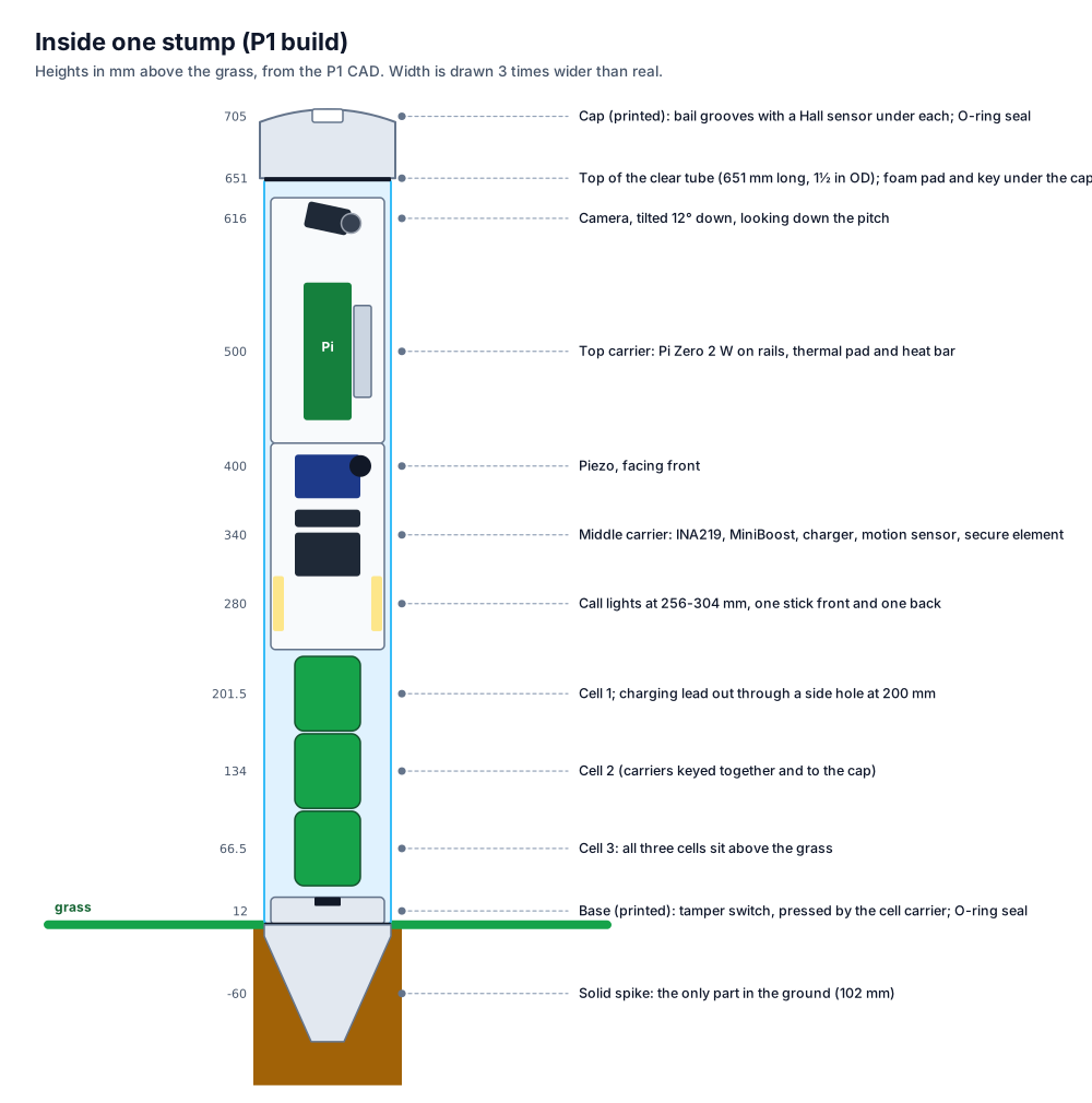
All six stumps are the same, apart from the cap:
- the middle stumps have two bail grooves and two Hall sensors;
- the outer stumps have one groove and one sensor.
The striker’s middle stump (computer name stump-sm) is also the brain: it collects what the other five see and makes the calls.
There is no umpire band. The umpire, scorer or captains see each call in the CricketOne app on their phone, and can get a buzz on their own smartwatch through the phone’s notifications. They answer unsure calls in the app.
2. The parts
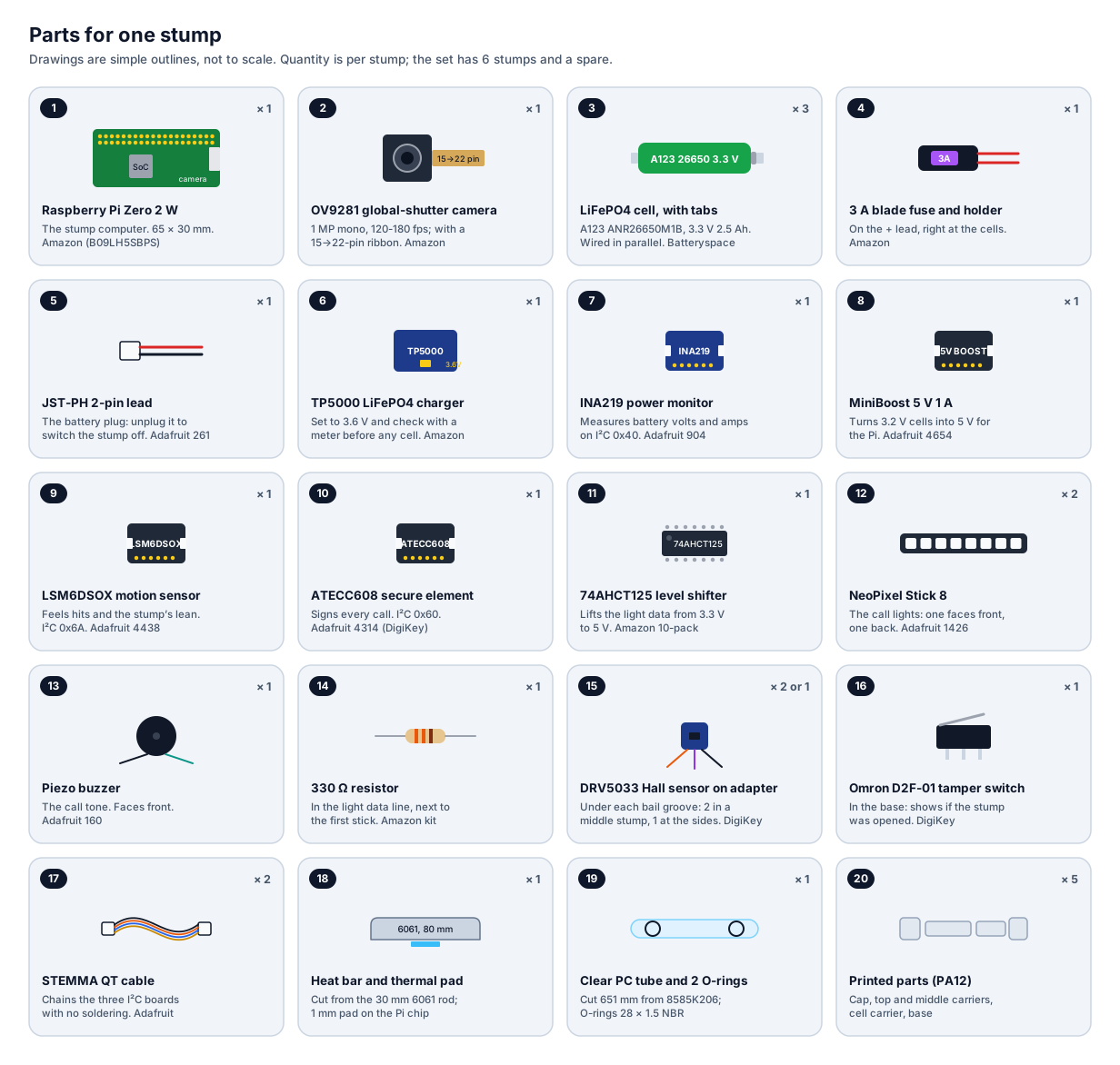
For each stump
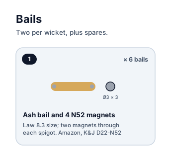
For the bails
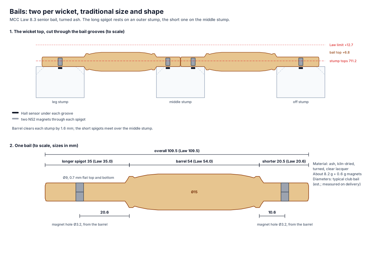
The bails
A wicket has two bails, never one long bar. Each is a traditional senior bail, sized to MCC Law 8.3: 109.5 mm overall, with a 54 mm barrel, a 35 mm longer spigot and a 20.6 mm shorter spigot.
The bail is turned ash, the traditional bail wood; P1 uses bought English ash bails. Our only change is a hole through each spigot for two small magnets, placed exactly over the sensor in the stump below. In production each spigot also gets a 0.7 mm flat on the top and bottom, so the bail settles magnet-down.
What the whole set needs
| Part | Per stump | Set (6 stumps + 1 spare) | Shop |
|---|---|---|---|
| Raspberry Pi Zero 2 W | 1 | 7 | Amazon |
| OV9281 camera (2-packs) and 15→22-pin ribbon | 1 | 8 cameras, 8 ribbons | Amazon |
| microSD 32 GB | 1 | 7 | Amazon |
| A123 26650 LiFePO4 cell, with tabs | 3 | 20 | Batteryspace |
| 3 A blade fuse and holder | 1 | 9 holders, 10 fuses | Amazon |
| JST-PH 2-pin lead | 1 | 14 | Adafruit |
| TP5000 charger board | 1 | 9 | Amazon |
| INA219 power monitor | 1 | 7 | Adafruit |
| MiniBoost 5 V | 1 | 7 | Adafruit |
| LSM6DSOX motion sensor | 1 | 7 | Adafruit |
| ATECC608 secure element | 1 | 7 | DigiKey |
| 74AHCT125 level shifter | 1 | 10 | Amazon |
| NeoPixel Stick 8 | 2 | 26 | Adafruit |
| Piezo buzzer | 1 | 14 | Adafruit |
| 330 Ω resistor | 1 | kit | Amazon |
| DRV5033 Hall sensor on a SOT-23 adapter | 2 or 1 | 15 sensors, 50 adapters | DigiKey, Amazon |
| Omron D2F-01 tamper switch | 1 | 15 | DigiKey |
| STEMMA QT cables | 2 | 20 | Adafruit |
| Heat bar (cut from 30 mm 6061 rod) and 1 mm thermal pad | 1 | 2 rods, 1 pad sheet | McMaster, Amazon |
| G-10 tube 651 mm (rev Q), O-rings 28 × 1.5, clear PC strip for the light slots | 1 tube, 2 O-rings, 2 strips | 42 in tube per stump (McMaster 6394A37), O-ring kit, 1/8 in PC sheet | McMaster, Amazon |
| Printed parts: cap, top carrier, middle carrier, cell carrier, base | 5 | 30 prints | print shop (Craftcloud) |
| Bails: English ash, Law 8.3 size, with four Ø3 × 3 mm N52 magnets each | 6 bails (3 pairs: 4 + 2 spare), 24 magnets | Amazon (FORTRESS Pro Bails), K&J |
3. Tools and safety
Tools, all in the Amazon cart:
- Pinecil soldering iron with its 65 W USB-C supply, solder, flux and desoldering wick;
- multimeter, wire stripper, flush cutters, calipers;
- helping hands, silicone mat, safety glasses;
- fine saw with a mitre box, and a deburring tool for the tube;
- epoxy, CA gel, VHB tape, zip ties, Kapton tape, isopropyl alcohol;
- XTAR LiFePO4 cell charger and tester, and a fire-safe battery bag.
Battery rules:
- Never solder onto a cell. Solder only to the cells’ tabs.
- Charge only between 0 and 45 °C, and never above 3.65 V a cell.
- Charge on the silicone mat or in the battery bag, and never leave cells charging alone.
- A cell that gets hot, swells, or reads below 2.5 V is recycled, never reused.
- Unplug the battery plug (JST) before you solder anything in a stump.
Before any cell goes near a TP5000 charger board:
- Set the board’s jumper to 3.6 V. It comes set to 4.2 V, which would overcharge a LiFePO4 cell.
- Power the board from USB with no cell connected.
- Measure the voltage across BAT+ and BAT−. It must read 3.55-3.65 V.
4. How it connects
4.1 Power: cells → fuse → plug → monitor → 5 V → Pi
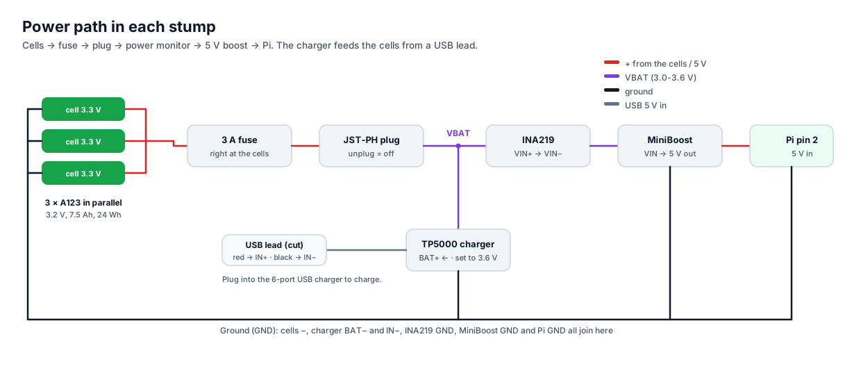
- Cells in parallel. Join all three + tabs with 22 AWG red wire, and all three − tabs with black. The pack stays at 3.2 V and holds 7.5 Ah (24 Wh).
- Fuse. The 3 A fuse holder goes on the + wire, right at the pack, so a short anywhere after it blows the fuse instead of burning a wire.
- Battery plug. A JST-PH 2-pin lead after the fuse. Unplugging it switches the stump off.
- VBAT. After the plug, + is called VBAT. Three things join it:
- the charger’s BAT+;
- the INA219’s VIN+;
- nothing else.
- Power monitor. INA219: VIN+ in, VIN− out. It measures the battery voltage and the current the stump draws.
- 5 V boost. INA219 VIN− goes to MiniBoost VIN. MiniBoost 5V goes to the Pi’s pin 2 and GND to pin 6. The MiniBoost gives up to 1 A. The Pi and camera use about 0.6 A, and the lights are capped in software at 25 % brightness (about 0.25 A).
- Charging (P1 only). Take a USB lead, keep the plug end and cut off the other end.
- Solder its red wire to the TP5000’s IN+ and its black wire to IN−.
- Bring the lead out through the side hole in the tube. To charge, plug it into the 6-port USB charger.
- In P2 the lead is replaced by sealed charge pads.
- Ground. Every − joins one ground: cells −, charger BAT− and IN−, INA219 GND, MiniBoost GND and Pi GND.
4.2 Signals: every wire to the Pi
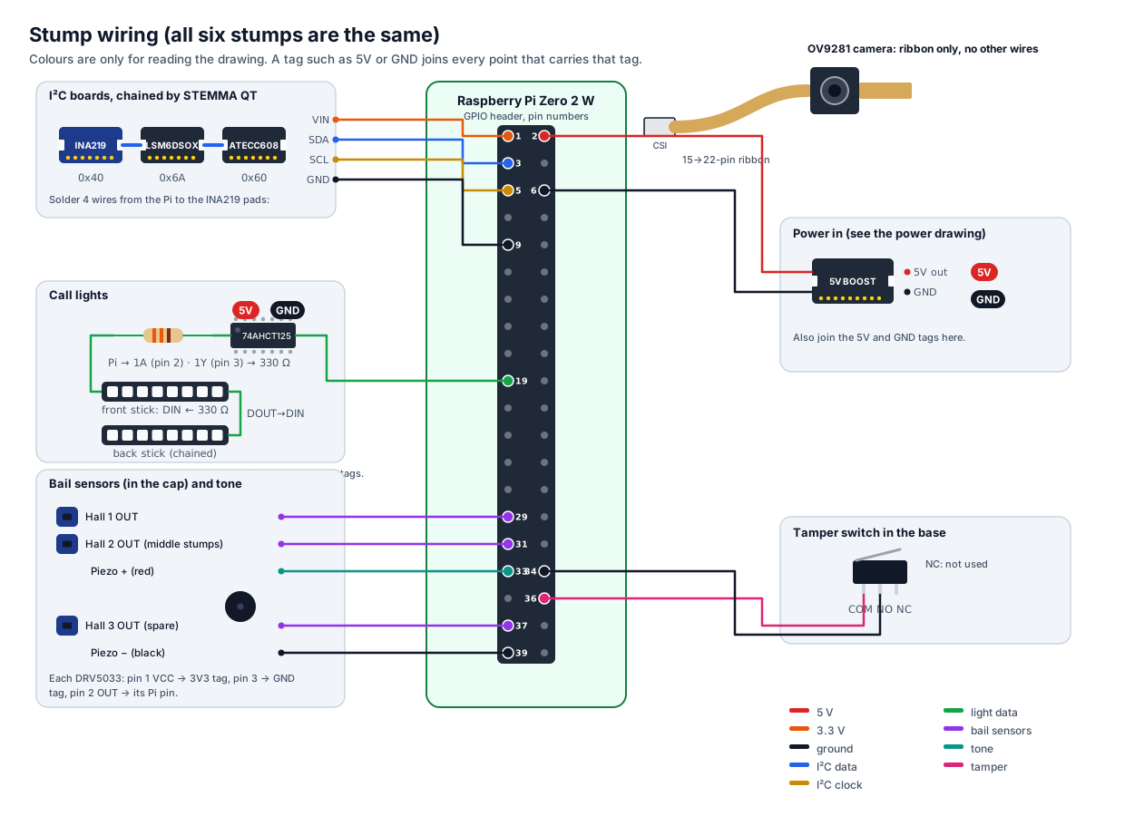
Wiring the GPIO header. The Pi Zero 2 W may come without a header. Inside the tube, solder the wires straight into the Pi’s holes; it is flatter and does not shake loose. Solder a header only on the bench-test Pi.
| Pi pin | Name | Goes to | Wire |
|---|---|---|---|
| 1 | 3V3 | INA219 VIN (feeds the whole I²C chain); each Hall sensor pin 1 | orange |
| 2 | 5V | MiniBoost 5V out; 74AHCT125 pin 14; both NeoPixel sticks 5V | red |
| 3 | GPIO2 SDA | INA219 SDA (I²C data) | blue |
| 5 | GPIO3 SCL | INA219 SCL (I²C clock) | yellow |
| 6, 9, 34, 39 | GND | MiniBoost GND, I²C GND, tamper NO, piezo −, Hall pin 3, 74AHCT125 pins 1 and 7, sticks GND | black |
| 19 | GPIO10 (SPI MOSI) | 74AHCT125 pin 2 (1A). Its pin 3 (1Y) → 330 Ω → front stick DIN | green |
| 29 | GPIO5 | Hall 1 OUT (pin 2) | purple |
| 31 | GPIO6 | Hall 2 OUT: middle stumps only | purple |
| 33 | GPIO13 (PWM) | piezo + | teal |
| 36 | GPIO16 | tamper switch COM | pink |
| 37 | GPIO26 | Hall 3 OUT: the Hall tamper in the base post (row Q15) | purple |
| camera | CSI connector | the 15→22-pin ribbon | ribbon |
On the Radxa ZERO 3W instead of the Pi (row R29): every wire stays on the same pin number except the two I²C wires: SDA goes to pin 27 and SCL to pin 28 (the Radxa’s pins 3 and 5 belong to its own USB-C chip). Its set-up turns on the pull-ups and the light’s SPI; python3 header.py prints the table.
The I²C boards (INA219, LSM6DSOX, ATECC608) all share the same four wires. Solder four wires from the Pi to the INA219, then chain the other two with STEMMA QT cables (plug-in, no soldering). Each board has its own address, so they don’t clash:
| Board | Address |
|---|---|
| INA219 | 0x40 |
| LSM6DSOX | 0x6A |
| ATECC608 | 0x60 |
The call lights need a 5 V data signal, and the Pi gives 3.3 V. The 74AHCT125 chip lifts it:
- Chip power: pin 14 to 5V; pins 1 and 7 to GND.
- Data in and out: the Pi’s pin 19 goes to chip pin 2. Chip pin 3 goes through the 330 Ω resistor to the front stick’s DIN.
- Second stick: chain the front stick’s DOUT to the back stick’s DIN.
- Unused pins: tie the chip’s other inputs (pins 5, 9, 12) to GND, and their enables (pins 4, 10, 13) to 5V.
The bail sensors (DRV5033, in SOT-23):
- Each sensor sits on a small adapter board. Pin 1 is VCC (3V3), pin 2 is OUT and pin 3 is GND.
- OUT is open-drain. The Pi’s own pull-up reads it high with no magnet and low when a bail magnet sits on it.
- Use thin 26 AWG silicone wire down the cap’s wire hole.
The camera needs only the ribbon:
- The 15-pin end goes into the camera and the 22-pin end into the Pi.
- At both ends, the metal contacts face the circuit board.
- Lift the connector’s latch, push the ribbon in straight, and close the latch.
4.3 How the parts fit in the tube
The G-10 tube (31.75 mm inside) is the stump’s wall. Everything else is one stack inside it:
| Part | Height (mm) | How it sits |
|---|---|---|
| Base (solid spike + plug) | −102 to 24 | the spike (−102 to 0) is the only part in the ground; the plug (0 to 24) pushes into the bottom of the tube on an O-ring |
| Cell carrier | 24 to 240 | stands on the base; its cross bar presses the tamper switch 0.8 mm |
| Middle carrier | 240 to 420 | stands on the cell carrier, keyed to it |
| Top carrier | 420 to 635 | stands on the middle carrier, keyed to it; a 1.6 mm foam pad on top |
| Cap | 636 to 711.2 | pushed into the top on an O-ring; its socket takes the top carrier’s key |
- Keys. One square key at each joint, off-centre, so each joint goes together only one way. The whole stack turns as one with the cap.
- Why that matters. The bails lie in the cap’s groove, along the wicket. So once the bails are on, the camera always faces down the pitch, however the round tube turns. The CAD checks that turning any part 3° makes it hit its neighbour.
- Front dot. A small dimple on the front of the cap shows which way the camera looks.
- No rattle. The parts stand on each other with no gap. The 1.0 mm gap under the cap is filled by a 1.6 mm adhesive foam pad, squeezed 38 %, which also takes up print tolerances.
- Wires. They run down the notches at the back of each disc. The Hall sensor wires leave the cap through a channel into its centre hole.
5. Build steps
Week 0: before the parts arrive
- Order the prints (PRINT.md, Craftcloud quote in REVIEW.md). Choose white for the stumps.
- Flash 7 microSD cards with Raspberry Pi Imager (section 6.1). Name them
stump-sl,stump-sm,stump-so(striker’s leg, middle, off),stump-fl,stump-fm,stump-fo(far end) andstump-spare.
Day 1: incoming check (about 2 hours)
- Tick every line of ORDER.md against the boxes: part number, quantity, damage.
- Cells:
- Measure every cell. A new LiFePO4 cell reads 3.2-3.3 V.
- Set aside any below 3.0 V.
- Top every cell up to full on the XTAR charger, so the three in each stump start equal.
- Camera:
- Measure one camera board and lens with calipers.
- Write the numbers into
build/cad/cricketone-p1-cad.mjs(the camera item), then rerun it.
- Pis: power each Pi Zero once from USB and check it boots and joins Wi-Fi.
- Chargers: set and check every TP5000 to 3.6 V (section 3).
Days 2-3: bench test B1 (camera first, then the tube’s camera hole and light slots)
Rev Q build (row Q12, 31 Oct 2026): the programs are in products/cricketone/software (its README has every command).
- On the bench Pi (with a header), connect one camera with the ribbon. Run
bash setup.sh, then reboot. - Run
rpicam-hello --list-cameras. It must list the ov9281. - Frame rate, always 8-bit. At 10 bits the sensor tops out at about 121 fps at 1280 × 800, so 120 has no margin; at 8 bits it reaches about 151.
bash b1_raw.sh: the camera alone, straight from the receiver. It must reach 119 fps for 6,000 frames.python3 b1_bench.py --no-encode, thenpython3 b1_bench.py(with the 720p30 clip), thenpython3 b1_bench.py --track. Each must reach 119 fps with no dropped frames; keep the threeb1-result.jsonfiles.- If the raw test passes and the others do not, the Pi’s image processor or our program is the limit, not the camera: try 1280 × 720.
- Film a ball dropped and a ball thrown about 2 m away with
python3 live.py --track. Check the ball is round and sharp in every frame. - The camera hole. Measure with calipers how far the lens front stands above the camera board’s face. It needs 7.5 mm or more (row R21, with the soft case’s corner windows), so the lens reaches to about 1 mm behind the tube wall (the top carrier holds it there). Drill a Ø10 hole in a G-10 offcut, hold the camera behind it as in the stump (lens 1 mm behind the inside wall, 1.6 mm above the hole’s centre) and run
python3 live.py. All four corners must be as bright as the middle. If they are dark, the lens is too short: write its height down; the hole grows instead (table in BRINGUP.md section 2, DESIGN.md “### R21”). - The light slots. Put a call light behind a 6 × 48 mm slot with its clear strip in a G-10 offcut. From 20 m in daylight, the green and red must be easy to tell apart.
- Wire one full stump on the bench, loose on the mat. Run the bring-up test until every step passes.
- Write the results into DESIGN.md as “B1 result”.
Day 3 onward: build one stump fully, then the other five (two a day)
1. Cut the tube.
- Cut 651 mm lengths in the mitre box, seven for the set.
- Square and deburr both ends.
- Tube (rev Q): the P1 wall is a G-10 glass-epoxy tube (McMaster 6394A37), not clear polycarbonate (too flexible and it crazes from alcohol and glue fumes). Cut it 651 mm. Mark the front line, then make these openings with a step drill and a fine file, wearing a dust mask (glass-fibre dust):
- a 4.4 × 3.5 mm notch in the top edge, on the front line, for the cap’s tab;
- a Ø10 mm camera hole on the front line, 616 mm from the bottom end;
- two 6 × 48 mm light slots, front and back, 256-304 mm from the bottom end, each with a clear polycarbonate strip glued in with epoxy (not CA);
- the charging-lead hole below.
- Charging-lead hole: drill a Ø6 mm hole 300 mm from the bottom end (300 mm above the grass, beside the charger on the middle carrier, clear of the cells), using a step drill and light pressure. Smooth it, and later seal round the lead with a bead of silicone. The base and its solid spike close the bottom end, so the lead cannot leave through the bottom.
2. Cap.
- Glue each DRV5033 onto an adapter board and solder three wires (VCC, OUT, GND).
- Seat the board in its pocket under the bail groove, chip face up, and fix it with a drop of epoxy.
- Run the wires down each sensor’s small hole, along the cross channel and out of the centre hole, about 150 mm long. Fit the O-ring.
3. Base.
- Press the tamper switch into its pocket, lever up.
- Solder COM and NO wires, 700 mm long (they run up to the Pi).
- Fit the O-ring.
4. Cell carrier.
- Wire the three cells in parallel with the fuse and the JST plug (section 4.1).
- Slide them into the carrier and bring the leads up the back channel.
- Measure 3.2-3.4 V at the plug.
5. Middle carrier.
- Stick the TP5000, INA219, MiniBoost, LSM6DSOX and ATECC608 to the deck with VHB tape. Add zip ties through the slots.
- Mount the two NeoPixel sticks back to back at 256-304 mm: one faces front, one faces back.
- Mount the piezo facing front.
- Wire the power path, the I²C chain, the level shifter and the lights.
6. Top carrier.
- Slide the Pi between the rails.
- Put a 1 mm thermal pad on the Pi’s chip, then the aluminium heat bar on its two seats. The bar (R17) is an 80 mm piece of the 30 mm rod with three flats filed or milled: two sides 16 mm apart and a back face 3.5 mm in front of the rod’s centre (11.5 mm to the round face); leave the front round. Drill both ends of the bar 2.5 mm, 9 mm deep, on the centre line 6 mm in from the back face (9.5 mm from the rod’s centre), and tap them M3 (R19). Stick a 16 × 80 mm strip of the TP-3 pad on the round face, cover it with one layer of Kapton tape, and cut both strip ends at 45° so they slide in. In the tube the strip meets the wall through the window in the top sleeve. Lay the bar on its seats between the two bridges and fit an M3 x 16 screw down through each bridge into the bar’s ends; tighten by hand with a hex key (snug, about 0.5 N·m), bottom screw first, before the camera goes on its bracket.
- Bolt the camera to the tilted bracket with M2 screws, lens facing the front (away from the deck).
- Plug in the ribbon.
7. Test before closing.
- With the stack outside the tube, plug in the battery.
- Run
stump-bringup.py. Fix anything that fails now, while every wire is easy to reach.
8. Stack and close. The G-10 tube is not clear: join the carriers outside the tube so you can see every key go in, and line the cap’s tab up with the notch so the camera faces its hole.
- Base: feed the tamper wires up through the tube and out of the top. Push the base into the bottom until its shoulder meets the tube.
- Charging lead: push its cut end in through the side hole and out of the top of the tube.
- Join the carriers outside the tube: cell carrier → middle carrier → top carrier. Each key drops into its slot; turn the part until it does.
- Connect the tamper wires, the charging lead (to the TP5000) and the cap’s Hall wires to the stack.
- Lower the stack in from the top, cells first. Pull the spare lead back out through the side hole as it goes. The cell carrier stops on the base and presses the tamper switch.
- Foam pad: cut a Ø30 mm disc from a 1/16 in foam square, with a 5 mm hole for the key. Stick it on the top carrier’s disc.
- Cap: push it into the top, turning it until its socket drops over the top carrier’s key, then press until its shoulder meets the tube. The dot on the cap now shows the camera’s side.
- Charge through the lead.
9. Soak.
- Number the stump on its cap.
- Leave it running for 2 hours with the camera and finder on:
python3 soak.py --load "python3 live.py --track"(row R8). Every minute it logs the cell voltage and current, the power, the Pi temperature, its throttle flags and the boot id, and at the end it prints the pass marks: cells never below 3.00 V, the Pi at or below 75 °C with no throttle or under-voltage flag, no reboot, and a run time that covers a T20 evening (3.5 h) for new and old cells. Expect about 2.9 W and 5.8 Wh (est., docs/DESIGN.md “### R8”). Keepsoak-log.jsonlandsoak-result.json. - Plug the charger in and run
python3 soak.py --charge: the cells must never pass 3.65 V and the charge must end (below 50 mA), in about 1.7 h.
10. Knock and drop (row R9). Only on turf or a 20 mm gym mat, never on a hard floor.
- Run
python3 drop_test.py --selftest(must printall pass), thenpython3 drop_test.pyand leave it running. - Tap the standing stump with a bat handle: a
knockline and nothing else. If no knock line comes, the motion sensor’s wake-up flag is not set up: stop and send back the output. - Do the steps in this order, five times each, waiting about 65 s after each one for its line (the program checks the cells a minute later). Stop at the first FAIL.
- D1: hold the stump flat at 0.5 m over the mat and let go. The line should say
flat dropand about 0.5 m. - D2: push the stump in the ground over so it falls flat on the turf. The line should say
tip-over. - D3: a flat drop from 0.5 m onto turf. D4: from 1.0 m onto turf. These go past the cells’ rated shock (docs/DESIGN.md “### R9”), so do them only after D1 and D2 pass, and look at the cells (no swelling, no smell) after each one.
- D1: hold the stump flat at 0.5 m over the mat and let go. The line should say
- Each line must say
PASS: a camera frame within 250 ms, no reset, no tamper alarm, and the cells within 10 mV a minute later. Press Ctrl-C and keepdrop-result.json. - After the session: a torch behind the G-10 shows no crack or white patch, the cap screw is tight, and the core still pulls out on its cord.
11. Ball hits, T1 (row R10). Only after steps 1-10 pass, with a borrowed or hired bowling machine; nothing is booked.
- Wrap a strip of bright tape round the stump 295 mm up (its balance point) and round a plain ash stump 327 mm up. Set a phone side-on at 240 fps slow motion, about 2 m away, with the whole stump and the last metre of the ball’s path in the frame.
- Run
python3 t1_test.py --selftestandpython3 guard.py --selftest(both must printall pass), thenpython3 t1_test.pyand leave it running. It prints the next hit after each line. - Fire the hits in its order (30 m/s first, cap height last), waiting about 65 s after each one for its line. Each must say
PASS: no reset, the camera back within 250 ms, one knock and no tamper alarm, the cells within 10 mV. Stop at the first FAIL. - Film each hit, and the ash stump hit the same way once per step. Track the ball and the tape in any video tool into a CSV (frame, ball x, tape x, and
# px_per_mm=from the 711 mm stump), thenpython3 t1_test.py --video hitNN.csv --hit NN --ash ashNN.csvjudges mark 5. - After the session: the card passes a file check, a torch behind the G-10 shows no crack or white patch, the cap screw is tight, and the core still pulls out on its cord. Keep
t1-result.jsonand the films.
Day 8: the bails (about 1 hour for 6)
- Measure each bail with calipers. Write down the overall length (Law: 109.5 mm), the barrel (54.0), the long spigot (35.0), the short spigot (20.6) and the spigot diameter.
- If the spigot is not Ø9, set
BOUGHT.spigotDinbuild/cad/cricketone-p1-cad.mjs, rerun it and print the two collars.
- If the spigot is not Ø9, set
- Drill the long spigot.
- Slide the long collar onto the long spigot until it stops against the barrel, then lay it on its flat side.
- Drill straight down through the guide hole and right through the spigot with the 3.2 mm bit in the pin vise.
- Drill the short spigot the same way, with the short collar.
- Fit the magnets.
- Stack two magnets (they snap together). Keep one spare magnet as a tester, with one face marked: the face of each stack that the tester’s marked face pulls toward is the face that goes down. Mark it.
- Push the stack into the hole, marked face down, until it sits 0.8 mm in from both faces.
- Fill both ends of the hole with a drop of 5-minute epoxy, level with the wood. Use the same pole down on every bail.
- Check the bail on a built wicket. Lay it with the long spigot on an outer stump and the short spigot on the middle stump. Run
stump-bringup.pyand check both sensors see it. - Time the bail-off (row R8). Run
python3 bail_test.py --selftest(must printall pass), thenpython3 bail_test.py. Film the bails at 240 fps with a phone and knock each bail off 10 times with a bat handle (20 in all). For each one, count the frames from the bail’s last touch to the red light. Thenpython3 bail_test.py --report bail-log.jsonl --video-frames 3,4,...(one number per bail-off, in order). Pass: median at most 19.6 ms and none over 86.1 ms. Keepbail-result.json.
6. Install the software
6.1 SD cards (on your laptop)
- Install Raspberry Pi Imager from raspberrypi.com/software.
- Choose the device Raspberry Pi Zero 2 W and the OS Raspberry Pi OS Lite (64-bit).
- Click Edit settings and set:
- hostname:
stump-sm(or the stump’s name); - username and password: your own;
- Wi-Fi: the club Wi-Fi or a phone hotspot, with country US;
- SSH: turned on in the Services tab.
- hostname:
- Write the card. Repeat for all seven cards, changing only the hostname.
6.2 Stump setup (on each Pi)
- Put the card in the Pi and power it.
- From your laptop, connect with
ssh [email protected]. - Run:
curl -fsSLO https://iemilabs.com/downloads/cricketone/install-stump.sh
sudo bash install-stump.sh
sudo reboot
The script does five things:
- Camera, I²C and SPI: turns them on in
config.txt(dtoverlay=ov9281,arducam). - Drivers and tools: installs the camera tools (
rpicam-apps,picamera2) and the GPIO and I²C tools. - Board libraries: installs the Adafruit libraries for the INA219, the LSM6DSOX and the lights, in
/opt/cricketone/venv. - Wi-Fi power saving: turns it off, for steadier timing.
- Clock sync: sets up chrony, so the five other stumps follow the clock of
stump-sm.
If the camera is not found:
- Check the ribbon first.
- Then try removing
,arducamfrom the overlay line in/boot/firmware/config.txtand reboot.
6.3 Bring-up test (on each Pi)
/opt/cricketone/venv/bin/python /opt/cricketone/stump-bringup.pyThe test checks each part in turn and prints PASS, FAIL or INFO. It asks you to do things along the way: put a magnet on each bail sensor, press the tamper switch, and say whether you saw the lights and heard the tone. Use --quick to read the sensors without questions.
| Step | Pass means | If it fails, check |
|---|---|---|
| Camera found | ov9281 listed | the ribbon direction at both ends, then the overlay line |
| Camera 1280 × 800 @ 120 | at least 115 fps | power (a weak 5 V drops frames); the Pi temperature |
| I²C boards | 0x40, 0x6A and 0x60 answer | 3V3 on pin 1, SDA on pin 3, SCL on pin 5, and the STEMMA QT plugs |
| Battery voltage | 2.9-3.65 V | the fuse, the JST plug, and the cells |
| Motion sensor | about 9.8 m/s² in total | the board is tight on the deck |
| Bail sensors | the reading changes with a magnet | VCC to 3V3, OUT to the right pin; the chip faces up |
| Tamper switch | closes when pressed | COM to pin 36, NO to GND |
| Call lights | red, green, blue, white on both sticks | 5V on chip pin 14, the 330 Ω, DIN (not DOUT) at the first stick |
| Call tone | two beeps | piezo + on pin 33 |
6.4 The match software
The software that tracks the ball and makes the calls (iemi-stump, plus the app) is being written now, in phase 3. Each piece is tested in our simulations first (products/cricketone/sim), then on the bench. When it is ready, it installs over this setup with one command, and this page will give that command. Until then, the bring-up test above proves the hardware.
7. How a call is made: the software and the models
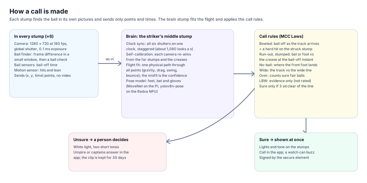
| Job | How it is done | Software or model | Runs on |
|---|---|---|---|
| Take sharp pictures of a 90 mph ball | Global-shutter camera, 0.1 ms exposure, 1280 × 720 at 180 fps (1280 × 800 at 120 fps at the least) | Linux camera driver ov9282/ov9281, libcamera, picamera2 |
each stump |
| Find the ball | Compares each frame with the last one in a small window where the ball should be, then checks the blob is ball-shaped. Sends only (x, y, time) points, never video | our code (OpenCV-style image maths); a small ball-check network on the Radxa’s NPU in P2 | each stump |
| Put six cameras on one clock | Keeps the fastest of 16 Wi-Fi time exchanges a second, fits each crystal’s drift, then a light-flash check between the wickets | chrony now; our filtered sync and a real-time Linux kernel next (simulated at 0.005 ms) | all stumps; stump-sm is the clock |
| Know exactly where each camera points | Finds the far stumps (sizes fixed by Law 8) and the creases in half a second of frames, plus the stump’s lean from the motion sensor | our self-calibration (camera resectioning) | each stump |
| Know when a bail comes off | Hall sensor under each groove; the moment the magnet leaves | GPIO edge time stamps on the synced clock | each stump |
| Rebuild the ball’s flight | Fits one physical path through every point from all six cameras: gravity, air drag, swing, the bounce. How badly it fits is the confidence | our flight fit (weighted least squares) | the brain, stump-sm |
| Find feet, bat and gloves | A pose model finds body keypoints for no-balls, run-outs, stumpings and hit wicket | MoveNet Lightning (TensorFlow Lite) on the Pi; yolov8n-pose (INT8, RKNN) on the Radxa NPU in P2 | stumps facing the play |
| Decide the call | The MCC Law for each call, checked against the measurements (table below). A call is sure only if the measurement is at least 3 standard deviations clear of the line; otherwise it is unsure and a person decides | our call rules | the brain |
| Prove the call is genuine | Every call, with its clip and sensor times, is signed into a chained log the app can check | ATECC608 secure element (ECDSA P-256) | every stump |
| Show the call | Lights and tone on the stumps, and the call in the app; the phone can buzz a smartwatch | NeoPixel lights, piezo, MQTT to the app | stumps, phone |
The calls and their rules (club play)
| Call | What decides it | Sure in our simulations | When unsure |
|---|---|---|---|
| Bowled | a bail comes off as the ball’s track reaches the stumps, with a hard hit on the struck stump | 97.5 % of bowled balls, no wrong sure calls | the clip goes to the umpire |
| Run-out, stumped | where the bat or foot is against the crease at the instant the bail comes off | ±6.5 mm (run-out), ±2.8 mm (stumped) at 95 % | the umpire decides |
| Front-foot no-ball | where the front foot lands against the popping crease | ±2.6 mm at 95 % | the umpire decides |
| Wide | the ball’s track against the league’s wide line | sure on 83 % of leg-side balls, none wrong | the umpire decides |
| Over complete | counts only sure, fair balls | right on 99.4 % of overs | “check count”: the captains answer in the app |
| LBW | ball track: where it pitched, where it hit, where it was going | not rated until field tests | always evidence only; the umpire decides |
All these numbers come from our simulations (products/cricketone/sim), not from matches yet. The field tests (B2, B3, T1-T10 in DESIGN.md) will measure them. In league games the stumps only assist the umpires, unless the league chooses otherwise.
A known P1 limit. The P1 bail sensors are DRV5033 switches. Our bail-off study (row P18) found a switch lets go up to 11 ms late (median), because the strong magnet holds it on until the bail has lifted a few mm. That is fine for the bench tests and for bowled, but too slow for close run-outs. P2 changes to a DRV5055 linear sensor with an ADS7142 converter: same size, same place, within 0.3 ms.
8. Troubleshooting
| What you see | Most likely cause | Fix |
|---|---|---|
| Pi does not boot from the battery, but does from USB | the MiniBoost is not getting VBAT, or the fuse has blown | measure 3.2 V at INA219 VIN−, then 5 V at MiniBoost 5V |
| Pi reboots when the lights flash | 5 V sags | keep the brightness at 25 %; check the MiniBoost GND to pin 6 |
| Only the first stick lights | DOUT → DIN link missing | wire the front stick’s DOUT to the back stick’s DIN |
| Lights flicker or show random colours | data at 3.3 V, or no common ground | route the data through the 74AHCT125; join the sticks’ GND to the Pi GND |
| A bail sensor always reads “magnet” | OUT shorted to GND, or the chip is upside down | check the adapter board solder; the chip text faces up |
| Camera listed, but frames drop | the ribbon is loose or the Pi is hot | reseat the ribbon; check the thermal pad and the heat bar |
| Cells get warm while charging | the charger is set to 4.2 V | unplug now; set the jumper to 3.6 V and measure again |
9. After P1: what changes in P2
| P1 (hand-built) | P2 (designed board) |
|---|---|
| Separate charger, boost, monitor and motion boards | one IEMI power board (TI BQ25070 charger, TPS61023 boost, LSM6DSOX) |
| DRV5033 bail switches | DRV5055 linear sensors and an ADS7142 window ADC (bail-off within 0.3 ms) |
| Pi Zero 2 W | Radxa ZERO 3W with an NPU (about 7× faster pose model), if bench test B1 passes |
| USB lead for charging | sealed charge pads and a 6-bay charging case |
| Clear polycarbonate tube | glass-fibre tube with glass camera windows, for ball-cannon strength |
Files
- Stump setup: install-stump.sh
- Stump bring-up test: stump-bringup.py
- How to use the finished set: CricketOne user manual
- In the repository, under
products/cricketone:- print files:
build/cad/stl/; - print table:
build/PRINT.md; - drawings source:
build/figures/make-figures.mjs.
- print files: