AisleOne: circuit boards of our own
What changed (4 Nov 2026). The rev A bench aisle is built from bought boards joined by leads and ribbons: a Raspberry Pi 5 in each canopy, two Camera Module 3 Wide boards on 1 m ribbons at x ±915, four NeoPixel sticks, a piezo, an ATECC608 board, a plunger tamper switch and a potted IRM-20-5 on flying leads. AisleOne now gets boards of our own, like CricketOne, on our board platform. The same set goes in both runs: run A’s merges the aisle and keeps the task list; run B’s, turned round, sends its calls to run A over the store Wi-Fi.
- The chips: the V2 core (Rockchip RK3576J, 2 GB LPDDR4X, 16 GB eMMC, AMPAK AP6275S Wi-Fi 6/BT module), two bare Sony IMX577 12 MP camera chips under M12 lens holders (the C1 camera on the board), 72 RGB call-light LEDs, an SMD piezo, the security chip, a Hall tamper switch and a PCB-mount Mean Well IRM-20-5.
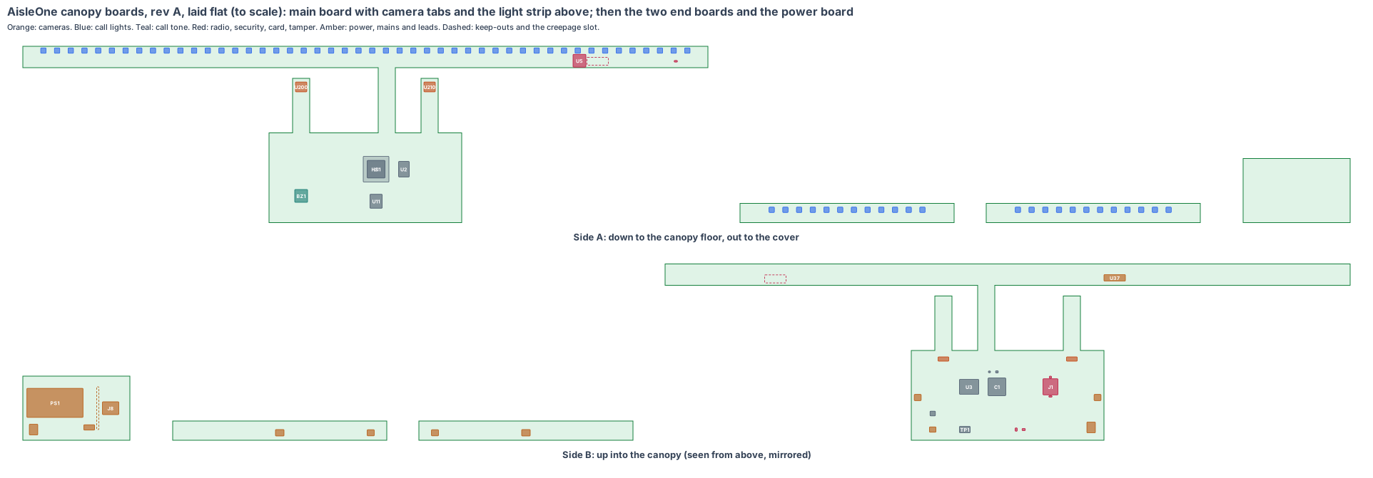
- The shape: in each canopy, one rigid-flex piece: an 8-layer main board (180 × 84 mm) flat on the canopy floor at the middle of the run; two 16 × 16 mm camera tabs on 35 mm flex hinges off its front edge, each held on its camera’s axis by a printed bracket; a 4-layer light strip (640 × 20 mm) standing 4 mm behind the opal cover on a 16 mm flex (F1). Two 2-layer end light boards (200 × 18 mm) behind the cover at x ±1,400 on latched leads, and a 2-layer power board (100 × 60 mm) at the back of the canopy floor with the mains terminal and the supply.
- The cameras move to the middle (fixed): a camera chip must be a short flex from the processor, not a 1 m ribbon, so both cameras now sit at x ±60, turned 30° out to the aisle ends and 30° down. The CAD’s view check shows every one of the 28 calls still in view (rev T CAD, the same day).
- A bigger camera chip (fixed): from the middle, the farthest price label (the opposite top shelf at the aisle end) is 2.7 m away. The 8 MP IMX415 under a 102° lens gave its digits 6.4 px, under the 8 px the label reader needs. Every call sits within 34.8° across and 28.5° up-down of the camera’s axis, so a 4:3 12 MP IMX577 under an 80° lens covers them all and gives the digits 8.6 px (to prove on rev A).
- Made from the shared rules: MEMS clocks, the latched microSD card with our software on every board, conformal coating, the antenna checked for the aluminium canopy on rev A, cameras 30 mm or more from the processor, the lens chosen from the calls and its front just inside the cover (lesson: window).
The bench canopies stay the test rig until the boards arrive.
1. The shape: five boards per run
| Piece | Size | Layers | Where | What |
|---|---|---|---|---|
| Main board | 180 × 84 mm, 1.6 mm | 8 | flat in the canopy, side A 10 mm over the aluminium floor, at the middle of the run | the V2 core, card, security, call tone, camera supplies, LED line driver, power and light headers |
| Camera tabs (2) | 16 × 16 mm, 0.8 mm, on 35 mm flex hinges | 8 | off the main board’s front edge at x ±60, turned 30° out and 30° down | IMX577 and M12 lens holder each, lens front 0.5 mm inside the cover’s face |
| Light strip | 640 × 20 mm, 1.6 mm | 4 | standing 4 mm behind the opal cover above the camera windows, on F1 (70 mm) | 48 call-light LEDs, Wi-Fi/BT module, cover tamper switch |
| End light boards (2) | 200 × 18 mm, 1.6 mm | 2 | standing 4 mm behind the cover at x ±1,400 | 12 call-light LEDs, latched 3-pin header, polyfuse |
| Power board | 100 × 60 mm, 1.6 mm | 2 | on 6 mm stand-offs at the back of the canopy floor, x −330 to −230 | push-in mains terminal, fuse and varistor, IRM-20-5, creepage slot, latched 2-pin header |
Leads: L1 (power board to main board, 5 V, about 0.5 m of 18 AWG, Molex Micro-Fit 3.0 2-pin latched); L2 and L3 (main board to the end boards, about 1.4 m of 24 AWG each, JST GH 3-pin latched: 5 V, GND, LED data), along the canopy floor.
2. What is on the boards
Main board, side A (down, to the canopy floor): RK3576J (U1) with a 24 × 24 aluminium heat block and gap pads to the canopy floor (HS1), LPDDR4X (U2), eMMC (U11), the SMD piezo (BZ1) over the tone holes.
Main board, side B (up): the RK3576J decoupling field (C1), RK806S power (U3), 24 MHz and 32 kHz MEMS oscillators (Y1, Y2), ATECC608B (U8) and the ID chip (U9, which also says run A or B), the latched microSD socket (J1), reached by taking off the canopy cover, the eFuse (U42), the latched power header (J2) and light headers (J3, J5), the SN74AHCT125 line driver (U36), the camera supplies (U21, U22) and the factory pads (TP1).
Camera tabs: an IMX577 (U200, U210) under an M12 lens holder with an 80° × 64.4° lens (LH1, LH2) on each, turned 30° out and 30° down at the opposite run and the floor; people are masked out of every still, never faces.
Light strip, side A (to the cover): 48 WS2812B-class LEDs at 12.8 mm pitch (D1–D48: amber for a restock or a label, red for a spill or a person down, green when cleared), the AP6275S Wi-Fi/BT module (U5) with its antenna keep-out (ANT1) behind the opal, the DRV5032 cover tamper switch (U7) under a magnet in the cover. Side B: the call lights’ power and 1 A limit (U37).
End light boards: 12 WS2812B-class LEDs each (DL1–DL12, DR1–DR12), the latched 3-pin header (J6, J7) and a polyfuse with bulk capacitor (C8, C9).
Power board: the push-in 3-pole mains terminal (J8) for the canopy light feed, a 1 A slow-blow fuse and a varistor (F1A), the IRM-20-5 (PS1), a milled creepage slot (SLOT) and the latched 5 V header (J9).
3. Every connection, checked
| Link | How | Checked against |
|---|---|---|
| Camera chips to RK3576J | 4-lane MIPI CSI-2 each, across the 35 mm flex hinges | IMX577: 4056 × 3040 at 30 fps; at 2 fps each uses 0.25 Gbps of its link (est. 1.5 Gbps per lane, data sheet to read) |
| Call lights | one data line up F1; two over L2 and L3 through a 3.3 → 5 V line driver | WS2812B data sheet; TI SN74AHCT125 |
| Wi-Fi/BT | SDIO and UART up F1 | AMPAK AP6275S (RK3576 SDK default) |
| Call tone | PWM from the RK3576J through a small driver to the piezo | PUI Audio AT-1220 class (est.) |
| Run B to run A | the store’s WPA3 Wi-Fi; every call signed by the sending run’s security chip | AP6275S; ATECC608B |
| Power in | canopy light feed (120 or 230 V) into the push-in terminal, fuse, varistor, IRM-20-5 (Class II); L1 drops 0.05 V at 2.4 A | Mean Well IRM-20 data sheet |
| Card | SD bus to the RK3576J, latched socket | Amphenol 101-00660 family drawing |
Every mating pair is checked against the makers’ documents, never “same as” another board.
4. Heat
The 3.66 m aluminium canopy is the heat sink: about 3 W from the RK3576J goes through the heat block into the canopy floor (4 K/W est.), so the chip sits near 50 °C with the canopy at 38 °C under the store lights. The IRM-20-5 sits 240 mm from the processor at the back of the canopy. The camera chips are 86 mm and 72 mm from the processor.
5. Power budget per run (est.)
| State | Draw |
|---|---|
| Open hours: floor check 2 fps, a still every 10 min (RK3576J, two cameras, Wi-Fi) | 4.1 W |
| Call lights at 10 %, security, tone idle | 1.4 W |
| Spill call: middle strip at its 1 A limit, end boards at 0.4 A each, tone | up to 9.5 W |
| Peak | 9.5 W, 68 % of the 14 W allowed (20 W supply) |
| Closed: tamper and after-hours watch, processor mostly asleep | 1.5 W |
6. Factory test (every board, every time)
Spring-pin fixture on TP1 and the small boards’ pads: 5 V in on L1, the eFuse trip at 3.5 A, every rail, boot from the card, a frame of a test chart from each camera, all 72 LEDs, the piezo against a sound-level meter, the tamper switch with a magnet, the security chip’s key, the ID chip set to run A or B. The power board is tested on its own behind an isolating transformer: hi-pot across the slot, 5 V under load.
7. Who makes what
One maker makes the rigid-flex piece and the three small boards and assembles them (turnkey), and makes the three leads to length. We supply the microSD cards with our software and the lenses focused at 2.5 m (est.). The quote pack is /build/aisleone-quote.
8. Cost per aisle, electronics (est.)
| Item | Per run | Per aisle |
|---|---|---|
| V2 core (RK3576J, LPDDR4X, eMMC, power, AP6275S) | $42 | $84 |
| Two IMX577 camera chips, holders and lenses | $36 | $72 |
| 72 LEDs, line driver and their power | $7 | $14 |
| Piezo, security, ID, Hall switch, eFuse, socket, passives | $6 | $12 |
| IRM-20-5, mains terminal, fuse, varistor | $14 | $28 |
| Boards (8-layer rigid-flex with a 640 mm strip, three small boards), 1,000 runs | $26 | $52 |
| Three leads | $4 | $8 |
| Assembly and test | $12 | $24 |
| microSD card with our software | $4 | $8 |
| Total | about $151 | about $302 (est.) |
The bench canopies’ bought boards cost about $480 per aisle at qty 1 (two Pi 5s, four Camera Module 3 Wide boards, eight NeoPixel sticks and the small boards), so our boards are about $180 cheaper per aisle at 1,000 (est.).
9. Timeline
| Step | When |
|---|---|
| Shape and placement (this page) | done, 4 Nov 2026 |
| Rev T CAD: cameras and windows at the middle of each run, tone holes under the board (drawn the same day); camera brackets, magnet pocket and the board set in the CAD next | next |
| Schematic, footprints, routing | Dec 2026 – Jan 2027 |
| Rev A boards made and tested in one aisle | Mar 2027 (est.) |
10. Still to check
- The IMX577’s package, supplies and lane rate from Sony’s data sheet, and its driver in Rockchip’s RK3576 SDK (est. until read).
- The 80° lens for a 1/2.3-type chip: its real view and sharpness at 2.7 m, and the label digits on rev A (8.6 px against 8 needed).
- Wi-Fi range from inside the aluminium canopy, run B to run A across the aisle (antenna behind the opal).
- The power board’s creepage and clearance once routed (IEC 62368-1), UL 962 for the gondola with its light feed.
- The 640 mm light strip’s panel length and the F1 SDIO impedance with the maker.
Sources
- Rockchip RK3576 brief: https://www.rock-chips.com/a/en/products/RK35_Series/2024/0524/1977.html
- Sony IMX577 (12.3 MP, 1/2.3-type): https://www.sony-semicon.com/en/products/is/industry/index.html
- AMPAK AP6275S: https://www.ampak.com.tw/
- Mean Well IRM-20 data sheet: https://www.meanwell.com/Upload/PDF/IRM-20/IRM-20-SPEC.PDF
- Worldsemi WS2812B: http://www.world-semi.com/
- TI SN74AHCT125: https://www.ti.com/product/SN74AHCT125
- Microchip ATECC608B: https://www.microchip.com/en-us/product/atecc608b
- TI DRV5032: https://www.ti.com/product/DRV5032
- The aisle: products/aisleone/cad/aisleone-cad.mjs (rev A, cameras, windows and tone holes rev T); the boards: products/aisleone/hardware/pcb/aisleone-board.mjs
Design review (4 Nov 2026)
Every board is checked by the same rules (products/_shared/board-rules.mjs), one for each lesson any of our boards has taught us. AisleOne’s boards were made with every rule from the start: 15 pass, 4 fixed, 13 to prove, 0 fail. The full review, with every number and its source, is on the board page. It shows:
- The cameras a short flex from the processor (fixed): both move from the 1 m ribbons at x ±915 to the middle of the run, turned 30° out; every one of the 28 calls stays in view, the worst at 34.8° across and 28.5° up-down. Drawn in the CAD the same day.
- The farthest price label (fixed): from the middle, the label at the far aisle end is 2.7 m away; the 8 MP chip under 102° gave 6.4 px, so the board takes a 12 MP 4:3 chip under an 80° lens: 8.6 px against 8, little spare, so it is proved on rev A.
- Camera windows: the floor at the aisle end is the steepest line of sight (71° from the cover), so each 33 × 34 window opens outward from its axis (lesson: window).
- The latched microSD (J1) is fitted, and our software starts from it; updates run only when the store is closed.
- Conformal coating on all five boards, the power board’s mains side included.
- Fast lines on a solid ground plane (to prove, lesson: planes, from the CricketOne test-board layout of 4 Nov 2026): RK3576J memory; 2 camera MIPI links (100 Ω pairs); USB (90 Ω); antenna feed (50 Ω, keep-out on every layer); card lines (length-matched, no vias under the socket). Ground on the layer next to the parts (inner layer 1, supply on inner layer 2; the whole bottom of a 2-layer section), one via beside each ground and supply pad and none in pads, no copper or vias in the antenna keep-out on any layer or under the card socket, the impedance lines routed first with a test coupon. The quote asks for it; the routed board’s design rule check proves it.
- To prove on rev A: the label digits, the AI time per check, Wi-Fi from inside the canopy, the camera brackets, the call lights through the opal, the mains creepage, the tamper magnet, the flex and the boards in the rev T CAD.
The request for quote is /build/aisleone-quote.