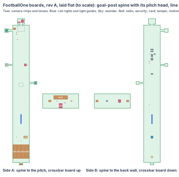
FootballOne: one circuit board of our own up every goal post, and one in each crossbar
The two goals are the product. Each post now carries one board of our own with every chip soldered on it, shaped as a spine that stands up the inside of the 120 × 100 × 3 aluminium oval post (114 × 94 bore). The same board fits all four posts. Each crossbar carries a small second board. The bench build used a Raspberry Pi Zero 2 W and a Raspberry Pi AI Camera in each post, a XIAO ESP32-S3 Sense goal-line camera, a PowerBoost charger, and a XIAO nRF52840 in the crossbar, joined by leads; all of that becomes two board designs.
| Board | Core (products/PCB-PLATFORM.md) | Where |
|---|---|---|
| Goal-post board (×4 a pair) | V1 (RV1126B) + two C1 camera chips | a spine up each post, 1,560 to 2,320 mm, 25 mm towards the back face |
| Crossbar board (×2 a pair) | S1 (ESP32-S3 module) | flat in the middle of each crossbar, 12 mm below its axis |
Why the goal-line camera moved. The bench goal-line camera sat 1.22 m up. On our own board its chip must be a short flex from the processor (camera lanes do not run a metre), so the window moves up to 2.0 m and the camera tilts 10° down. It still sees the ball on the ground at the middle of the line, the far post up to the crossbar and the goal line 16.5 m beyond the far post (rev T CAD, 4 Nov 2026).
1. The shape
Goal-post board. An 8-layer spine, 92 × 760 mm, side A to the pitch, side B to the back wall (21 mm of room on side B, 71 mm on side A at the middle; every part’s corners are checked against the oval in 3D). Five pieces bend off it:
- Pitch head: a 20 × 20 mm head on a flex (about 40 mm, est.), its face tilted 15° down to the pitch. The Sony IMX415 camera chip sits under an M12 lens whose front is just inside the Ø20 pitch-face window at 2,340 mm.
- Line head: a 16 × 16 mm head on a 90 mm flex from the middle of the spine, folded to whichever inside face the post has, tilted 10° down. The OmniVision OV9281 global-shutter camera chip sits under an M8 lens whose front is just inside the Ø12 inside-face window at 2,000 mm. In the right posts the head is turned round and the software turns the image, so one board fits all four posts.
- Antenna tab: 16 × 16 mm, folded flat just behind the Ø20 radio window in the pitch face at 2,100 mm (the post is aluminium; its windows are the only way out for the radio).
- Top tab: 40 × 30 mm, folded flat under the crossbar joint: the tamper switch, pressed 0.5 mm by the crossbar’s underside (clear of the Ø30 cable hole), and the latched microSD card, reached when the crossbar is unbolted.
- Pads tab: 20 × 8 mm on a flex down to the floor of the wrist-unit dock tray at 1,500 mm: two gold pads that charge the referee wrist unit. Fitted in the home left post only.
Crossbar board. A 4-layer board, 200 × 80 mm, flat in the middle of the crossbar, side A up, with the ESP32-S3 module’s antenna end at the Ø20 radio window in the crossbar’s back face. The leads from both posts meet here.
2. What is on the boards
| Job | Goal-post board | Crossbar board |
|---|---|---|
| Brain | Rockchip RV1126B, 2 GB LPDDR4X, 32 GB eMMC, RK806-class power chip, MEMS clocks; copper heat block to the back wall | ESP32-S3-WROOM-1-N8R8 module |
| Cameras | Sony IMX415 8 MP, 70° × 40° M12 lens, 15° down: goal area, penalty area, keeper. OmniVision OV9281 1 MP global shutter, 120 fps, 69° × 46° M8 lens, 10° down: along the goal line | none |
| Motion | ST ISM330DHCX: post hits, a goal tilting or lifted from its sockets | ST ISM330DHCX: crossbar hits and sag |
| Calls shown | 8 RGB LEDs on each face under light guides to the clear slots; sounder under the horn holes | none (the posts show every call) |
| Radio | AMPAK AP6256 Wi-Fi 5 + BT 5 on the antenna tab: the coaches’ phones and the other goal | BLE long range to the referee wrist unit and the other goal |
| Link | two TI THVD1450: RS-485 link and the frame-sync pair, on one 6-circuit latched Micro-Fit lead into the crossbar | the junction where both posts’ leads meet; two THVD1450, two latched leads |
| Security | ATECC608B, ID chip, Omron D2F-01 tamper switch under the crossbar joint | ATECC608B, ID chip |
| Software | latched microSD under the crossbar joint (our software), eMMC fallback | latched microSD, reached through the bolted end cap |
| Power | sealed M8 charge socket (screw cap) through the back face, BQ25672-class 2 A charger, BQ27220 gauge, four soldered 18650 holders in one row with a thermistor | BQ24074 charger from the left post’s 5 V, one 18650 holder with a thermistor |
The full list with every size and source is footballone-board-parts.csv.
3. Every connection, checked
- IMX415 to the RV1126B: 4-lane MIPI CSI-2 along the pitch head’s flex (short, under 60 mm).
- OV9281 to the RV1126B: 2-lane MIPI CSI-2 along the line head’s 90 mm flex; both cameras’ frame-sync inputs on one timer pin.
- Post to post: RS-485 at up to 50 Mbps and a frame-sync pair over about 8 m of lead through the crossbar; each post runs its own models and sends tracks and calls (about 0.2 Mbps), and an unsure call’s clip on request.
- Antenna: a 50 Ω line along the antenna tab’s flex.
- Motion, security and ID chips: I2C on each board.
- Every mating pair (lens holders on the chips, the M8 charge socket and the club’s charge lead, the latched headers and their leads, the microSD socket) is checked against the makers’ drawings before the schematic, never as “the same as” another product (lesson from the Radxa camera short, 3 Nov 2026).
4. Heat
The processor’s 2.2 W goes through a copper block and gap pad to the post’s back wall: the aluminium post is the heat sink. A white post in 35 °C sun reaches about 47 °C on the back wall (est.), so the processor runs at about 56 °C and the cells at about 44 °C; charging holds above 45 °C. A sun-box soak on rev A checks it.
5. Power budget (est.)
| State | Each post | Crossbar |
|---|---|---|
| Play | 2.7 W (RV1126B, IMX415 at 15 fps, OV9281 at 120 fps, every call, Wi-Fi) | 0.15 W (ESP32-S3 BLE long range, motion chip) |
| Between matches | 0.3 W (motion and the radio awake) | the same |
| A 10-hour tournament day | 12.2 h on four cells aged to 80 % and cold, 17.4 h new | 46 h on one cell, topped up from the left post |
Charging: the club plugs a 12 V charge lead into each post’s capped socket overnight; 2 A puts a full day back in 9 h (7.7 h from flat).
6. Factory test (every board, every time)
Spring-pin fixture on the factory pads: rails and current at 12 V (current-limited first power-on), the card boots our test image, both cameras give a frame of a test chart, the frame-sync line lines up both cameras, the motion chip reads the fixture’s tilt, every LED and the sounder, the security chip signs a test call, the tamper switch, the charger and gauge, and the radio sees the fixture’s access point. The crossbar board: the ESP32-S3 loads from its card, BLE to the fixture, the motion chip, the link junction and the charger.
7. Who makes what
Same as every board: the maker finishes the schematic and layout from our board code and the V1, S1 and C1 core circuits, makes and assembles the boards, codes the coating masks and runs our factory test. We write the software and test the boards in real goals.
8. Cost per pair of goals, electronics (est.)
Goal-post board about $78 and crossbar board about $22 at 1,000 sets: about $356 a pair of goals (four post boards, two crossbar boards; est., V1 and S1 core costs from products/PCB-PLATFORM.md section 5, plus the two camera chips, cells and holders, sockets and LEDs).
9. Timeline
Shape and placement are done. Schematic, footprints and routing follow CricketOne’s board, which goes first; rev A FootballOne boards are made after CricketOne’s.
10. Still to check
- The rev T CAD with the board itself inside the posts and crossbar, every part checked in 3D (lesson: fit3d).
- Wi-Fi and BLE range from the Ø20 windows in aluminium to the touchline and to the far goal 100 m away.
- The goal-line camera on the dev kit at 120 fps, and the ball model inside the 8.3 ms frame.
- A ball strike on the post and crossbar at 120 km/h, and a drop while moving the goal (underfill).
- The longest spine the maker can panel (760 mm), with its bow and twist.
Sources
- IFAB Laws of the Game, Law 1 (goals)
- Sony IMX415
- OmniVision OV9281
- ST ISM330DHCX
- TI THVD1450
- TI BQ27220
- Rockchip RV1126B module (Forlinx FET1126Bx-S)
- Espressif ESP32-S3-WROOM-1
- Samsung INR18650-35E
Design review (4 Nov 2026)
New shared rule (4 Nov 2026, from the CricketOne test-board circuit): every cell pack has its own protector. CricketOne’s circuit puts a protector chip and two FETs on its cells, because the charger only stops charging: a short, too much current or a flat pack needs its own cut-off, at the thresholds of the cells’ chemistry (lesson cellguard, checked by the shared review: one protector for each charger, or a protected cell). The post’s four-cell pack (U4) and the crossbar cell (U34) had chargers and no protector: both power blocks now carry a TI BQ2970 protector and a dual FET (zones est.).
Every board is checked by the same rules (products/_shared/board-rules.mjs), one for each lesson any of our boards has taught us. FootballOne’s boards were made with every rule from the start: 25 pass, 5 fixed, 8 to prove, 0 fail. The full review, with every number and its source, is on /build/footballone-boards.
- Goal-line camera (fixed): on our own board the 1.22 m camera would have been a metre of camera lanes from the processor; it moved up to 2.0 m and tilts 10° down (rev T CAD), and every goal-line call is still in view.
- Cameras: a size 5 ball is 32 px across at the far top corner on the OV9281, frozen to 16.5 mm of smear at 120 km/h by the global shutter; on the IMX415 it is 36.8 px on the far side of the penalty-area line, 18.8 m away.
- Image processor: both cameras together use 247 of the RV1126B’s 360 Mpx/s, so the pitch camera runs at 15 fps.
- Windows (lesson): each lens front sits just inside its window; the pitch window grew from Ø16 to Ø20 for the M12 lens.
- Battery (lesson): 12.2 h on four cells aged and cold for a 10-hour tournament day, 22 % spare; one night on the charger puts back a full day.
- Clocks and card: MEMS oscillators, a latched microSD on every board.
- Radio (lesson: enclosure): every antenna sits at a PC window in the aluminium; the range is measured on rev A.
- Fast lines on a solid ground plane (to prove, lesson: planes, from the CricketOne test-board layout of 4 Nov 2026): RV1126B memory; 3 camera MIPI links (100 Ω pairs); USB (90 Ω); antenna feed (50 Ω, keep-out on every layer); card lines (length-matched, no vias under the socket). Ground on the layer next to the parts (inner layer 1, supply on inner layer 2; the whole bottom of a 2-layer section), one via beside each ground and supply pad and none in pads, no copper or vias in the antenna keep-out on any layer or under the card socket, the impedance lines routed first with a test coupon. The quote asks for it; the routed board’s design rule check proves it.
The request for quote is /build/footballone-quote.